EP1129664A1 - Table for X-ray examination - Google Patents
Table for X-ray examination Download PDFInfo
- Publication number
- EP1129664A1 EP1129664A1 EP01200760A EP01200760A EP1129664A1 EP 1129664 A1 EP1129664 A1 EP 1129664A1 EP 01200760 A EP01200760 A EP 01200760A EP 01200760 A EP01200760 A EP 01200760A EP 1129664 A1 EP1129664 A1 EP 1129664A1
- Authority
- EP
- European Patent Office
- Prior art keywords
- tabletop
- image recording
- recording element
- table according
- respect
- Prior art date
- Legal status (The legal status is an assumption and is not a legal conclusion. Google has not performed a legal analysis and makes no representation as to the accuracy of the status listed.)
- Granted
Links
- 238000010276 construction Methods 0.000 description 3
- 230000007246 mechanism Effects 0.000 description 2
Images


Classifications
-
- A—HUMAN NECESSITIES
- A61—MEDICAL OR VETERINARY SCIENCE; HYGIENE
- A61B—DIAGNOSIS; SURGERY; IDENTIFICATION
- A61B6/00—Apparatus or devices for radiation diagnosis; Apparatus or devices for radiation diagnosis combined with radiation therapy equipment
- A61B6/04—Positioning of patients; Tiltable beds or the like
- A61B6/0487—Motor-assisted positioning
-
- A—HUMAN NECESSITIES
- A61—MEDICAL OR VETERINARY SCIENCE; HYGIENE
- A61B—DIAGNOSIS; SURGERY; IDENTIFICATION
- A61B6/00—Apparatus or devices for radiation diagnosis; Apparatus or devices for radiation diagnosis combined with radiation therapy equipment
- A61B6/42—Arrangements for detecting radiation specially adapted for radiation diagnosis
- A61B6/4208—Arrangements for detecting radiation specially adapted for radiation diagnosis characterised by using a particular type of detector
- A61B6/4233—Arrangements for detecting radiation specially adapted for radiation diagnosis characterised by using a particular type of detector using matrix detectors
Definitions
- the invention relates to a table for X-ray examination, comprising a tabletop supported by a frame, on which a person to be examined can lie in a horizontal position of the tabletop, whilst an image recording element, which is movable in a direction substantially parallel to the longitudinal direction of the tabletop, is connected to the tabletop, wherein the tabletop is vertically adjustable with respect to the frame and pivotable through an angle of ⁇ 90° about a pivot pin extending transversely to the longitudinal axis of the tabletop.
- X-ray examination tables that have been usual so far are generally used in combination with an image recording element in the form of a cassette containing a photosensitive plate, by means of which an X-ray photo is made of at least a part of a person who is being irradiated by means of an X-ray source.
- an X-ray source is usually suspended from the ceiling or the like, and it can be moved both in vertical and in horizontal direction with respect to the table.
- devices which comprise a frame, along which an image recording element containing a photosensitive plate can be moved in vertical direction in order to make X-ray photos of a person in standing position.
- Such X-ray photos need to be developed, so that generally it takes some time before the results of the examination are known.
- the image recording element is adjustable between a position in which the image recording element extends approximately perpendicularly to an imaginary plane comprising the upper side of the tabletop, and a position in which the image recording element extends substantially parallel to said imaginary plane.
- a device of simple design having a wide range of applications is obtained.
- a single image recording element it is possible not only to obtain X-ray images both of a person in standing position and of a person in reclined position, but also, in the horizontal position of the image recording element, to produce X-ray images of parts of the body being placed on the image recording element, such as a hand, for example.
- a further extension of the range of applications of the table is obtained in that the image recording element is movable from one side of the tabletop to the other, in a direction transversely to the longitudinal axis of the tabletop.
- Figure 1 is a view, partially in side elevation and partially in section, of a table according to the invention, wherein the tabletop is shown in a vertical position thereof.
- Figure 2 is a side view of Figure 1.
- Figure 3 is a side elevation substantially corresponding to Figure 2, wherein the image recording element is represented in various adjusted positions thereof.
- Figure 4 is a view, partially in section and partially in front elevation, of the table according to the invention, wherein the tabletop is shown in a horizontal position thereof.
- Figures 5 and 6 are larger-scale cross-sectional views of Figure 4, wherein the image recording element is shown in various positions thereof.
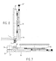
- Figures 7 and 8 show further possible adjusted positions of the image recording element.
- the device which is shown in the figures comprises a tabletop 1 which transmits X-rays, which tabletop is supported by two beams 2, 3 extending in the longitudinal direction of the tabletop, which are disposed near the sides of the tabletop ( Figure 5), along which beams the tabletop 1 is movable in longitudinal direction, that is, parallel to its longitudinal axis, to the left and to the right in Figure 4, as is indicated by means of dotted lines drawn in line with tabletop 1 in Figure 4.
- cross beams 5, 6, which are disposed near the ends of the tabletop, seen in Figure 4, which cross beams are movable in a direction transversely to the longitudinal direction of the tabletop with respect to a frame member 7 supporting the tabletop, as is indicated with position 2' of beam 2 and position 3' of beam 3 in Figure 5.
- Frame member 7 is connected to one end of a support 9 by means of a pivot pin 8 which extends horizontally and transversely to the longitudinal direction of tabletop 1.
- pivots 10 and 11 Connected to support 9, by means of pivots 10 and 11 disposed near pivot pin 8 and extending parallel thereto, are the ends of two arms 12 and 13, with arm 13 only being indicated by means of a chain-dotted line.
- the ends of the arms 12 and 13 remote from pivots 10 and 11 are connected to a connecting piece 16 by means of pivots 14 and 15, respectively, extending parallel to pivots 10 and 11, all this in such a manner that arms 12 and 13 and the associated pivots 10, 11 and 14, 15 form a parallelogram construction.
- connecting piece 16 Furthermore connected to connecting piece 16 are the ends of two arms 17 and 18, with arm 17 being pivotally connected to connecting piece 16 by means of pivot 14 and arm 18 being connected to connecting piece 16 by means of a pivot 19 which extends parallel to pivot 14. Like arm 13, arm 17 is indicated by means of chain-dotted lines.
- arms 17 and 18 extend downwards from connecting piece 16 in a direction away from arms 12 and 13, which extend upwards from connecting piece 16.
- arms 17 and 18, seen in Figure 1 are pivotally connected, by means of two parallel pivots 21 and 22, to a frame 20 of the device, which is disposed on the floor, all this in such a manner that also the arms 17 and 18 and the associated pivots 14, 19, 21 and 22 form a parallelogram construction.
- the arms 18 and 12 are interconnected by means of a gears 26 and 27, respectively, which are mounted on pivots 14 and 19.
- an adjusting element 26 for example a setting cylinder or the like, is mounted between the frame member 7 supporting tabletop 1 and support 9.
- frame member 7 can be pivoted from the position which is shown in Figure 1, in which the tabletop 1 occupies a vertical position and is locked in position for use of the device, through an angle of ⁇ 90° about pivot 8, as is indicated by arrow A, by means of said adjusting element 26 in order to move the tabletop 1 to a horizontal position.
- the tabletop that has been moved to a horizontal position can be moved upwards and downwards by means of setting cylinder 24, by pivoting of the above-described, interconnected parallelogram mechanisms, with a lowermost position of tabletop 1 being illustrated in Figure 4.
- a person to be examined can easily position himself on the tabletop, whilst the tabletop can be moved upwards in its horizontal position in order to bring the person within easier reach of the operating staff.
- the tabletop can also be disposed in a slightly inclined position by pivoting about pivot 8, as is indicated by means of dotted line 1' in Figure 4.
- the above-described mechanism for moving the tabletop upwards and downwards can be screened by a number of tubular members 28, which can telescope with respect to each other.
- Frame member 7 comprises a frame beam 7' extending in the longitudinal direction of the tabletop, along which a sliding member or trolley 29 ( Figure 5) is movable, for example by means of a chain drive.
- a sliding member or trolley 29 Figure 5
- Connected to sliding member 29 is a support or I-beam 30 extending under the tabletop, transversely to the longitudinal direction thereof.
- a sliding member 31 is movable along said support 30.
- a connecting piece 32 is pivotally connected to sliding member 30 by means of a pivot 31' extending vertically (seen in Figures 5 and 6) and thus perpendicularly to the tabletop 1.
- An arm 34 is pivotally connected to said connecting piece by means of a pivot 33 extending parallel to tabletop 1.
- a supporting member 35 is movable in the longitudinal direction of arm 34 with respect to said arm 34 by means of a grip 35' and capable of being locked in several desired positions with respect to arm 34.
- Supporting member 35 supports an image recording element 36 by means of wheels 37, all this in such a manner that the image recording element 36 is pivotable with respect to supporting member 35 and capable of being adjusted about a pivot 38 that crosses pivot 33 perpendicularly.
- image recording element 36 is a flat, box-like member, which houses sensors capable of detecting X-rays, which sensors transmit signals to the viewing screen or the like.
- the actual recording surface 39 of image recording element 38 which is illustrated in dotted lines, for example in Figure 2, is rectangular in shape and it is smaller than the outer circumference of the image recording element 36.
- the image recording element can be disposed in several positions 36', 36'' under the tabletop for forming X-ray images of a person who is lying on the tabletop.
- the image recording element can also pulled out from its position under the table and be disposed in a vertical position, as is shown in Figure 6.
- the recording surface 39 can be moved to a position in which the lower boundary line of said recording surface 39 is positioned at the same level as the upper side of tabletop 1, as is shown in Figure 6, or in a higher position, in which the entire recording element 36 is disposed above the tabletop, as is indicated in Figure 8.
- the recording element 36 in a horizontal position outside the tabletop, as is shown in Figure 7. In this position of the image recording element it is possible to place parts of the body, for example a person's hands, on the image recording element 36 for making X-ray images.
- the image recording element 36 can be moved in vertical direction with respect to tabletop 1 in the vertical position of tabletop 1, whereby the image recording element 36 may be disposed behind or beside the tabletop, as will be apparent from Figures 1 - 3, and the possibilities of pivoting the image recording element 36 about pivots 31' and 33 and the possibility to move the image recording element along support 30 in a direction transversely the longitudinal direction of tabletop 1 and in the longitudinal direction of arm 34 make it possible to position the image recording element 36 optimally with respect to the person to be examined.
- a further contribution to obtaining an optimum adjustment of the image recording element is obtained by the fact that the image recording element 36 is pivotable with respect to the supporting element 36 that is connected to the arm 34, about a pivot 38 extending perpendicularly to the recording surface 39 of the image recording element, so that also the recording surface 39, which is of rectangular section, can be adjusted to an optimum position. Also the possibility to move the tabletop 1 in two directions extending perpendicularly to each other contributes towards obtaining an optimum adjustment of the image recording element 36 with respect to the person to be examined.
- the device according to the invention makes it possible, using an image recording element 35, to obtain an X-ray image of each part of the body of a person to be examined with an optimum position of the person to be examined and the image recording element with respect to each other.
Landscapes
- Health & Medical Sciences (AREA)
- Life Sciences & Earth Sciences (AREA)
- Medical Informatics (AREA)
- Engineering & Computer Science (AREA)
- Physics & Mathematics (AREA)
- Pathology (AREA)
- Public Health (AREA)
- Biophysics (AREA)
- Nuclear Medicine, Radiotherapy & Molecular Imaging (AREA)
- Optics & Photonics (AREA)
- Veterinary Medicine (AREA)
- Radiology & Medical Imaging (AREA)
- Biomedical Technology (AREA)
- Heart & Thoracic Surgery (AREA)
- Molecular Biology (AREA)
- Surgery (AREA)
- Animal Behavior & Ethology (AREA)
- General Health & Medical Sciences (AREA)
- High Energy & Nuclear Physics (AREA)
- Mathematical Physics (AREA)
- Apparatus For Radiation Diagnosis (AREA)
- Memory System Of A Hierarchy Structure (AREA)
- Analysing Materials By The Use Of Radiation (AREA)
Abstract
Description
- The invention relates to a table for X-ray examination, comprising a tabletop supported by a frame, on which a person to be examined can lie in a horizontal position of the tabletop, whilst an image recording element, which is movable in a direction substantially parallel to the longitudinal direction of the tabletop, is connected to the tabletop, wherein the tabletop is vertically adjustable with respect to the frame and pivotable through an angle of ± 90° about a pivot pin extending transversely to the longitudinal axis of the tabletop.
- X-ray examination tables that have been usual so far are generally used in combination with an image recording element in the form of a cassette containing a photosensitive plate, by means of which an X-ray photo is made of at least a part of a person who is being irradiated by means of an X-ray source. Such an X-ray source is usually suspended from the ceiling or the like, and it can be moved both in vertical and in horizontal direction with respect to the table.
- In addition to that, devices are known which comprise a frame, along which an image recording element containing a photosensitive plate can be moved in vertical direction in order to make X-ray photos of a person in standing position. Such X-ray photos need to be developed, so that generally it takes some time before the results of the examination are known.
- Recently, recording elements in the form of detectors have been developed, which are capable of transmitting the X-ray images directly to a viewing screen, so that the result of the X-ray examination is directly visible.
- Such image recording elements are costly, however, so that an optimum use of such an element must be realised.
- From US-A-4,602,378 there is known a table of the above kind, wherein the image recording element can only be adjusted to a position in which it extends parallel to the tabletop.
- According to the invention, the image recording element is adjustable between a position in which the image recording element extends approximately perpendicularly to an imaginary plane comprising the upper side of the tabletop, and a position in which the image recording element extends substantially parallel to said imaginary plane.
- By using the construction according to the invention, a device of simple design having a wide range of applications is obtained. By means of a single image recording element it is possible not only to obtain X-ray images both of a person in standing position and of a person in reclined position, but also, in the horizontal position of the image recording element, to produce X-ray images of parts of the body being placed on the image recording element, such as a hand, for example.
- A further extension of the range of applications of the table is obtained in that the image recording element is movable from one side of the tabletop to the other, in a direction transversely to the longitudinal axis of the tabletop.
- The invention will now be explained in more detail by means of an embodiment of a table according to the invention as shown in the accompanying figures.
- Figure 1 is a view, partially in side elevation and partially in section, of a table according to the invention, wherein the tabletop is shown in a vertical position thereof.
- Figure 2 is a side view of Figure 1.
- Figure 3 is a side elevation substantially corresponding to Figure 2, wherein the image recording element is represented in various adjusted positions thereof.
- Figure 4 is a view, partially in section and partially in front elevation, of the table according to the invention, wherein the tabletop is shown in a horizontal position thereof.
- Figures 5 and 6 are larger-scale cross-sectional views of Figure 4, wherein the image recording element is shown in various positions thereof.
- Figures 7 and 8 show further possible adjusted positions of the image recording element.
- The device which is shown in the figures comprises a
tabletop 1 which transmits X-rays, which tabletop is supported by twobeams tabletop 1 is movable in longitudinal direction, that is, parallel to its longitudinal axis, to the left and to the right in Figure 4, as is indicated by means of dotted lines drawn in line withtabletop 1 in Figure 4. - The ends of the
frame beams cross beams frame member 7 supporting the tabletop, as is indicated with position 2' ofbeam 2 and position 3' ofbeam 3 in Figure 5. -
Frame member 7 is connected to one end of asupport 9 by means of apivot pin 8 which extends horizontally and transversely to the longitudinal direction oftabletop 1. - Connected to support 9, by means of
pivots pivot pin 8 and extending parallel thereto, are the ends of twoarms arm 13 only being indicated by means of a chain-dotted line. The ends of thearms pivots piece 16 by means ofpivots pivots arms pivots - Furthermore connected to connecting
piece 16 are the ends of twoarms 17 and 18, with arm 17 being pivotally connected to connectingpiece 16 by means ofpivot 14 andarm 18 being connected to connectingpiece 16 by means of apivot 19 which extends parallel topivot 14. Likearm 13, arm 17 is indicated by means of chain-dotted lines. - In Figure 1,
arms 17 and 18 extend downwards from connectingpiece 16 in a direction away fromarms piece 16. - The lower ends of
arms 17 and 18, seen in Figure 1, are pivotally connected, by means of twoparallel pivots frame 20 of the device, which is disposed on the floor, all this in such a manner that also thearms 17 and 18 and the associatedpivots - Connected to
arm 18, by means of apivot 23 extending parallel topivots cylinder 24. The other end of settingcylinder 24 is connected toframe 20 by means of apivot 25 extending parallel topivot 23. - As is furthermore shown in Figure 1, the
arms gears pivots - As is furthermore illustrated in a chain-dotted
line 26 in Figure 1, an adjustingelement 26, for example a setting cylinder or the like, is mounted between theframe member 7 supportingtabletop 1 and support 9. After being unlocked,frame member 7 can be pivoted from the position which is shown in Figure 1, in which thetabletop 1 occupies a vertical position and is locked in position for use of the device, through an angle of ± 90° aboutpivot 8, as is indicated by arrow A, by means of said adjustingelement 26 in order to move thetabletop 1 to a horizontal position. The tabletop that has been moved to a horizontal position can be moved upwards and downwards by means of settingcylinder 24, by pivoting of the above-described, interconnected parallelogram mechanisms, with a lowermost position oftabletop 1 being illustrated in Figure 4. In this position a person to be examined can easily position himself on the tabletop, whilst the tabletop can be moved upwards in its horizontal position in order to bring the person within easier reach of the operating staff. The tabletop can also be disposed in a slightly inclined position by pivoting aboutpivot 8, as is indicated by means of dotted line 1' in Figure 4. - As will furthermore be apparent from Figures 1 and 4, the above-described mechanism for moving the tabletop upwards and downwards can be screened by a number of
tubular members 28, which can telescope with respect to each other. -
Frame member 7 comprises a frame beam 7' extending in the longitudinal direction of the tabletop, along which a sliding member or trolley 29 (Figure 5) is movable, for example by means of a chain drive. Connected to slidingmember 29 is a support or I-beam 30 extending under the tabletop, transversely to the longitudinal direction thereof. A slidingmember 31 is movable along saidsupport 30. A connectingpiece 32 is pivotally connected to slidingmember 30 by means of a pivot 31' extending vertically (seen in Figures 5 and 6) and thus perpendicularly to thetabletop 1. Anarm 34 is pivotally connected to said connecting piece by means of apivot 33 extending parallel totabletop 1. A supportingmember 35 is movable in the longitudinal direction ofarm 34 with respect to saidarm 34 by means of a grip 35' and capable of being locked in several desired positions with respect toarm 34. - Supporting
member 35 supports an image recordingelement 36 by means ofwheels 37, all this in such a manner that the image recordingelement 36 is pivotable with respect to supportingmember 35 and capable of being adjusted about apivot 38 that crossespivot 33 perpendicularly. - In the illustrated embodiment,
image recording element 36 is a flat, box-like member, which houses sensors capable of detecting X-rays, which sensors transmit signals to the viewing screen or the like. - The
actual recording surface 39 ofimage recording element 38, which is illustrated in dotted lines, for example in Figure 2, is rectangular in shape and it is smaller than the outer circumference of theimage recording element 36. - As is shown in Figures 4 and 5, the image recording element can be disposed in several positions 36', 36'' under the tabletop for forming X-ray images of a person who is lying on the tabletop. In addition to that, the image recording element can also pulled out from its position under the table and be disposed in a vertical position, as is shown in Figure 6. By moving the
image recording element 36 in vertical direction, therecording surface 39 can be moved to a position in which the lower boundary line of saidrecording surface 39 is positioned at the same level as the upper side oftabletop 1, as is shown in Figure 6, or in a higher position, in which theentire recording element 36 is disposed above the tabletop, as is indicated in Figure 8. - Furthermore it is possible to dispose the
recording element 36 in a horizontal position outside the tabletop, as is shown in Figure 7. In this position of the image recording element it is possible to place parts of the body, for example a person's hands, on the image recordingelement 36 for making X-ray images. - As is apparent from Figures 1 - 3, in which several positions of one and the same image recording
element 36 are shown either in dotted lines or in full lines, theimage recording element 36 can be moved in vertical direction with respect totabletop 1 in the vertical position oftabletop 1, whereby theimage recording element 36 may be disposed behind or beside the tabletop, as will be apparent from Figures 1 - 3, and the possibilities of pivoting the image recordingelement 36 aboutpivots 31' and 33 and the possibility to move the image recording element alongsupport 30 in a direction transversely the longitudinal direction oftabletop 1 and in the longitudinal direction ofarm 34 make it possible to position theimage recording element 36 optimally with respect to the person to be examined. A further contribution to obtaining an optimum adjustment of the image recording element is obtained by the fact that theimage recording element 36 is pivotable with respect to the supportingelement 36 that is connected to thearm 34, about apivot 38 extending perpendicularly to therecording surface 39 of the image recording element, so that also therecording surface 39, which is of rectangular section, can be adjusted to an optimum position. Also the possibility to move thetabletop 1 in two directions extending perpendicularly to each other contributes towards obtaining an optimum adjustment of the image recordingelement 36 with respect to the person to be examined. - From the foregoing it will be apparent that the device according to the invention makes it possible, using an
image recording element 35, to obtain an X-ray image of each part of the body of a person to be examined with an optimum position of the person to be examined and the image recording element with respect to each other.
Claims (10)
- A table for X-ray examination, comprising a tabletop supported by a frame, on which a person to be examined can lie in a horizontal position of the tabletop, whilst an image recording element, which is movable in a direction substantially parallel to the longitudinal direction of the tabletop, is connected to the tabletop, wherein the tabletop is vertically adjustable with respect to the frame and pivotable through an angle of ± 90° about a pivot pin extending transversely to the longitudinal axis of the tabletop, characterized in that the image recording element is adjustable between a position in which the image recording element extends approximately perpendicularly to an imaginary plane comprising the upper side of the tabletop, and a position in which the image recording element extends substantially parallel to said imaginary plane comprising the upper side of the tabletop.
- A table according to claim 1, characterized in that the image recording element is movable from one side of the tabletop to the other, in a direction transversely to the longitudinal axis of the tabletop.
- A table according to claim 2, characterized in that the image recording element can be moved under the tabletop.
- A table according to any one of the preceding claims, characterized in that the image recording element is connected to a slide, which is movable along a support that extends under the tabletop, transversely to the longitudinal axis thereof, which support is movable in the longitudinal direction of the tabletop.
- A table according to claim 4, characterized in that the image recording element is pivotable with respect to said slide about a pivot which extends at least substantially perpendicularly the tabletop.
- A table according to claim 4 or 5, characterized in that the image recording element is pivotable with respect to said slide about a pivot extending parallel to the tabletop.
- A table according to claim 6, characterized in that the image recording element is supported by an arm which is pivotable about the pivot that extends parallel to the tabletop, along which arm the image recording element is movable and adjustable in several positions.
- A table according to claim 7, characterized in that the image recording element is pivotable with respect to the arm about a pivot extending perpendicularly to the recording surface of the image recording element.
- A table according to any one of the preceding claims, characterized in that the tabletop is adjustable in its longitudinal direction with respect to the frame.
- A table according to any one of the preceding claims, characterized in that the tabletop is adjustable in a direction transversely to its longitudinal direction.
Applications Claiming Priority (2)
| Application Number | Priority Date | Filing Date | Title |
|---|---|---|---|
| NL1014555 | 2000-03-03 | ||
| NL1014555A NL1014555C2 (en) | 2000-03-03 | 2000-03-03 | Table for X-ray examination. |
Publications (2)
| Publication Number | Publication Date |
|---|---|
| EP1129664A1 true EP1129664A1 (en) | 2001-09-05 |
| EP1129664B1 EP1129664B1 (en) | 2006-07-26 |
Family
ID=19770938
Family Applications (1)
| Application Number | Title | Priority Date | Filing Date |
|---|---|---|---|
| EP01200760A Expired - Lifetime EP1129664B1 (en) | 2000-03-03 | 2001-03-01 | Table for X-ray examination |
Country Status (6)
| Country | Link |
|---|---|
| US (1) | US20010027575A1 (en) |
| EP (1) | EP1129664B1 (en) |
| AT (1) | ATE333834T1 (en) |
| CA (1) | CA2336444A1 (en) |
| DE (1) | DE60121647D1 (en) |
| NL (1) | NL1014555C2 (en) |
Cited By (2)
| Publication number | Priority date | Publication date | Assignee | Title |
|---|---|---|---|---|
| WO2003024333A1 (en) * | 2001-09-19 | 2003-03-27 | Ao:S Metall & Mek. Verkstad Ab | A patient support table stand having a pivotable receptor unit |
| DE10352010B3 (en) * | 2003-11-07 | 2005-09-08 | Siemens Ag | Patient positioning device with positioning device |
Families Citing this family (2)
| Publication number | Priority date | Publication date | Assignee | Title |
|---|---|---|---|---|
| US6785578B2 (en) * | 2001-10-09 | 2004-08-31 | General Electric Company | User input device for controlling medical imaging equipment motion |
| US10980692B2 (en) * | 2016-08-29 | 2021-04-20 | Mobius Imaging, Llc | Table system for medical imaging |
Citations (3)
| Publication number | Priority date | Publication date | Assignee | Title |
|---|---|---|---|---|
| US4602378A (en) | 1982-08-19 | 1986-07-22 | General Electric Company | X-ray table |
| WO1996037088A1 (en) * | 1995-05-18 | 1996-11-21 | Continental X-Ray Corporation | Universal radiographic/fluoroscopic digital room |
| US6027247A (en) * | 1995-04-04 | 2000-02-22 | Hitachi Medical Corporation | X-ray photographing apparatus |
Family Cites Families (1)
| Publication number | Priority date | Publication date | Assignee | Title |
|---|---|---|---|---|
| US5764724A (en) * | 1994-07-28 | 1998-06-09 | Ao Medical Products Ab | Method of making X-ray photographs or exposures or other type of radiation sensoring, such as electronic image storage, and a patient table having a receptor unit for such photography, exposure or image storage |
-
2000
- 2000-03-03 NL NL1014555A patent/NL1014555C2/en not_active IP Right Cessation
-
2001
- 2001-03-01 AT AT01200760T patent/ATE333834T1/en not_active IP Right Cessation
- 2001-03-01 CA CA002336444A patent/CA2336444A1/en not_active Abandoned
- 2001-03-01 EP EP01200760A patent/EP1129664B1/en not_active Expired - Lifetime
- 2001-03-01 DE DE60121647T patent/DE60121647D1/en not_active Expired - Lifetime
- 2001-03-05 US US09/797,882 patent/US20010027575A1/en not_active Abandoned
Patent Citations (3)
| Publication number | Priority date | Publication date | Assignee | Title |
|---|---|---|---|---|
| US4602378A (en) | 1982-08-19 | 1986-07-22 | General Electric Company | X-ray table |
| US6027247A (en) * | 1995-04-04 | 2000-02-22 | Hitachi Medical Corporation | X-ray photographing apparatus |
| WO1996037088A1 (en) * | 1995-05-18 | 1996-11-21 | Continental X-Ray Corporation | Universal radiographic/fluoroscopic digital room |
Cited By (2)
| Publication number | Priority date | Publication date | Assignee | Title |
|---|---|---|---|---|
| WO2003024333A1 (en) * | 2001-09-19 | 2003-03-27 | Ao:S Metall & Mek. Verkstad Ab | A patient support table stand having a pivotable receptor unit |
| DE10352010B3 (en) * | 2003-11-07 | 2005-09-08 | Siemens Ag | Patient positioning device with positioning device |
Also Published As
| Publication number | Publication date |
|---|---|
| EP1129664B1 (en) | 2006-07-26 |
| US20010027575A1 (en) | 2001-10-11 |
| NL1014555C2 (en) | 2001-09-04 |
| DE60121647D1 (en) | 2006-09-07 |
| CA2336444A1 (en) | 2001-09-03 |
| ATE333834T1 (en) | 2006-08-15 |
Similar Documents
| Publication | Publication Date | Title |
|---|---|---|
| US7954996B2 (en) | Positioning system with tilting arm support for imaging devices | |
| US11266482B2 (en) | Balance mechanism and mobile medical device having the same | |
| JP2825721B2 (en) | Medical optical equipment stand device | |
| US4501011A (en) | Angulating lateral fluoroscopic suspension | |
| CA1282501C (en) | Mobile radiography alignment device | |
| CN104053985A (en) | Digital radiography mechanical positioning system | |
| JP2016501097A (en) | Ultrasonic system control panel and display lift | |
| JP4145517B2 (en) | X-ray system | |
| EP1129664A1 (en) | Table for X-ray examination | |
| CN1977768A (en) | X-ray apparatus | |
| JP2003310594A (en) | X-ray diagnostic device for mammography examination | |
| CN112714629B (en) | Mini C-arm with increased range of motion | |
| US3500045A (en) | Tiltable x-ray table supporting an x-ray tube and detector for displacement and rotation in two directions relative to the table | |
| US20110170660A1 (en) | X-ray detector | |
| GB2095080A (en) | Tilting table x-ray apparatus | |
| JP3597235B2 (en) | X-ray inspection equipment | |
| JPH10108860A (en) | X-ray equipment | |
| CN113924043A (en) | CT imaging equipment | |
| JPH1170108A5 (en) | ||
| US7125164B2 (en) | Digital radiography apparatus | |
| JPS59151945A (en) | X-ray table apparatus for tomography having false fulcrum point arm pivot shaft | |
| JPH067332A (en) | X-ray inspection device | |
| FR2821263A1 (en) | Remote-controlled patient support device for use in medical radiography or radiotherapy is highly flexible and allows x-ray tube and image receiver to be positioned such that all type of examination can be executed | |
| DK142395B (en) | X-ray apparatus with moving patient bed and movable radiation source and image amplifier. | |
| JP2816730B2 (en) | Radiology equipment with conformable points that can move in space |
Legal Events
| Date | Code | Title | Description |
|---|---|---|---|
| PUAI | Public reference made under article 153(3) epc to a published international application that has entered the european phase |
Free format text: ORIGINAL CODE: 0009012 |
|
| AK | Designated contracting states |
Kind code of ref document: A1 Designated state(s): AT BE CH CY DE DK ES FI FR GB GR IE IT LI LU MC NL PT SE TR |
|
| AX | Request for extension of the european patent |
Free format text: AL;LT;LV;MK;RO;SI |
|
| 17P | Request for examination filed |
Effective date: 20020208 |
|
| AKX | Designation fees paid |
Free format text: AT BE CH CY DE DK ES FI FR GB GR IE IT LI LU MC NL PT SE TR |
|
| 17Q | First examination report despatched |
Effective date: 20050518 |
|
| GRAP | Despatch of communication of intention to grant a patent |
Free format text: ORIGINAL CODE: EPIDOSNIGR1 |
|
| GRAS | Grant fee paid |
Free format text: ORIGINAL CODE: EPIDOSNIGR3 |
|
| GRAA | (expected) grant |
Free format text: ORIGINAL CODE: 0009210 |
|
| AK | Designated contracting states |
Kind code of ref document: B1 Designated state(s): AT BE CH CY DE DK ES FI FR GB GR IE IT LI LU MC NL PT SE TR |
|
| PG25 | Lapsed in a contracting state [announced via postgrant information from national office to epo] |
Ref country code: IT Free format text: LAPSE BECAUSE OF FAILURE TO SUBMIT A TRANSLATION OF THE DESCRIPTION OR TO PAY THE FEE WITHIN THE PRESCRIBED TIME-LIMIT;WARNING: LAPSES OF ITALIAN PATENTS WITH EFFECTIVE DATE BEFORE 2007 MAY HAVE OCCURRED AT ANY TIME BEFORE 2007. THE CORRECT EFFECTIVE DATE MAY BE DIFFERENT FROM THE ONE RECORDED. Effective date: 20060726 Ref country code: AT Free format text: LAPSE BECAUSE OF FAILURE TO SUBMIT A TRANSLATION OF THE DESCRIPTION OR TO PAY THE FEE WITHIN THE PRESCRIBED TIME-LIMIT Effective date: 20060726 Ref country code: CH Free format text: LAPSE BECAUSE OF FAILURE TO SUBMIT A TRANSLATION OF THE DESCRIPTION OR TO PAY THE FEE WITHIN THE PRESCRIBED TIME-LIMIT Effective date: 20060726 Ref country code: NL Free format text: LAPSE BECAUSE OF FAILURE TO SUBMIT A TRANSLATION OF THE DESCRIPTION OR TO PAY THE FEE WITHIN THE PRESCRIBED TIME-LIMIT Effective date: 20060726 Ref country code: BE Free format text: LAPSE BECAUSE OF FAILURE TO SUBMIT A TRANSLATION OF THE DESCRIPTION OR TO PAY THE FEE WITHIN THE PRESCRIBED TIME-LIMIT Effective date: 20060726 Ref country code: LI Free format text: LAPSE BECAUSE OF FAILURE TO SUBMIT A TRANSLATION OF THE DESCRIPTION OR TO PAY THE FEE WITHIN THE PRESCRIBED TIME-LIMIT Effective date: 20060726 Ref country code: FI Free format text: LAPSE BECAUSE OF FAILURE TO SUBMIT A TRANSLATION OF THE DESCRIPTION OR TO PAY THE FEE WITHIN THE PRESCRIBED TIME-LIMIT Effective date: 20060726 |
|
| REG | Reference to a national code |
Ref country code: GB Ref legal event code: FG4D |
|
| REG | Reference to a national code |
Ref country code: CH Ref legal event code: EP |
|
| REG | Reference to a national code |
Ref country code: IE Ref legal event code: FG4D |
|
| REF | Corresponds to: |
Ref document number: 60121647 Country of ref document: DE Date of ref document: 20060907 Kind code of ref document: P |
|
| PG25 | Lapsed in a contracting state [announced via postgrant information from national office to epo] |
Ref country code: DK Free format text: LAPSE BECAUSE OF FAILURE TO SUBMIT A TRANSLATION OF THE DESCRIPTION OR TO PAY THE FEE WITHIN THE PRESCRIBED TIME-LIMIT Effective date: 20061026 Ref country code: SE Free format text: LAPSE BECAUSE OF FAILURE TO SUBMIT A TRANSLATION OF THE DESCRIPTION OR TO PAY THE FEE WITHIN THE PRESCRIBED TIME-LIMIT Effective date: 20061026 |
|
| PG25 | Lapsed in a contracting state [announced via postgrant information from national office to epo] |
Ref country code: DE Free format text: LAPSE BECAUSE OF FAILURE TO SUBMIT A TRANSLATION OF THE DESCRIPTION OR TO PAY THE FEE WITHIN THE PRESCRIBED TIME-LIMIT Effective date: 20061027 |
|
| PG25 | Lapsed in a contracting state [announced via postgrant information from national office to epo] |
Ref country code: ES Free format text: LAPSE BECAUSE OF FAILURE TO SUBMIT A TRANSLATION OF THE DESCRIPTION OR TO PAY THE FEE WITHIN THE PRESCRIBED TIME-LIMIT Effective date: 20061106 |
|
| PG25 | Lapsed in a contracting state [announced via postgrant information from national office to epo] |
Ref country code: PT Free format text: LAPSE BECAUSE OF FAILURE TO SUBMIT A TRANSLATION OF THE DESCRIPTION OR TO PAY THE FEE WITHIN THE PRESCRIBED TIME-LIMIT Effective date: 20061226 |
|
| NLV1 | Nl: lapsed or annulled due to failure to fulfill the requirements of art. 29p and 29m of the patents act | ||
| ET | Fr: translation filed | ||
| PLBE | No opposition filed within time limit |
Free format text: ORIGINAL CODE: 0009261 |
|
| STAA | Information on the status of an ep patent application or granted ep patent |
Free format text: STATUS: NO OPPOSITION FILED WITHIN TIME LIMIT |
|
| 26N | No opposition filed |
Effective date: 20070427 |
|
| PGFP | Annual fee paid to national office [announced via postgrant information from national office to epo] |
Ref country code: IE Payment date: 20070720 Year of fee payment: 7 |
|
| PG25 | Lapsed in a contracting state [announced via postgrant information from national office to epo] |
Ref country code: MC Free format text: LAPSE BECAUSE OF NON-PAYMENT OF DUE FEES Effective date: 20070331 |
|
| PG25 | Lapsed in a contracting state [announced via postgrant information from national office to epo] |
Ref country code: GR Free format text: LAPSE BECAUSE OF FAILURE TO SUBMIT A TRANSLATION OF THE DESCRIPTION OR TO PAY THE FEE WITHIN THE PRESCRIBED TIME-LIMIT Effective date: 20061027 |
|
| PGFP | Annual fee paid to national office [announced via postgrant information from national office to epo] |
Ref country code: GB Payment date: 20080117 Year of fee payment: 8 |
|
| PGFP | Annual fee paid to national office [announced via postgrant information from national office to epo] |
Ref country code: FR Payment date: 20080122 Year of fee payment: 8 |
|
| PG25 | Lapsed in a contracting state [announced via postgrant information from national office to epo] |
Ref country code: IE Free format text: LAPSE BECAUSE OF NON-PAYMENT OF DUE FEES Effective date: 20080303 |
|
| PG25 | Lapsed in a contracting state [announced via postgrant information from national office to epo] |
Ref country code: LU Free format text: LAPSE BECAUSE OF NON-PAYMENT OF DUE FEES Effective date: 20070301 Ref country code: CY Free format text: LAPSE BECAUSE OF FAILURE TO SUBMIT A TRANSLATION OF THE DESCRIPTION OR TO PAY THE FEE WITHIN THE PRESCRIBED TIME-LIMIT Effective date: 20060726 |
|
| PG25 | Lapsed in a contracting state [announced via postgrant information from national office to epo] |
Ref country code: TR Free format text: LAPSE BECAUSE OF FAILURE TO SUBMIT A TRANSLATION OF THE DESCRIPTION OR TO PAY THE FEE WITHIN THE PRESCRIBED TIME-LIMIT Effective date: 20060726 |
|
| GBPC | Gb: european patent ceased through non-payment of renewal fee |
Effective date: 20090301 |
|
| REG | Reference to a national code |
Ref country code: FR Ref legal event code: ST Effective date: 20091130 |
|
| PG25 | Lapsed in a contracting state [announced via postgrant information from national office to epo] |
Ref country code: FR Free format text: LAPSE BECAUSE OF NON-PAYMENT OF DUE FEES Effective date: 20091123 Ref country code: GB Free format text: LAPSE BECAUSE OF NON-PAYMENT OF DUE FEES Effective date: 20090301 |