EP1128609B1 - Packet classification engine - Google Patents
Packet classification engine Download PDFInfo
- Publication number
- EP1128609B1 EP1128609B1 EP00310753A EP00310753A EP1128609B1 EP 1128609 B1 EP1128609 B1 EP 1128609B1 EP 00310753 A EP00310753 A EP 00310753A EP 00310753 A EP00310753 A EP 00310753A EP 1128609 B1 EP1128609 B1 EP 1128609B1
- Authority
- EP
- European Patent Office
- Prior art keywords
- entry
- packet classification
- criterion
- memory
- rule
- Prior art date
- Legal status (The legal status is an assumption and is not a legal conclusion. Google has not performed a legal analysis and makes no representation as to the accuracy of the status listed.)
- Expired - Lifetime
Links
Images


Classifications
-
- H—ELECTRICITY
- H04—ELECTRIC COMMUNICATION TECHNIQUE
- H04L—TRANSMISSION OF DIGITAL INFORMATION, e.g. TELEGRAPHIC COMMUNICATION
- H04L47/00—Traffic control in data switching networks
- H04L47/10—Flow control; Congestion control
-
- H—ELECTRICITY
- H04—ELECTRIC COMMUNICATION TECHNIQUE
- H04L—TRANSMISSION OF DIGITAL INFORMATION, e.g. TELEGRAPHIC COMMUNICATION
- H04L47/00—Traffic control in data switching networks
- H04L47/10—Flow control; Congestion control
- H04L47/24—Traffic characterised by specific attributes, e.g. priority or QoS
- H04L47/2441—Traffic characterised by specific attributes, e.g. priority or QoS relying on flow classification, e.g. using integrated services [IntServ]
-
- H—ELECTRICITY
- H04—ELECTRIC COMMUNICATION TECHNIQUE
- H04L—TRANSMISSION OF DIGITAL INFORMATION, e.g. TELEGRAPHIC COMMUNICATION
- H04L47/00—Traffic control in data switching networks
- H04L47/10—Flow control; Congestion control
- H04L47/43—Assembling or disassembling of packets, e.g. segmentation and reassembly [SAR]
Definitions
- the present invention is related to the field of data communication networks.
- network devices such as switches are used to route packets through the network.
- Each switch typically has a number of line interfaces, each connected to a different network segment.
- forwarding logic determines which line interface the packet should be transmitted from, and the packet is transferred to the appropriate outgoing line interface to be sent toward its destination in the network.
- Packet filtering can be used to achieve various network management goals, such as traffic monitoring and security goals. Filtering criteria are established by network administrators, and provided to the switches or other devices that carry out the filtering operation. Packets received by the switches are examined to determine whether their characteristics match the criteria for any of the established filters. For packets that satisfy the criteria for one or more filters, predetermined actions associated with those filters are carried out. For example, under certain circumstances it may be desirable that packets originating from a given network node be discarded rather than being forwarded in the network.
- a filter can be defined in which the criterion is that a packet source address exactly match a specific value, which is the address of the node whose packets are to be discarded. The action associated with the filter is the discarding of the packet. When a packet is received whose source address satisfies this criterion, it is discarded rather than being forwarded in the normal fashion.
- criteria include exact matches as well as range checking, i.e., checking whether a value in a packet falls in some range of values.
- Numerous packet parameters can be used as criteria, such as source address, destination address, port identifiers, type of service, and others. To be useful, packet filtering processes must allow filters to be flexibly defined using different combinations of these and other criteria.
- Bannatyne R et al "Introduction to microcontrollers" WESCON/97. Conference Proceedings Santa Clara, CA, USA 4-6 Nov. 1997, New York, NY, USA, IEEE, US, 4 November 1997 (1997-11-04), pages 564-574, provides a basic introduction to the components and functions of a microcontroller.
- WO-A-99 00 935 discloses a multi-layered network element for forwarding received packets from an input port to one or more output ports.
- Apparatus according to the invention is as set out in claim 1. Preferred forms are set out in the dependent claims.
- packet processing logic in a network device that provides high-speed packet classification for packet filtering purposes.
- the architecture of the classification apparatus provides substantial flexibility in the definition of complex filter criteria- Robust filtering can be performed at a sufficiently high rate to avoid degrading packet forwarding performance.
- the packet classification apparatus includes a rule memory and a criterion memory.
- One type of rule memory entry contains an operator and a pointer to a criterion memory entry.
- the operator defines a comparison operation to be performed, such as EQUAL (exact match) or LESS THAN.
- the criterion memory entry contains one or more values to be used as comparands on one side of the comparison, where corresponding values from a received packet appear on the other side of the comparison.
- one comparand from criterion memory may represent a source address. This value is compared with the value appearing in the source address field of received packets.
- Control logic responds to packet classification requests to retrieve a rule memory entry from the rule memory, retrieve the criterion memory entry identified by the criterion memory pointer in the rule memory entry, and perform the operation specified by the operator in the rule memory entry on the values in the criterion memory entry and corresponding values included in the classification request. This procedure is repeated for a sequence of rule memory entries until a certain ending condition is encountered, whereupon a packet classification result is generated reflecting the result of the classification operations. This result is provided to a packet processor to take theappropriate action based on the classification result.
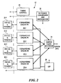
- a network switch 10 is shown as including a number of line interfaces 12 connected to respective network segments 14.
- the line interfaces 12 are connected to a switch fabric 16 used to provide connections among the line interfaces 12 for packet forwarding.
- the overall operation of the switch 10, including the dynamic configuration of the switch fabric 16, is controlled by a switch control 18.
- the various network segments 14 may be of different types.
- certain of the network segments 14 may be optical links operating at any of a variety of standard signalling rates, such as OC-3/STM-1 and OC-12/STM-4.
- Others of the network segments 14 may be non-optical links employing coaxial cable, for example, and carrying signals of different formats.
- Each line interface 12 is of course designed for operation with the specific type of network segment 14 to which it connects.
- the primary tasks of each line interface 12 are to transfer packets or frames received from an attached network segment 14 to another line interface 12 via the switch fabric 16 for forwarding on a network segment 14 attached to the other line interface 12, and to receive packets from the other line interfaces 12 via the switch fabric 16 for forwarding on the attached network segment 14.
- FIG. 2 shows the structure of one type of line interface 12.
- This interface contains four separate optical interface ports, each including physical input/output and framing circuitry 20 and a forwarding engine 22.
- the forwarding engines 22 are all connected to switch fabric interface logic 24, which interfaces with the switch fabric 16 of Figure 1.
- the forwarding engines also interface with a line interface I/O processor (IOP) 26.
- IOP line interface I/O processor
- Timing control logic 28 and DC power circuitry 30 are also included.
- Each forwarding engine 22 provides a bidirectional data path between a connected physical I/O block 20 and the switch fabric interface 24.
- Received packets are segmented into multiple fixed-size ATM-like cells for transfer through the switch fabric 16 of Figure I to another line interface 12.
- Cells received from the switch fabric 16 via the switch fabric interface 24 are reassembled into packets for outgoing transfer to the connected physical I/O block 20.
- the IOP 26 is a general-purpose processor that performs background functions, i.e. functions that support the forwarding of packets that are not carried out on a per-packet basis.
- One function performed by the IOP 26 is receiving packet forwarding information and packet filtering information from the switch control 18 of Figure 1, and distributing the information to the forwarding engines 22. This process is described below.
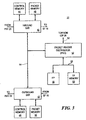
- FIG. 3 shows a block diagram of a forwarding engine 22.
- An inbound segmentation-and-reassembly (SAR) logic block 40 provides a data path from a physical I/O block 20 to the switch fabric 16 of Figure 2, and an outbound SAR logic block 42 provides a data path from the switch fabric 16 to the respective physical I/O block 20.
- SAR 40, 42 is coupled to a respective control memory 44, 46 and packet memory 48, 50 used in performing the segmentation or reassembly function.
- the SAR devices 40 and 42 are both connected to a packet header distributor (PHD) application-specific integrated circuit (ASIC) 52 via a 64-bit PCI bus 54.
- PHD packet header distributor
- ASIC application-specific integrated circuit
- the PHD ASIC 52 provides FIFO queue interfaces between the PCI bus 54 and a separate 64-bit bus 56.
- the bus 56 connects the PHD ASIC 52 with a forwarding processor (FP) 58 and forwarding processor memory 60.
- FP forwarding processor
- the PHD ASIC 52 is also connected to the IOP 26 of Figure 2 by a separate bus 62.
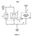
- FIG. 4 shows the structure of the PHD 52 of Figure 3.
- a set of receive queues or RX queues 64 is used for temporary buffering of packet headers and other messages bound for the FP 58.
- there are four RX queues 64 two queues for high-priority traffic and two queues for low-priority traffic.
- An example of high-priority traffic is traffic having a high Quality of Service (QOS) guarantee, such as a committed rate.
- QOS Quality of Service
- Low-priority traffic is traffic having a lower QOS or no QOS guarantee, such as best-efforts.
- QOS Quality of Service
- a set of transmit queues or TX queues 66 is used for temporary buffering of packet headers and other messages bound for the SARs 40, 42 from the FP 58.
- a route and classification engine 68 performs a route lookup and various packet filtering checks on behalf of the FP 58. The packet filtering operation is described below.
- the route and classification engine 68 receives status information from the queues 64, 66 via signal lines 69, and makes this information available to the FP 58 in a manner described below.
- Packets are received by the inbound SAR 40 from the associated physical-layer circuitry 20 of Figure 2, and are stored in the packet memory 48.
- the inbound SAR 40 transfers the packet headers to an appropriate one of the RX queues 64 in the PHD 52.
- the FP 58 polls the PHD 52 to determine queue status, and retrieves the packet headers from the RX queues 64 as appropriate.
- the FP 58 sends certain information elements from each header to the route and classification engine 68 in a route and classification request.
- the route and classification engine 68 performs a route lookup and various packet filtering checks against the header elements in the request, and places the results of these checks into a result queue (described below).
- the FP 58 obtains the route lookup and classification results from the result queue, and uses these results to create a new header for the packet.
- the new header is transferred back to the PHD 52 via one of the TX queues 66, along with information identifying the internal circuit on which the packet should be forwarded after segmentation.
- the inbound SAR 40 retrieves the new header, places it in the packet memory 48 with the payload portion of the received packet, segments the new packet and transfers the resulting cells to the switch fabric 16 of Figure I on the internal circuit specified by the FP 58.
- the outbound SAR 42 receives packets from the switch fabric 16 of Figure 1, and reassembles these packets into the packet memory 50. Packet headers are sent to the PHD 52, and retrieved from the PHD 52 by the FP 58. For most packets, the route lookup and filtering checks will have already been performed during inbound processing, so these operations are not repeated. Some protocols, however, do require lookups and filtering for both inbound and outbound packets, and therefore these operations are optionally performed by the FP 58 in conjunction with the route and classification engine 68. If appropriate, the FP 58 formulates a new header for the packet, based in part on the identity of the internal circuit on which the segmented outbound packet is received.
- This new header is written to the PHD 52, along with transmit circuit information.
- the PHD 52 transfers the new header to the outbound SAR 42.
- the outbound SAR 42 places the new header in the packet memory 50 along with the packet payload, and transmits the packet to the associated physical layer interface 20 of Figure 2.
- FIG. 5 shows the structure of the route and classification engine 68.
- Requests from the FP 58 of Figure 3 are placed into a single request queue 70, and results are returned in a single result queue 72.
- Each queue 70 and 72 holds up to 16 request/result entries.
- a route lookup engine (RLE) 74 performs route lookups, typically based on a destination address (DA) included in the header.
- a packet classification engine (PCE) 76 performs packet filtering checks, based on specified information included in the packet header. The operation of the PCE 76 is described in more detail below.
- Input FIFO buffers 78 are placed between the request queue 70 and the RLE 74 and PCE 76, and output FIFO buffers 80 are placed between the RLE 74 and PCE 76 and the result queue 72.
- the FIFOs 78 and 80 provide a measure of decoupling between the processing performed by the RLE 74 and the processing performed by the PCE 76.
- a multiplexer 81 enables the FP 58 to read either the result queue 72, or status information including status from the request queue 70, the result queue 72, and the status appearing on the signal lines 69 of Figure 4. The structure of these entries is described below.
- Figure 6 shows the structure of the route and classification request that is passed to the PCE 76 and RLE 74 via the request queue 70 of Figure 5.
- the size of the request is four 64-bit words.
- IP TOS Type of Service
- TCP Flags The contents of the TCP Flags field of the received packet IP Source Address The IP Source Address of the received packet IP Dest. Addr.
- IP Destination Address of the received packet TCP/UDP Source Port The identifier of the TCP/UDP port on which the packet was received - TCP/UDP Dest. Port The identifier of the TCP/UDP port for which the received packet is destined Reserved Unused reserved bits
- the appropriate fields of the request are provided to the respective input FIFOs 78 for the RLE 74 and PCE 76 of Figure 5.
- Some of the fields, such as the Req. ID and the IP Dest. Addr., are provided to both the RLE 74 and the PCE 76.
- Other fields are provided to only one or the other. The use of the fields routed to the PCE in particular is described below.
- Figure 7 and Figure 8 show the respective structures of the two different types of entries that are read from the route and classification engine 68 of Figure 4.
- Figure 7 shows a result entry, which is obtained from the result queue 72 of Figure 5 and conveys the result of a classification search.
- Figure 8 shows a status entry used to convey status information to the FP 58 of Figure 3.
- the fields of the status entry shown in Figure 8 are defined as follows: FIELD NAME DESCRIPTION Zero Unused, set to zero TX Message Remaining space in forwarding-processor-to-IOP message queue RCE Results Number of pending entries in result queue 72. Normally zero, because status inserted only when queue is empty. RCE Requests Number of empty entries in request queue 70 Tx-0 ⁇ Number of empty entries Tx-1 ⁇ in TX queues 66. Hi-0 ⁇ Hi-1
- the FP 58 of Figure 3 writes lookup and classification requests to the request queue 70.
- different information elements from the request are written simultaneously into the respective input FIFOs 78 for the RLE 74 and the PCE 76.
- the RLE 74 and PCE 76 operate on the separate pieces of each request independently, and in general finish their respective processing operations for a given request at different times.
- the results of these operations are written to the output FIFOs 80.
- both sets of results for a given packet have reached the front of the output FIFOs 80, a single combined result is written to the result queue 72.
- the combined results are read by the FP 58 and used to formulate new packet headers and circuit information for the SARs 40 and 42 of Figure 3, as discussed above.
- the FP 68 uses the route and classification engine 68 in a batch fashion. When there is sufficient room in the request queue 70, a burst of requests are written. Respective portions of each request are handled by the PCE 76 and RLE 74, as previously mentioned.
- the FP obtains results by issuing a read command to the RCE 68. For each read, a block of four 64-bit entries are returned to the FP 58 via the FP bus 56. Each block contains as many results from the result queue 72 as are available at the time of the read, and a number of status entries as padding. Thus, one of five different combinations of entries in a result block may be read:
- the FP 58 will generally issue read commands until the result queue 72 is empty, which is inferred whenever one or more status entries are included in the result block. The FP 58 then uses these results while the route and classification engine 68 processes the next batch of requests. The FP 58 uses the status information to manage the flow of requests, so that the RLE 74 and PCE 76 are kept busy and the queues 70 and 72 and FIFOs 78 and 80 are prevented from overflowing.
- One significant advantage of appending status information to results is improved efficiency in using the FP bus 56. Whenever the FP 58 issues a read for results, either useful results or useful status information is returned. Additionally, the result block is returned in burst fashion, so that overhead associated with reading is reduced. Also, the FP 58 obtains information about the queues around the RLE 74 and PCE 76, and about the RX queues 64 and TX queues 66, in a single read transaction.
- Figure 9 shows the structure of the PCE 76 of Figure 5.
- Data representing filters and bindings are stored in a rule memory (RM) 82 and a criterion memory (CM) 84.
- the CM 84 includes three commonly addressed memories CM0 86, CM1 88 and CM2 90.
- Three comparison logic blocks 92, 94 and 96 are associated with respective ones of the criterion memories 86, 88 and 90.
- Addressing and control logic 98 decodes requests received from the request queue 70 of Figure 5, generates addresses for the RM 82 and the CM 84, sequences through multiple rules as required by each request, and generates results that are passed back to the result queue 72 of Figure 5.
- the addressing and control logic 98 also interfaces to the IOP 26 of Figure 2 to enable the reading and writing of the RM 82 and CM 84 by the IOP 26.
- Bus transceivers 100 provide the necessary data path between the IOP 26 and the RM 82 and CM 84.
- An AND gate 102 provides a single MATCH signal when corresponding MATCHn outputs from the comparison logic blocks 92, 94 and 96 are all true.
- Rule sets for packet filtering are typically originated by a Network Management Station (NMS), but can also be dynamically assigned by the FP 58 based on identified flows. Part or all of the following information is provided by the NMS or FP 58 for filters: IP Destination Address with mask; IP Source Address with mask; IP protocol identifier; TCP/UDP Source Port and Destination Port identifiers; IP Type of Service identifier and mask, and miscellaneous flags.
- the various information elements from a filter are compared with corresponding elements from each received packet in order to determine whether the packet matches the fitter criteria. If so, some specific action for the filter is taken, such as intentionally discarding a packet. If not, some default action is typically taken, such as allowing the packet to proceed toward its destination.
- packet filters are represented as an ordered list of comparison sets that are searched linearly.
- the filter elements are divided into criteria (the comparison values) and rules (the list itself and the operators to be used for each comparison). This separation of rules and criteria is reflected in the use of separate rule memory (RM) 82 and criterion memory (CM) 84.
- the memories 82 and 84 are separately optimized for their respective functions, thus enhancing efficiency and performance.
- entries within the CM 84 can be referred to by multiple rules in the RM 82, further enhancing storage efficiency.
- the RM 82 contains an array of rule memory entries, each of which may be one of two types.
- a first type contains a set of operators and a pointer to a row of CM 84 that stores comparands for a corresponding filter.
- a second type contains a pointer to another rule memory entry. These entries are used to perform jumps between non-contiguous segments in a set of rules being searched sequentially.
- the RM 82 can contain up to 16K entries.
- the CM 84 is segmented into three separate memories CM0 86, CM 1 88 and CM2 90, each of which can contain up to 4K entries in the illustrated embodiment.
- the organization of the CM 84 exploits a hierarchy that is inherent in IP packet classification. Because filtering on certain fields is usually accompanied by filtering based on other fields as well, it is reasonable to restrict which fields are stored in the separate memories CM0, CM1, and CM2. These restrictions further enhance storage efficiency.
- the most commonly filtered fields, Source Address and Destination Address are supported in all three memories CM0 86, CM1 88 and CM2 90. As described below, other fields are supported only in CMI 88 and/or CM2 90. This architecture maximizes the flexibility with which space in the CM 84 can be allocated, while at the same time enabling powerful parallel searches.
- the structure and use of CM 84 are described in more detail below.
- Figure 10 shows the structure of the entries in the RM 82 of Figure 9, which are also referred to as rule memory entries.
- Each 39-bit entry has a 1-bit Type field. If this field is 1, then bits 13-0 of the entry contain a pointer to another location in the RM 82, i.e., a pointer to another rule memory entry. If this field is 0, the entry contains information for performing a filter check. In this case, bits 11-0 contain an address of a row of CM 84 where operands for the check are to be found, and bits 35-12 contain encodings of operations to be performed on respective operands and fields from the request. These operations are described in more detail below.
- Bit 36 is a Carry bit used to form compound rules, for example to perform range checking.
- Bit 37 is a Done bit indicating that the last of a string of rules to be checked as part of a request has been reached.
- the criterion operator field contains eight 3-bit logical operator codes. Each operator code specifies an operation to be performed on corresponding comparands selected from the request and the criterion memory entry.
- the fields of the criterion memory entry are described below.
- the assignment of criterion operator bits to comparands is as follows: 35-33 CM0 SA/DA field 32-30 CM1 Protocol field 29-27 CM1 Source Port field 26-24 CM1 SA/DA or DP field 23-21 CM2 Protocol field 20-18 CM2 TOS or TOS with mask field 17-15 CM2 Source port or Flags with mask field 14-12 CM2 SA/DA or SP or DP field
- the operator code specifies a comparison to be performed, where the comparand from the request is on the left of the operator and the comparand from the criterion memory entry is on the right. For example, if the operator is ">", then the expression evaluated is (request data > criterion data).
- the operator codes are as follows: 000 Greater than 001 Lessthan 010 Equal 011 Not Equal 1xx Don't care (i.e. force TRUE regardless of comparand values)
- the criterion operators are used to configure logic within the comparison logic blocks 92, 94, and 96 in a manner described below.
- FIG 11 shows the structure of the entries in CM0 86 of Figure 9.
- Each entry is 38 bits wide.
- a single bit, bit 37, is used to distinguish between two possible configurations for the entry, as either a 32-bit source address (SA) or a 32-bit destination address (DA).
- Bits 31-0 contain an SA or DA value as required by a corresponding filter.
- Bits 36-32 contain a 5-bit encoded mask value that is used to limit the extent of the comparison between the SA/DA in the entry and the SA/DA of the request. The use of the mask is described in more detail below.
- Figure 12 shows the structure of the entries in CM1 88 of Figure 9. Each entry is 47 bits wide. Four different configurations are possible, as indicated by bits 46-45.
- the PTCL field identifies an IP protocol in all four configurations.
- the 16-bit SP and DP fields in configurations 2 and 3 represent source port and destination port identifiers, respectively.
- the contents of bits 36-32 are undefined in configurations 2 and 3.
- FIG 13 shows the structure of the entries in CM2 90 of Figure 9. Each entry is 51 bits wide. Eight different configurations are possible, as indicated by bits 50-48.
- the TOS field of configurations 2 through 7 identifies an IP Type of Service.
- the TOS Mask field contains an 8-bit mask used to limit the extent of the TOS comparison, as described below.
- the 8-bit FLAGS field contains flag values to be compared against corresponding flag bits from TCP/UDP packets.
- the 8-bit FLGS MSK field is used to limit the extent of the FLAGS comparison, as described below.
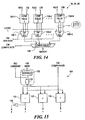
- Figure 14 shows the general structure of the comparison logic blocks 92, 94 and 96.
- Two or more blocks of comparator logic 104-1, ... 104-n are used to perform multiple comparisons in parallel, where each comparison is between a given field of a request and a corresponding field of a criterion memory entry.
- the comparison logic 92 for CMO 86 for example, two comparator logic blocks 104 are employed, one for the Source Address field of the request and one for the Destination Address field of the request.
- the comparison logic 94 for CMI 88 contains comparator logic blocks 104 for Source Address, Destination Address, IP Protocol, Source Port and Destination Port.
- the comparison logic 96 for CM2 90 contains comparator logic blocks 104 for Source Address, Destination Address, IP Protocol, Source Port, Destination Port, Type of Service without mask, Type of Service with mask, and Flags.
- the selectors 106 receive the operators from an operator-type rule memory entry as control inputs. These operators reside within bits 35-12 of the rule memory entry, as described above.
- the respective outputs of the selectors 106 are provided to another selector 108, which selects from among different combinations of the outputs of the selectors 106 based on the configuration bits from the criterion memory entry.
- the configuration selector 108 selects between a SA comparison result and a DA comparison result based on the value of bit 37 of the criterion memory entry.
- the configuration selectors 108 in the other comparison logic blocks 94 and 96 operate similarly.
- the output signal MATCH from the configuration selector 108 indicates whether the data in the request satisfies the criteria from the respective criterion memory 86, 88 or 90.
- the MATCH outputs from the comparison blocks 92, 94 and 96 are ANDed together by an AND gate 10, to provide a single MATCH indication to the addressing and control logic 98 for controlling the classification operation.
- Figure 15 shows the general structure of a comparator logic block 104.
- An EQUAL comparator 110 determines whether two comparands are equal, a LESS THAN comparator 112 determines whether one of the comparands is less than the other comparand, and a GREATER THAN comparator 114 determines whether the one comparand is greater than the other comparand.
- the output from the EQUAL comparator 110 is inverted by an inverter 116 to obtain the NOT EQUAL indication.
- each comparator 110, 112, and 114 are a comparand from the CM 84 (shown as "CM comparand") and a possibly masked comparand from the request (shown as REQ comparand).
- Masking logic is used for those fields having associated masks.
- AND gates 118 implement bit-by-bit masking.
- the multi-bit mask (shown as "CM mask”) may be used directly, as in the case of the Flags Mask, or it may be decoded or expanded by expander logic 120, as in the case of the SA/DA Mask.
- the expander logic 120 generates a 32-bit value having zeroes in a number of trailing bit positions as indicated by the 5-bit encoded mask value, and ones elsewhere.
- the decoded mask is FFFFF800 hexadecimal, which has ones in the leading 21 positions and zeros in the trailing 11 positions. This mask indicates that only the most significant 21 bits of the SA/DA should affect the comparison result.
- PCE packet classification engine
- the CM 84 can be used in a variety of different configurations.
- Each of the three memories CM0 86, CM1 88 and CM2 90 can be used in different modes to realize the different configurations.
- the following truth table presents the different comparisons that can be performed using the different configuration modes of the criteria memories 86, 88 and 90. A "1" indicates that a comparison can be performed using a given configuration mode, and a "0" indicates that the comparison cannot be performed.
- an SA comparison can be performed using any of CM0-0, CM1-0, and CM2-0.
- a FLAGS comparison can be performed using any of CM2-4 through CM2-7.
- the ability to perform a given comparison using any of a variety of configuration modes provides desirable flexibility in organizing CM 84, which in turn enhances efficiency.
- the allocation of criterion memory space is described in some detail below.
- Figure 16 shows the manner in which packet filtering information is managed and utilized in the switch 10 of Figure 1.
- the source of packet filtering information is a network management station (NMS), which is typically located apart from the switch 10 of Figure 1.
- the NMS communicates with a central processor (CP) residing within the switch control 18 of Figure 1 using a network management protocol such as Simple Network Management Protocol (SNMP).
- SNMP Simple Network Management Protocol
- the CP receives the filtering information from the NMS, and is responsible for distributing it to the IOP 26 of each line interface 12. Additionally, the CP maintains the information in non-volatile (NV) storage, so that the switch 10 is able to operate during periods when the NMS may be unavailable.
- NV non-volatile
- the filter information sent from the CP to the IOP 26 includes (1) filters, each of which specifies up to a small number of criteria that can be applied to received packets, (2) bindings, that is, information associating different groups of the filters with different ports and/or circuits in the switch 10, and (3) actions, having associations with the filters, which are to be performed when filter criteria are satisfied.
- the CP retrieves an existing filtering table and binding database from the NV storage and downloads them to the IOP 26 of each line interface 12.
- the NMS adds, deletes or modifies a filter or binding, it issues an SNMP action request to pass the new information to the CP.
- the CP posts the change to each IOP 26.
- the IOP 26 receives the filtering information from the CP and instantiates local copies of the filters, bindings and actions into its memory. The IOP 26 updates these local copies whenever the CP sends new information.
- the IOP 26 programs the FP memory 60 in each forwarding engine 22 of Figure 2 with a table of different actions that can be taken for the various filters.
- the IOP 26 also creates RM entries and CM entries corresponding to the filters and bindings, and programs the RM 82 and CM 84 ( Figure 9) of the PCE 76 ( Figure 5) with these entries. Whenever the IOP 26 receives new filtering information from the CP, RM and CM entries are deleted, added, or changed as necessary.
- the FP 58 is responsible for processing packets with the assistance of the PCE 76. Using the information provided by the IOP 26, the FP 58 maps the port and circuit identities of each received packet into root 0 and root 1 addresses, creates a PCE request using these addresses, and writes the request to the PCE 76 via the request queue 70 ( Figure 5). As mentioned above, the FP 58 generally attempts to operate the PCE 76 in a batch fashion by writing a burst of multiple requests if possible. The PCE processes the requests in the manner described above. The FP 58 polls the PCE 76 to obtain results, which are returned by the PCE 76 in blocks as described above. For each result in which a match is indicated, the PCE match address from the result is used as an index into the action table established by the IOP 26 to ascertain which action to take for the packet. The FP 58 then performs the indicated action.
- IP Internet Protocol
Description
- The present invention is related to the field of data communication networks.
- In data communication networks, network devices such as switches are used to route packets through the network. Each switch typically has a number of line interfaces, each connected to a different network segment. When a packet is received at a given line interface, forwarding logic determines which line interface the packet should be transmitted from, and the packet is transferred to the appropriate outgoing line interface to be sent toward its destination in the network.
- It is known to perform packet filtering in network devices such as switches. Packet filtering can be used to achieve various network management goals, such as traffic monitoring and security goals. Filtering criteria are established by network administrators, and provided to the switches or other devices that carry out the filtering operation. Packets received by the switches are examined to determine whether their characteristics match the criteria for any of the established filters. For packets that satisfy the criteria for one or more filters, predetermined actions associated with those filters are carried out. For example, under certain circumstances it may be desirable that packets originating from a given network node be discarded rather than being forwarded in the network. A filter can be defined in which the criterion is that a packet source address exactly match a specific value, which is the address of the node whose packets are to be discarded. The action associated with the filter is the discarding of the packet. When a packet is received whose source address satisfies this criterion, it is discarded rather than being forwarded in the normal fashion.
- There are a number of different kinds of criteria that may be used to filter packets. These criteria include exact matches as well as range checking, i.e., checking whether a value in a packet falls in some range of values. Numerous packet parameters can be used as criteria, such as source address, destination address, port identifiers, type of service, and others. To be useful, packet filtering processes must allow filters to be flexibly defined using different combinations of these and other criteria.
- Because of this complexity inherent in packet filtering, it has traditionally been performed largely or exclusively in software within switches or other network devices supporting packet filtering. Software-based filtering, however, presents a bottleneck when high packet forwarding performance is required. Network administrators have had to make undesirable tradeoffs between network responsiveness and network security, for example, because previous systems have not been capable of robust packet filtering at line rates.
- Bannatyne R et al: "Introduction to microcontrollers" WESCON/97. Conference Proceedings Santa Clara, CA, USA 4-6 Nov. 1997, New York, NY, USA, IEEE, US, 4 November 1997 (1997-11-04), pages 564-574, provides a basic introduction to the components and functions of a microcontroller.
- WO-A-99 00 935 discloses a multi-layered network element for forwarding received packets from an input port to one or more output ports.
- Apparatus according to the invention is as set out in
claim 1. Preferred forms are set out in the dependent claims. - In accordance with the present invention, packet processing logic in a network device is disclosed that provides high-speed packet classification for packet filtering purposes. The architecture of the classification apparatus provides substantial flexibility in the definition of complex filter criteria- Robust filtering can be performed at a sufficiently high rate to avoid degrading packet forwarding performance.
- The packet classification apparatus includes a rule memory and a criterion memory. One type of rule memory entry contains an operator and a pointer to a criterion memory entry. The operator defines a comparison operation to be performed, such as EQUAL (exact match) or LESS THAN. The criterion memory entry contains one or more values to be used as comparands on one side of the comparison, where corresponding values from a received packet appear on the other side of the comparison. For example, one comparand from criterion memory may represent a source address. This value is compared with the value appearing in the source address field of received packets.
- Control logic responds to packet classification requests to retrieve a rule memory entry from the rule memory, retrieve the criterion memory entry identified by the criterion memory pointer in the rule memory entry, and perform the operation specified by the operator in the rule memory entry on the values in the criterion memory entry and corresponding values included in the classification request. This procedure is repeated for a sequence of rule memory entries until a certain ending condition is encountered, whereupon a packet classification result is generated reflecting the result of the classification operations. This result is provided to a packet processor to take theappropriate action based on the classification result.
- Other aspects, features, and advantages of the present invention are disclosed in the detailed description that follows.
-
- Figure 1 is a block diagram of a network switch incorporating a packet classification engine in accordance with the present invention;
- Figure 2 is a block diagram of a line interface in the network s w itch of Figure 1;
- Figure 3 is a block diagram of a packet forwarding engine on the line interface of Figure 2;
- Figure 4 is a block diagram of a packet header distributor application-specific integrated circuit (ASIC) in the forwarding engine of Figure 3;
- Figure 5 is a block diagram of a route and classification engine in the packet header distributor ASIC of Figure 4;
- Figure 6 is a diagram of the structure of a route and classification request passed to the route and classification engine of Figure 5;
- Figure 7 is a diagram of the structure of a route and classificat ion result provided by the route and classification engine of Figure 5;
- Figure 8 is a diagram of the structure of a status indication provided by the route and classification engine of Figure 5;
- Figure 9 is a block diagram of a packet classification engine (PCE) in the route and classification engine of Figure 5;
- Figure 10 is a diagram of the structure of entries in a rule memory in the packet classification engine of Figure 9;
- Figure 11 is a diagram of the structure of entries in a first criteri on memory in the packet classification engine of Figure 9;
- Figure 12 is a diagram of the structure of entries in a second criterion memory in the packet classification engine of Figure 9;
- Figure 13 is a diagram of the structure of entries in a third criter ion memory in the packet classification engine of Figure 9;
- Figure 14 is a block diagram of a comparison logic block for a bank of criterion memory in the packet classification engine of Figure 9;
- Figure 15 is a block diagram of a comparator logic block used i n the comparison logic block of Figure 14; and
- Figure 16 is a diagram illustrating how packet filtering information is created, distributed, and used by different processing elements in the switch of Figure 1.
- In Figure 1, a
network switch 10 is shown as including a number ofline interfaces 12 connected torespective network segments 14. Theline interfaces 12 are connected to aswitch fabric 16 used to provide connections among theline interfaces 12 for packet forwarding. The overall operation of theswitch 10, including the dynamic configuration of theswitch fabric 16, is controlled by aswitch control 18. In general, thevarious network segments 14 may be of different types. For example, certain of thenetwork segments 14 may be optical links operating at any of a variety of standard signalling rates, such as OC-3/STM-1 and OC-12/STM-4. Others of thenetwork segments 14 may be non-optical links employing coaxial cable, for example, and carrying signals of different formats. - Each
line interface 12 is of course designed for operation with the specific type ofnetwork segment 14 to which it connects. The primary tasks of eachline interface 12 are to transfer packets or frames received from an attachednetwork segment 14 to anotherline interface 12 via theswitch fabric 16 for forwarding on anetwork segment 14 attached to theother line interface 12, and to receive packets from theother line interfaces 12 via theswitch fabric 16 for forwarding on the attachednetwork segment 14. - Figure 2 shows the structure of one type of
line interface 12. This interface contains four separate optical interface ports, each including physical input/output and framingcircuitry 20 and a forwarding engine 22. The forwarding engines 22 are all connected to switchfabric interface logic 24, which interfaces with theswitch fabric 16 of Figure 1. The forwarding engines also interface with a line interface I/O processor (IOP) 26. Timingcontrol logic 28 andDC power circuitry 30 are also included. - Each forwarding engine 22 provides a bidirectional data path between a connected physical I/
O block 20 and theswitch fabric interface 24. Received packets are segmented into multiple fixed-size ATM-like cells for transfer through theswitch fabric 16 of Figure I to anotherline interface 12. Cells received from theswitch fabric 16 via theswitch fabric interface 24 are reassembled into packets for outgoing transfer to the connected physical I/O block 20. - The
IOP 26 is a general-purpose processor that performs background functions, i.e. functions that support the forwarding of packets that are not carried out on a per-packet basis. One function performed by theIOP 26 is receiving packet forwarding information and packet filtering information from theswitch control 18 of Figure 1, and distributing the information to the forwarding engines 22. This process is described below. - Figure 3 shows a block diagram of a forwarding engine 22. An inbound segmentation-and-reassembly (SAR)
logic block 40 provides a data path from a physical I/O block 20 to theswitch fabric 16 of Figure 2, and an outboundSAR logic block 42 provides a data path from theswitch fabric 16 to the respective physical I/O block 20. EachSAR respective control memory packet memory - The
SAR devices bit PCI bus 54. As described in more detail below, thePHD ASIC 52 provides FIFO queue interfaces between thePCI bus 54 and a separate 64-bit bus 56. Thebus 56 connects thePHD ASIC 52 with a forwarding processor (FP) 58 and forwardingprocessor memory 60. ThePHD ASIC 52 is also connected to theIOP 26 of Figure 2 by aseparate bus 62. - Figure 4 shows the structure of the
PHD 52 of Figure 3. A set of receive queues orRX queues 64 is used for temporary buffering of packet headers and other messages bound for theFP 58. As shown, there are fourRX queues 64, two queues for high-priority traffic and two queues for low-priority traffic. An example of high-priority traffic is traffic having a high Quality of Service (QOS) guarantee, such as a committed rate. Low-priority traffic is traffic having a lower QOS or no QOS guarantee, such as best-efforts. For each priority level, there is one queue (labeled "0") for traffic originating from theinbound SAR 40, and another queue (labeled "1") for traffic originating from theoutbound SAR 42. A set of transmit queues orTX queues 66 is used for temporary buffering of packet headers and other messages bound for theSARs FP 58. A route andclassification engine 68 performs a route lookup and various packet filtering checks on behalf of theFP 58. The packet filtering operation is described below. The route andclassification engine 68 receives status information from thequeues signal lines 69, and makes this information available to theFP 58 in a manner described below. - The overall operation of a forwarding engine 22 will be described with reference to Figure 3 and Figure 4. Packets are received by the
inbound SAR 40 from the associated physical-layer circuitry 20 of Figure 2, and are stored in thepacket memory 48. Theinbound SAR 40 transfers the packet headers to an appropriate one of theRX queues 64 in thePHD 52. TheFP 58 polls thePHD 52 to determine queue status, and retrieves the packet headers from theRX queues 64 as appropriate. As part of the header processing, theFP 58 sends certain information elements from each header to the route andclassification engine 68 in a route and classification request. The route andclassification engine 68 performs a route lookup and various packet filtering checks against the header elements in the request, and places the results of these checks into a result queue (described below). TheFP 58 obtains the route lookup and classification results from the result queue, and uses these results to create a new header for the packet. The new header is transferred back to thePHD 52 via one of theTX queues 66, along with information identifying the internal circuit on which the packet should be forwarded after segmentation. Theinbound SAR 40 retrieves the new header, places it in thepacket memory 48 with the payload portion of the received packet, segments the new packet and transfers the resulting cells to theswitch fabric 16 of Figure I on the internal circuit specified by theFP 58. - In the outbound direction, the
outbound SAR 42 receives packets from theswitch fabric 16 of Figure 1, and reassembles these packets into thepacket memory 50. Packet headers are sent to thePHD 52, and retrieved from thePHD 52 by theFP 58. For most packets, the route lookup and filtering checks will have already been performed during inbound processing, so these operations are not repeated. Some protocols, however, do require lookups and filtering for both inbound and outbound packets, and therefore these operations are optionally performed by theFP 58 in conjunction with the route andclassification engine 68. If appropriate, theFP 58 formulates a new header for the packet, based in part on the identity of the internal circuit on which the segmented outbound packet is received. This new header is written to thePHD 52, along with transmit circuit information. ThePHD 52 transfers the new header to theoutbound SAR 42. Theoutbound SAR 42 places the new header in thepacket memory 50 along with the packet payload, and transmits the packet to the associatedphysical layer interface 20 of Figure 2. - Figure 5 shows the structure of the route and
classification engine 68. Requests from theFP 58 of Figure 3 are placed into asingle request queue 70, and results are returned in asingle result queue 72. Eachqueue PCE 76 is described in more detail below. Input FIFO buffers 78 are placed between therequest queue 70 and theRLE 74 andPCE 76, and output FIFO buffers 80 are placed between theRLE 74 andPCE 76 and theresult queue 72. The FIFOs 78 and 80 provide a measure of decoupling between the processing performed by theRLE 74 and the processing performed by thePCE 76. Amultiplexer 81 enables theFP 58 to read either theresult queue 72, or status information including status from therequest queue 70, theresult queue 72, and the status appearing on thesignal lines 69 of Figure 4. The structure of these entries is described below. - Figure 6 shows the structure of the route and classification request that is passed to the
PCE 76 andRLE 74 via therequest queue 70 of Figure 5. The size of the request is four 64-bit words. The various fields are defined as follows:FIELD NAME DESCRIPTION Type RLE Entry type: 0=Node, 1=Leaf Ind. RLE Indirect route: 1=Indirect, 0=Direct Res. Unused reserved bit Order No. of DA bits to add to RLE pointer RLE Ptr. Base address of RLE entry to which DA is added (based on Order) PCE Root 0Starting address for PCE rule 0PCE Root 1Starting address for PCE rule 10 Set to zero, used for alignment checking Req. ID Request identifier, copied to result to enable matching with request IP TOS The contents of the Type of Service (TOS) field of the received packet IP Protocol The contents of the Protocol field of the received packet TCP Flags The contents of the TCP Flags field of the received packet IP Source Address The IP Source Address of the received packet IP Dest. Addr. The IP Destination Address of the received packet TCP/UDP Source Port The identifier of the TCP/UDP port on which the packet was received - TCP/UDP Dest. Port The identifier of the TCP/UDP port for which the received packet is destined Reserved Unused reserved bits - As shown in the above table, there is a provision for two separate sets or classification checks, one beginning at an address labeled "
PCE Root 0" and the other as "PCE Root 1". The significance of these separate starting addresses is described below. - As previously noted, the appropriate fields of the request are provided to the
respective input FIFOs 78 for theRLE 74 andPCE 76 of Figure 5. Some of the fields, such as the Req. ID and the IP Dest. Addr., are provided to both theRLE 74 and thePCE 76. Other fields are provided to only one or the other. The use of the fields routed to the PCE in particular is described below. - Figure 7 and Figure 8 show the respective structures of the two different types of entries that are read from the route and
classification engine 68 of Figure 4. Figure 7 shows a result entry, which is obtained from theresult queue 72 of Figure 5 and conveys the result of a classification search. Figure 8 shows a status entry used to convey status information to theFP 58 of Figure 3. - The fields of the result entry shown in Figure 7 are defined as follows:
FIELD NAME DESCRIPTION T Type: 0 = PCE Result, 1= PCE Status Req. ID Request Identifier (from the request) P PCE Match NOT Found: 0 = Match Found, 1 = Match NOT Found I RLE Indirect Route: 0 = Normal, 1 = Indirect L RLE Long Search: 0 = Short, 1 = Long E Error indicator: 0 = Normal, 1 = Error Z Zero padding Rl-M Match in PCE Root 1 (valid only ifP = 0): 0 = Match in root root 1Depth Depth of route lookup search PCE Match Addr. Address of last rule checked in PCE RLE Flags Flags from RLE table entry RLE Next Hop Ptr. Pointer from RLE table entry - The fields of the status entry shown in Figure 8 are defined as follows:
FIELD NAME DESCRIPTION Zero Unused, set to zero TX Message Remaining space in forwarding-processor-to-IOP message queue RCE Results Number of pending entries in result queue 72. Normally zero, because status inserted only when queue is empty.RCE Requests Number of empty entries in request queue 70Tx-0 ┐ Number of empty entries Tx-1 ┘ in TX queues 66.Hi-0 ┐ Hi-1 | Number of empty entries in Lo-0 RX queues 64.Lo-1 ┘ - The general operation of the route and
classification engine 68 will be described with reference to Figure 5 through Figure 8. TheFP 58 of Figure 3 writes lookup and classification requests to therequest queue 70. When a request reaches the front of therequest queue 70, different information elements from the request are written simultaneously into therespective input FIFOs 78 for theRLE 74 and thePCE 76. TheRLE 74 andPCE 76 operate on the separate pieces of each request independently, and in general finish their respective processing operations for a given request at different times. The results of these operations are written to theoutput FIFOs 80. When both sets of results for a given packet have reached the front of theoutput FIFOs 80, a single combined result is written to theresult queue 72. The combined results are read by theFP 58 and used to formulate new packet headers and circuit information for theSARs - More particularly, the
FP 68 uses the route andclassification engine 68 in a batch fashion. When there is sufficient room in therequest queue 70, a burst of requests are written. Respective portions of each request are handled by thePCE 76 andRLE 74, as previously mentioned. The FP obtains results by issuing a read command to theRCE 68. For each read, a block of four 64-bit entries are returned to theFP 58 via theFP bus 56. Each block contains as many results from theresult queue 72 as are available at the time of the read, and a number of status entries as padding. Thus, one of five different combinations of entries in a result block may be read: - 1. 4 result entries
- 2. 3 result entries followed by 1 status entry
- 3. 2 result entries followed by 2 status entries
- 4. 1 result entry followed by 3 status entries
- 5. 4 status entries
- The
FP 58 will generally issue read commands until theresult queue 72 is empty, which is inferred whenever one or more status entries are included in the result block. TheFP 58 then uses these results while the route andclassification engine 68 processes the next batch of requests. TheFP 58 uses the status information to manage the flow of requests, so that theRLE 74 andPCE 76 are kept busy and thequeues FIFOs - It will be noted that in the illustrated embodiment, there is only one status entry that can be read, and the multiple status entries in a result block represent multiple reads of this single entry. In alternative embodiments it may be useful to provide additional, lower-priority information in the second through fourth status entries, for example for statistics gathering purposes or other background processing.
- One significant advantage of appending status information to results is improved efficiency in using the
FP bus 56. Whenever theFP 58 issues a read for results, either useful results or useful status information is returned. Additionally, the result block is returned in burst fashion, so that overhead associated with reading is reduced. Also, theFP 58 obtains information about the queues around theRLE 74 andPCE 76, and about theRX queues 64 andTX queues 66, in a single read transaction. - Figure 9 shows the structure of the
PCE 76 of Figure 5. Data representing filters and bindings (discussed below) are stored in a rule memory (RM) 82 and a criterion memory (CM) 84. TheCM 84 includes three commonly addressedmemories CM0 86,CM1 88 andCM2 90. Three comparison logic blocks 92, 94 and 96 are associated with respective ones of thecriterion memories logic 98 decodes requests received from therequest queue 70 of Figure 5, generates addresses for theRM 82 and theCM 84, sequences through multiple rules as required by each request, and generates results that are passed back to theresult queue 72 of Figure 5. The addressing and controllogic 98 also interfaces to theIOP 26 of Figure 2 to enable the reading and writing of theRM 82 andCM 84 by theIOP 26.Bus transceivers 100 provide the necessary data path between theIOP 26 and theRM 82 andCM 84. An ANDgate 102 provides a single MATCH signal when corresponding MATCHn outputs from the comparison logic blocks 92, 94 and 96 are all true. - Rule sets for packet filtering are typically originated by a Network Management Station (NMS), but can also be dynamically assigned by the
FP 58 based on identified flows. Part or all of the following information is provided by the NMS orFP 58 for filters: IP Destination Address with mask; IP Source Address with mask; IP protocol identifier; TCP/UDP Source Port and Destination Port identifiers; IP Type of Service identifier and mask, and miscellaneous flags. The various information elements from a filter are compared with corresponding elements from each received packet in order to determine whether the packet matches the fitter criteria. If so, some specific action for the filter is taken, such as intentionally discarding a packet. If not, some default action is typically taken, such as allowing the packet to proceed toward its destination. - Traditionally, packet filters are represented as an ordered list of comparison sets that are searched linearly. In the
PCE 76, the filter elements are divided into criteria (the comparison values) and rules (the list itself and the operators to be used for each comparison). This separation of rules and criteria is reflected in the use of separate rule memory (RM) 82 and criterion memory (CM) 84. Thememories CM 84 can be referred to by multiple rules in theRM 82, further enhancing storage efficiency. - The
RM 82 contains an array of rule memory entries, each of which may be one of two types. A first type contains a set of operators and a pointer to a row ofCM 84 that stores comparands for a corresponding filter. A second type contains a pointer to another rule memory entry. These entries are used to perform jumps between non-contiguous segments in a set of rules being searched sequentially. In the illustrated embodiment, theRM 82 can contain up to 16K entries. - The
CM 84 is segmented into threeseparate memories CM0 86,CM 1 88 andCM2 90, each of which can contain up to 4K entries in the illustrated embodiment. The organization of theCM 84 exploits a hierarchy that is inherent in IP packet classification. Because filtering on certain fields is usually accompanied by filtering based on other fields as well, it is reasonable to restrict which fields are stored in the separate memories CM0, CM1, and CM2. These restrictions further enhance storage efficiency. The most commonly filtered fields, Source Address and Destination Address, are supported in all threememories CM0 86,CM1 88 andCM2 90. As described below, other fields are supported only inCMI 88 and/orCM2 90. This architecture maximizes the flexibility with which space in theCM 84 can be allocated, while at the same time enabling powerful parallel searches. The structure and use ofCM 84 are described in more detail below. - Figure 10 shows the structure of the entries in the
RM 82 of Figure 9, which are also referred to as rule memory entries. Each 39-bit entry has a 1-bit Type field. If this field is 1, then bits 13-0 of the entry contain a pointer to another location in theRM 82, i.e., a pointer to another rule memory entry. If this field is 0, the entry contains information for performing a filter check. In this case, bits 11-0 contain an address of a row ofCM 84 where operands for the check are to be found, and bits 35-12 contain encodings of operations to be performed on respective operands and fields from the request. These operations are described in more detail below.Bit 36 is a Carry bit used to form compound rules, for example to perform range checking. If the carry bit is zero, the rule is evaluated by itself If the carry bit is one, the rule evaluates as true only if the next rule also evaluates as true.Bit 37 is a Done bit indicating that the last of a string of rules to be checked as part of a request has been reached. - The criterion operator field contains eight 3-bit logical operator codes. Each operator code specifies an operation to be performed on corresponding comparands selected from the request and the criterion memory entry. The fields of the criterion memory entry are described below. The assignment of criterion operator bits to comparands is as follows:
35-33 CM0 SA/DA field 32-30 CM1 Protocol field 29-27 CM1 Source Port field 26-24 CM1 SA/DA or DP field 23-21 CM2 Protocol field 20-18 CM2 TOS or TOS with mask field 17-15 CM2 Source port or Flags with mask field 14-12 CM2 SA/DA or SP or DP field - The operator code specifies a comparison to be performed, where the comparand from the request is on the left of the operator and the comparand from the criterion memory entry is on the right. For example, if the operator is ">", then the expression evaluated is (request data > criterion data). The operator codes are as follows:
000 Greater than 001 Lessthan 010 Equal 011 Not Equal 1xx Don't care (i.e. force TRUE regardless of comparand values) - The criterion operators are used to configure logic within the comparison logic blocks 92, 94, and 96 in a manner described below.
- Figure 11 shows the structure of the entries in
CM0 86 of Figure 9. Each entry is 38 bits wide. A single bit,bit 37, is used to distinguish between two possible configurations for the entry, as either a 32-bit source address (SA) or a 32-bit destination address (DA). Bits 31-0 contain an SA or DA value as required by a corresponding filter. Bits 36-32 contain a 5-bit encoded mask value that is used to limit the extent of the comparison between the SA/DA in the entry and the SA/DA of the request. The use of the mask is described in more detail below. - Figure 12 shows the structure of the entries in
CM1 88 of Figure 9. Each entry is 47 bits wide. Four different configurations are possible, as indicated by bits 46-45. The PTCL field identifies an IP protocol in all four configurations. The 16-bit SP and DP fields inconfigurations configurations - Figure 13 shows the structure of the entries in
CM2 90 of Figure 9. Each entry is 51 bits wide. Eight different configurations are possible, as indicated by bits 50-48. The TOS field ofconfigurations 2 through 7 identifies an IP Type of Service. Inconfigurations 3 through 7, the TOS Mask field contains an 8-bit mask used to limit the extent of the TOS comparison, as described below. The 8-bit FLAGS field contains flag values to be compared against corresponding flag bits from TCP/UDP packets. The 8-bit FLGS MSK field is used to limit the extent of the FLAGS comparison, as described below. - Figure 14 shows the general structure of the comparison logic blocks 92, 94 and 96. Two or more blocks of comparator logic 104-1, ... 104-n are used to perform multiple comparisons in parallel, where each comparison is between a given field of a request and a corresponding field of a criterion memory entry. In the
comparison logic 92 forCMO 86, for example, two comparator logic blocks 104 are employed, one for the Source Address field of the request and one for the Destination Address field of the request. Thecomparison logic 94 forCMI 88 contains comparator logic blocks 104 for Source Address, Destination Address, IP Protocol, Source Port and Destination Port. Thecomparison logic 96 forCM2 90 contains comparator logic blocks 104 for Source Address, Destination Address, IP Protocol, Source Port, Destination Port, Type of Service without mask, Type of Service with mask, and Flags. - The outputs from the comparator logic blocks 104 include indications for NOT EQUAL (≠), EQUAL (=), LESS THAN (<) and GREATER THAN (>). These signals are provided to the inputs of respective selectors 106-1, ... 106-n, along with a logic "1" which is used to implement a DON'T CARE function. The
selectors 106 receive the operators from an operator-type rule memory entry as control inputs. These operators reside within bits 35-12 of the rule memory entry, as described above. - The respective outputs of the
selectors 106 are provided to anotherselector 108, which selects from among different combinations of the outputs of theselectors 106 based on the configuration bits from the criterion memory entry. For example, in thecomparison logic 92 for CM0, theconfiguration selector 108 selects between a SA comparison result and a DA comparison result based on the value ofbit 37 of the criterion memory entry. Theconfiguration selectors 108 in the other comparison logic blocks 94 and 96 operate similarly. The output signal MATCH from theconfiguration selector 108 indicates whether the data in the request satisfies the criteria from therespective criterion memory gate 10, to provide a single MATCH indication to the addressing and controllogic 98 for controlling the classification operation. - Figure 15 shows the general structure of a
comparator logic block 104. AnEQUAL comparator 110 determines whether two comparands are equal, a LESS THANcomparator 112 determines whether one of the comparands is less than the other comparand, and a GREATER THANcomparator 114 determines whether the one comparand is greater than the other comparand. The output from theEQUAL comparator 110 is inverted by aninverter 116 to obtain the NOT EQUAL indication. - The inputs to each
comparator gates 118 implement bit-by-bit masking. The multi-bit mask (shown as "CM mask") may be used directly, as in the case of the Flags Mask, or it may be decoded or expanded byexpander logic 120, as in the case of the SA/DA Mask. Theexpander logic 120 generates a 32-bit value having zeroes in a number of trailing bit positions as indicated by the 5-bit encoded mask value, and ones elsewhere. For example, if the mask value is 01011 binary, which is equivalent to 11 decimal, the decoded mask is FFFFF800 hexadecimal, which has ones in the leading 21 positions and zeros in the trailing 11 positions. This mask indicates that only the most significant 21 bits of the SA/DA should affect the comparison result. - The operation of the packet classification engine (PCE) 76 proceeds generally as follows:
- 1. The
RM 82 and theCM 84 are initialized by theIOP 26 of Figure 2. This happens at power-up, and during operation either by dynamic assignment or by a Network Management Station (NMS) (discussed below). - 2. A packet classification request submitted by the
FP 58 is retrieved from therequest queue 70 of Figure 5. - 3. The
RM 82 is indexed by the contents of theroot 0 address of the request to retrieve the first rule memory entry of the search. If the entry is a pointer type, then this step is repeated for the rule memory address in the retrieved entry. It is possible for this step to repeat multiple times. - 4. If the retrieved rule memory entry is an operator type, then a criterion memory entry is retrieved at the location specified by the CM address in the rule memory entry. Selected comparands from the
CM 84 are compared with corresponding fields of the request, according to the operator in the rule memory entry. Various fields may be masked as described above. - 5. The rule memory address increments by one until either an entry having a DONE bit set to one is reached, or a match condition is found (i.e. the result of the comparison operation is TRUE). A rule may have its CARRY bit set, which requires that the next rule also evaluate as TRUE before a match is declared.
- 6. If any rule memory entry encountered in the search is a pointer type of entry, it points to another rule memory entry rather than to a criterion memory entry. In this case, sequential rule evaluation continues beginning at the pointed-to rule memory entry.
- 7. The above process is performed once beginning at the
root 0 address in the request. If DONE is reached for the filters associated withroot 0, then the process is repeated beginning at theroot 1 address. When a match is found, the result indicates whether it has been found usingroot 0 orroot 1 rules. - 8. When the search terminates, either by encountering a match or by encountering DONE in the
root 1 search, a result is written back to theresult queue 72 indicating the results of the filtering check. The result contains the address of the last rule checked, and whether or not a match has been found. If a match has been found, the address is used by theFP 58 to index into an action table, which initiates an action appropriate to the result. For example, if the match is for a rule indicating that all packets having a DA of less than a certain value should be dropped, then the action table points to a routine that causes the packet to be intentionally discarded. - As described above, the
CM 84 can be used in a variety of different configurations. Each of the threememories CM0 86,CM1 88 andCM2 90 can be used in different modes to realize the different configurations. The following truth table presents the different comparisons that can be performed using the different configuration modes of thecriteria memories CNFIG SA & Mask DA & Mask PTCL SP DP TOS TOS & Mask FLAG & Mask CM0-0 1 0 0 0 0 0 0 0 CM0-I 0 1 0 0 0 0 0 0 CM1-0 1 0 1 0 0 0 0 0 CM1-1 0 1 1 0 0 0 0 0 CM1-2 0 0 1 1 1 0 0 0 CM1-3 0 0 1 1 1 0 0 0 CM2-0 1 0 1 0 0 0 0 0 CM2-1 0 1 1 0 0 0 0 0 CM2-2 0 0 1 1 1 1 0 0 CM2-3 0 0 0 1 1 1 1 0 CM2-4 0 0 0 0 1 1 1 1 CM2-5 0 0 0 1 0 1 1 1 CM2-6 0 0 0 1 0 1 1 1 CM2-7 0 0 0 1 0 1 1 1 - Thus for example, an SA comparison can be performed using any of CM0-0, CM1-0, and CM2-0. A FLAGS comparison can be performed using any of CM2-4 through CM2-7. The ability to perform a given comparison using any of a variety of configuration modes provides desirable flexibility in organizing
CM 84, which in turn enhances efficiency. The allocation of criterion memory space is described in some detail below. - It may be possible in alternative embodiments to achieve greater storage efficiency by using different methods of encoding the criterion memory configuration information. It will be noted that in the illustrated embodiment, 30 bits are used to store the configuration memory for each criterion memory entry. These 30 bits include 24 bits of operator codes in a rule memory entry, I bit in a CM0 entry, 2 bits in a CMI entry, and 3 bits in a CM2 entry. This scheme simplifies decoding within CM0, CM1 and CM2. However, it can be shown that the number of all possible configurations of comparands and operations for a criterion memory entry is on the order of 3.3 x 10⁶, and can thus be represented using only 22 bits. Thus it may be possible, for example, to use a single 22 bit configuration field in each rule memory entry, from which the operator and comparand information is decoded. However, the decoding required in such embodiments are generally more complicated than in the illustrated embodiment, due to the lack of one-to-one correspondence between each configuration bit and a respective section of
CM 84. - Figure 16 shows the manner in which packet filtering information is managed and utilized in the
switch 10 of Figure 1. Generally, the source of packet filtering information is a network management station (NMS), which is typically located apart from theswitch 10 of Figure 1. The NMS communicates with a central processor (CP) residing within theswitch control 18 of Figure 1 using a network management protocol such as Simple Network Management Protocol (SNMP). The CP receives the filtering information from the NMS, and is responsible for distributing it to theIOP 26 of eachline interface 12. Additionally, the CP maintains the information in non-volatile (NV) storage, so that theswitch 10 is able to operate during periods when the NMS may be unavailable. - The filter information sent from the CP to the
IOP 26 includes (1) filters, each of which specifies up to a small number of criteria that can be applied to received packets, (2) bindings, that is, information associating different groups of the filters with different ports and/or circuits in theswitch 10, and (3) actions, having associations with the filters, which are to be performed when filter criteria are satisfied. - In operation, when an
IOP 26 is initialized, the CP retrieves an existing filtering table and binding database from the NV storage and downloads them to theIOP 26 of eachline interface 12. When the NMS adds, deletes or modifies a filter or binding, it issues an SNMP action request to pass the new information to the CP. In turn, the CP posts the change to eachIOP 26. - The
IOP 26 receives the filtering information from the CP and instantiates local copies of the filters, bindings and actions into its memory. TheIOP 26 updates these local copies whenever the CP sends new information. TheIOP 26 programs theFP memory 60 in each forwarding engine 22 of Figure 2 with a table of different actions that can be taken for the various filters. TheIOP 26 also creates RM entries and CM entries corresponding to the filters and bindings, and programs theRM 82 and CM 84 (Figure 9) of the PCE 76 (Figure 5) with these entries. Whenever theIOP 26 receives new filtering information from the CP, RM and CM entries are deleted, added, or changed as necessary. - The
FP 58 is responsible for processing packets with the assistance of thePCE 76. Using the information provided by theIOP 26, theFP 58 maps the port and circuit identities of each received packet intoroot 0 androot 1 addresses, creates a PCE request using these addresses, and writes the request to thePCE 76 via the request queue 70 (Figure 5). As mentioned above, theFP 58 generally attempts to operate thePCE 76 in a batch fashion by writing a burst of multiple requests if possible. The PCE processes the requests in the manner described above. TheFP 58 polls thePCE 76 to obtain results, which are returned by thePCE 76 in blocks as described above. For each result in which a match is indicated, the PCE match address from the result is used as an index into the action table established by theIOP 26 to ascertain which action to take for the packet. TheFP 58 then performs the indicated action. - Various apparatus and methods related to packet classification have been described. Although the present invention has been described primarily with reference to Internet Protocol (IP) packets or messages, it will be apparent that the techniques described may be used for other types of messages. It will also be apparent to those skilled in the art that other modifications to and variations of the above-described technique are possible.
Accordingly, the invention should be viewed as limited solely by the appended claims.
Claims (16)
- Packet classification apparatus, characterized by:input interface logic (12) operative to receive a packet classification request including information from a packet being processed by a packet classification requestor;a rule memory (82) operative to store rule memory entries, each rule memory entry containing an operator and a criterion memory pointer;a criterion memory (84) operative to store criterion memory entries, each criterion memory entry containing at least a comparison value;output interface logic (12) operative to provide a packet classification result to the packet classification requestor; andcontrol logic (82, 84, 92, 94, 96) operative in response to the received packet classification request to:(i) retrieve a rule memory entry from the rule memory;(ii) retrieve a criterion memory entry from the criterion memory at a location specified by the criterion memory pointer in the retrieved rule memory entry;(iii) perform an operation specified by the operator in the retrieved rule memory entry, the operation being carried out on the packet information from the packet classification request and the value from the retrieved criterion memory entry; and(iv) generate a packet classification result reflecting the result of performing the operation.
- Packet classification apparatus according to claim 1, wherein:the rule memory is operative to store both first-type and second-type rule memory entries, each first-type rule memory entry containing an operator and a criterion memory pointer, and each second-type rule memory entry containing a rule memory pointer; andthe control logic is operative in response to the received packet classification request to:(i) determine whether the retrieved rule memory entry is a first-type entry or a second-type entry;(ii) retrieve the criterion memory entry and perform the specified operation if the retrieved rule memory entry is a first-type entry;(iii) if the retrieved rule memory entry is a second-type entry, then retrieve another rule memory entry at a location specified by the rule memory pointer contained in the second-type entry, and repeat the preceding steps for the newly retrieved rule memory entry; and(iv) generate a packet classification result reflecting the results of performing the respective operations specified by all retrieved first-type entries.
- Packet classification apparatus according to claim 1, wherein the control logic is further operative to repeat steps (i)-(iii) for additional rule memory entries until an indication of completion is reached.
- Packet classification apparatus according to claim 3, wherein the indication of completion is an asserted DONE bit in a retrieved rule memory entry.
- Packet classification apparatus according to claim 3, wherein the indication of completion is the satisfaction of a condition specified by the operator in a retrieved rule memory entry.
- Packet classification apparatus according to claim 3, wherein the additional rule memory entries are retrieved by sequentially accessing successive locations in the rule memory.
- Packet classification apparatus according to claim 3, wherein the additional rule memory entries are retrieved by accessing locations specified in rule memory pointers contained in retrieved rule memory entries.
- Packet classification apparatus according to claim 1, wherein the control logic is operative to retrieve the rule memory entry based on a rule memory address included in the received packet classification request.
- Packet classification apparatus according to claim 1, wherein the rule memory entry retrieved by the control logic is a first rule memory entry, the control logic being operative to select the first rule memory entry based on a first rule memory address included in the received packet classification request, and wherein the control logic is further operative to select a second rule memory entry based on a second rule memory address also included in the received packet classification request, and to repeat steps (i)-(iii) for the second rule memory entry.
- Packet classification apparatus according to claim 1, wherein the rule memory entry contains a CARRY indicator indicating whether the rule memory entry is a first rule memory entry forming a compound rule with a second rule memory entry, and wherein the control logic is operative to repeat steps (i)-(iii) for the second rule memory entry and to generate the packet classification result in step (iv) such that the packet classification result reflects the results of the operations for both the first and second rule memory entries.
- Packet classification apparatus according to claim 1, wherein the value in the criterion memory entry and the information in the request are network addresses.
- Packet classification apparatus according to claim 11, wherein the addresses are destination addresses.
- Packet classification apparatus according to claim 1, wherein each criterion memory entry contains configuration information indicating a manner in which the criterion memory entry is configured, and the control logic is operative to (i) interpret the configuration information of the retrieved criterion memory entry to determine which of multiple fields in the criterion memory entry are to be used in the operation, and (ii) perform the operation using only the appropriate fields of the criterion memory and corresponding information from the packet classification request based on.the determined configuration.
- Packet classification apparatus according to claim 1, wherein each criterion memory entry contains contiguration information indicating a.manner in which the criterion memory entry is configured, and the control logic is operative to (i) interpret the configuration information of the retrieved criterion memory entry to determine which information from the packet classification request is to be used in the operation, and (ii) perform the operation using only the appropriate information from the packet classification request and corresponding information in the criterion memory entry based on the determined configuration.
- Packet classification apparatus according to claim 1, wherein the criterion memory is organized into major divisions such that each criterion memory entry includes different fields associated respectively with the different major divisions, each field being configurable to hold different types of values according to configuration information contained in the criterion memory entry, and wherein the control logic is operative for each major division to select information from the packet classification request for use in the operation with the respective field of the criterion memory entry based on the configuration information contained in the criterion memory entry.
- Packet classification apparatus according to claim 15, wherein the criterion memory includes three major divisions such that each criterion memory entry contains a first field configurable as either a source or destination address, a second field configurable as either a source address, a destination address, or as a set of port identifier information, and a third field configurable as either a source address, a destination address, a set of port identifier information, or a set of flag information.
Applications Claiming Priority (2)
| Application Number | Priority Date | Filing Date | Title |
|---|---|---|---|
| US09/459,448 US6587463B1 (en) | 1999-12-13 | 1999-12-13 | Packet classification engine |
| US459448 | 1999-12-13 |
Publications (3)
| Publication Number | Publication Date |
|---|---|
| EP1128609A2 EP1128609A2 (en) | 2001-08-29 |
| EP1128609A3 EP1128609A3 (en) | 2004-03-24 |
| EP1128609B1 true EP1128609B1 (en) | 2006-03-15 |
Family
ID=23824816
Family Applications (1)
| Application Number | Title | Priority Date | Filing Date |
|---|---|---|---|
| EP00310753A Expired - Lifetime EP1128609B1 (en) | 1999-12-13 | 2000-12-04 | Packet classification engine |
Country Status (5)
| Country | Link |
|---|---|
| US (1) | US6587463B1 (en) |
| EP (1) | EP1128609B1 (en) |
| JP (1) | JP3734704B2 (en) |
| CA (1) | CA2326939C (en) |
| DE (1) | DE60026676T2 (en) |
Families Citing this family (36)
| Publication number | Priority date | Publication date | Assignee | Title |
|---|---|---|---|---|
| US6973072B1 (en) * | 2001-02-22 | 2005-12-06 | Cisco Technology, Inc. | High performance protocol for an interconnect system of an intermediate network node |
| US7230917B1 (en) * | 2001-02-22 | 2007-06-12 | Cisco Technology, Inc. | Apparatus and technique for conveying per-channel flow control information to a forwarding engine of an intermediate network node |
| US7286532B1 (en) * | 2001-02-22 | 2007-10-23 | Cisco Technology, Inc. | High performance interface logic architecture of an intermediate network node |
| US6940854B1 (en) * | 2001-03-23 | 2005-09-06 | Advanced Micro Devices, Inc. | Systems and methods for determining priority based on previous priority determinations |
| US7366194B2 (en) * | 2001-04-18 | 2008-04-29 | Brocade Communications Systems, Inc. | Fibre channel zoning by logical unit number in hardware |
| US7167472B2 (en) * | 2001-04-18 | 2007-01-23 | Brocade Communications Systems, Inc. | Fibre channel zoning by device name in hardware |
| US7286566B1 (en) * | 2001-05-08 | 2007-10-23 | Cortina Systems, Inc. | Multi-service segmentation and reassembly device that maintains reduced number of segmentation contexts |
| US7389360B1 (en) | 2001-11-05 | 2008-06-17 | Juniper Networks, Inc. | Context switched route lookup key engine |
| US7813346B1 (en) | 2001-11-21 | 2010-10-12 | Juniper Networks, Inc. | Filter-based forwarding in a network |
| US7209482B1 (en) | 2001-12-21 | 2007-04-24 | Juniper Networks, Inc. | Reorder engine with error recovery |
| US7043544B2 (en) * | 2001-12-21 | 2006-05-09 | Agere Systems Inc. | Processor with multiple-pass non-sequential packet classification feature |
| US7423975B2 (en) | 2002-03-05 | 2008-09-09 | Broadcom Corporation | Method, apparatus and computer program product for performing data packet classification |
| US7684400B2 (en) * | 2002-08-08 | 2010-03-23 | Intel Corporation | Logarithmic time range-based multifield-correlation packet classification |
| US7724740B1 (en) | 2002-08-27 | 2010-05-25 | 3Com Corporation | Computer system and network interface supporting class of service queues |
| US7554980B1 (en) * | 2002-10-18 | 2009-06-30 | Alcatel Lucent | Packet classification using relevance scoring |
| US8040886B2 (en) | 2003-04-08 | 2011-10-18 | Cisco Technology, Inc. | Programmable packet classification system using an array of uniform content-addressable memories |
| US7352740B2 (en) * | 2003-04-29 | 2008-04-01 | Brocade Communciations Systems, Inc. | Extent-based fibre channel zoning in hardware |
| US7260840B2 (en) * | 2003-06-06 | 2007-08-21 | Microsoft Corporation | Multi-layer based method for implementing network firewalls |
| US8788823B1 (en) * | 2003-09-03 | 2014-07-22 | Cisco Technology, Inc. | System and method for filtering network traffic |
| US7430203B2 (en) * | 2004-01-29 | 2008-09-30 | Brocade Communications Systems, Inc. | Fibre channel zoning hardware for directing a data packet to an external processing device |
| CN100347992C (en) * | 2004-07-09 | 2007-11-07 | 清华大学 | Configurational hardware structure for realizing linear speed approximate match to data stream according to regulation bank |
| US7492763B1 (en) * | 2004-07-16 | 2009-02-17 | Applied Micro Circuits Corporation | User-specified key creation from attributes independent of encapsulation type |
| US7340570B2 (en) * | 2004-08-18 | 2008-03-04 | Intel Corporation | Engine for comparing a key with rules having high and low values defining a range |
| US7630318B2 (en) * | 2004-12-15 | 2009-12-08 | Agilent Technologies, Inc. | Filtering wireless network packets |
| US8631483B2 (en) * | 2005-06-14 | 2014-01-14 | Texas Instruments Incorporated | Packet processors and packet filter processes, circuits, devices, and systems |
| JP2007243300A (en) * | 2006-03-06 | 2007-09-20 | Fujitsu Ltd | Program, device and method for band control |
| US20090052443A1 (en) * | 2007-08-23 | 2009-02-26 | Santosh Kolenchery | Method and apparatus for managing dynamic filters for nested traffic flows |
| US20090271857A1 (en) * | 2008-04-25 | 2009-10-29 | Jia Wang | Method and apparatus for filtering packets using an approximate packet classification |
| US7957273B2 (en) * | 2008-06-06 | 2011-06-07 | Redpine Signals, Inc. | Packet re-transmission controller for block acknowledgement in a communications system |
| US9106539B2 (en) | 2009-03-26 | 2015-08-11 | At&T Intellectual Property I, L.P. | User-controlled network configuration for handling multiple classes of service |
| DE102010020446B4 (en) | 2010-05-12 | 2012-12-06 | Wago Verwaltungsgesellschaft Mbh | Automation device and method for accelerated processing of selected process data |
| TWI540431B (en) * | 2014-09-04 | 2016-07-01 | 晨星半導體股份有限公司 | Electronic apparatus and managing method thereof |
| US10326817B2 (en) * | 2016-12-20 | 2019-06-18 | Cisco Technology, Inc. | System and method for quality-aware recording in large scale collaborate clouds |
| JP7225729B2 (en) * | 2018-11-21 | 2023-02-21 | 株式会社デンソー | Relay device and relay method |
| EP4113951A1 (en) * | 2021-06-29 | 2023-01-04 | Renesas Electronics Corporation | Frame data processing |
| US20230319168A1 (en) * | 2022-04-01 | 2023-10-05 | Nxp B.V. | Hardware ethernet header verification |
Family Cites Families (4)
| Publication number | Priority date | Publication date | Assignee | Title |
|---|---|---|---|---|
| JP3369204B2 (en) * | 1991-10-25 | 2003-01-20 | 株式会社東芝 | Programmable controller |
| US5818838A (en) * | 1995-10-12 | 1998-10-06 | 3Com Corporation | Method and apparatus for transparent intermediate system based filtering on a LAN of multicast packets |
| US6081522A (en) * | 1997-06-30 | 2000-06-27 | Sun Microsystems, Inc. | System and method for a multi-layer network element |
| US6041053A (en) * | 1997-09-18 | 2000-03-21 | Microsfot Corporation | Technique for efficiently classifying packets using a trie-indexed hierarchy forest that accommodates wildcards |
-
1999
- 1999-12-13 US US09/459,448 patent/US6587463B1/en not_active Expired - Fee Related
-
2000
- 2000-11-28 CA CA002326939A patent/CA2326939C/en not_active Expired - Fee Related
- 2000-12-04 DE DE60026676T patent/DE60026676T2/en not_active Expired - Fee Related
- 2000-12-04 EP EP00310753A patent/EP1128609B1/en not_active Expired - Lifetime
- 2000-12-13 JP JP2000378432A patent/JP3734704B2/en not_active Expired - Fee Related
Also Published As
| Publication number | Publication date |
|---|---|
| CA2326939A1 (en) | 2001-06-13 |
| JP3734704B2 (en) | 2006-01-11 |
| JP2001223749A (en) | 2001-08-17 |
| DE60026676T2 (en) | 2006-11-09 |
| EP1128609A3 (en) | 2004-03-24 |
| CA2326939C (en) | 2007-01-09 |
| DE60026676D1 (en) | 2006-05-11 |
| EP1128609A2 (en) | 2001-08-29 |
| US6587463B1 (en) | 2003-07-01 |
Similar Documents
| Publication | Publication Date | Title |
|---|---|---|
| EP1128609B1 (en) | Packet classification engine | |
| EP1109363B1 (en) | Routing engine | |
| US8705547B2 (en) | Interconnecting network processors with heterogeneous fabrics | |
| US7647472B2 (en) | High speed and high throughput digital communications processor with efficient cooperation between programmable processing components | |
| US5251207A (en) | Combined terminal adapter for SMDS and frame relay high speed data services | |
| US6275861B1 (en) | Method and apparatus to identify flows in data systems | |
| US7447204B2 (en) | Method and device for the classification and redirection of data packets in a heterogeneous network | |
| US7016352B1 (en) | Address modification within a switching device in a packet-switched network | |
| US6687247B1 (en) | Architecture for high speed class of service enabled linecard | |
| US5487064A (en) | Network layer packet structure | |
| US20050171937A1 (en) | Memory efficient hashing algorithm | |
| US20060182118A1 (en) | System And Method For Efficient Traffic Processing | |
| EP1662725B1 (en) | Cut-through switching in a network device | |
| US20050018673A1 (en) | Method and system for using extended fabric features with fibre channel switch elements | |
| US6208650B1 (en) | Circuit for performing high-speed, low latency frame relay switching with support for fragmentation and reassembly and channel multiplexing | |
| CA2326928C (en) | Route lookup engine | |
| EP1005746B1 (en) | Method and device for network packet forwarding lookup with a reduced number of memory accesses | |
| US6658003B1 (en) | Network relaying apparatus and network relaying method capable of high-speed flow detection | |
| WO1999059078A9 (en) | Digital communications processor | |
| EP1232612B1 (en) | Table lookup mechanism for address resolution in a packet network switch | |
| EP1195954B1 (en) | Tuple-based lookup scheme for packet switching node | |
| EP1290831B1 (en) | Communication packet processor with a look-up engine to retrieve context information for a core processor | |
| US20040143592A1 (en) | Method for processing redundant packets in computer network equipment |
Legal Events
| Date | Code | Title | Description |
|---|---|---|---|
| PUAI | Public reference made under article 153(3) epc to a published international application that has entered the european phase |
Free format text: ORIGINAL CODE: 0009012 |
|
| AK | Designated contracting states |
Kind code of ref document: A2 Designated state(s): AT BE CH CY DE DK ES FI FR GB GR IE IT LI LU MC NL PT SE TR |
|
| AX | Request for extension of the european patent |
Free format text: AL;LT;LV;MK;RO;SI |
|
| PUAL | Search report despatched |
Free format text: ORIGINAL CODE: 0009013 |
|
| AK | Designated contracting states |
Kind code of ref document: A3 Designated state(s): AT BE CH CY DE DK ES FI FR GB GR IE IT LI LU MC NL PT SE TR |
|
| AX | Request for extension of the european patent |
Extension state: AL LT LV MK RO SI |
|
| 17P | Request for examination filed |
Effective date: 20040911 |
|
| 17Q | First examination report despatched |
Effective date: 20041007 |
|
| AKX | Designation fees paid |
Designated state(s): DE GB |
|
| GRAP | Despatch of communication of intention to grant a patent |
Free format text: ORIGINAL CODE: EPIDOSNIGR1 |
|
| GRAS | Grant fee paid |
Free format text: ORIGINAL CODE: EPIDOSNIGR3 |
|
| GRAA | (expected) grant |
Free format text: ORIGINAL CODE: 0009210 |
|
| AK | Designated contracting states |
Kind code of ref document: B1 Designated state(s): DE GB |
|
| REG | Reference to a national code |
Ref country code: GB Ref legal event code: FG4D |
|
| REF | Corresponds to: |
Ref document number: 60026676 Country of ref document: DE Date of ref document: 20060511 Kind code of ref document: P |
|
| PLBE | No opposition filed within time limit |
Free format text: ORIGINAL CODE: 0009261 |
|
| STAA | Information on the status of an ep patent application or granted ep patent |
Free format text: STATUS: NO OPPOSITION FILED WITHIN TIME LIMIT |
|
| 26N | No opposition filed |
Effective date: 20061218 |
|
| PGFP | Annual fee paid to national office [announced via postgrant information from national office to epo] |
Ref country code: GB Payment date: 20071218 Year of fee payment: 8 |
|
| PGFP | Annual fee paid to national office [announced via postgrant information from national office to epo] |
Ref country code: DE Payment date: 20071221 Year of fee payment: 8 |
|
| GBPC | Gb: european patent ceased through non-payment of renewal fee |
Effective date: 20081204 |
|
| PG25 | Lapsed in a contracting state [announced via postgrant information from national office to epo] |
Ref country code: DE Free format text: LAPSE BECAUSE OF NON-PAYMENT OF DUE FEES Effective date: 20090701 |
|
| PG25 | Lapsed in a contracting state [announced via postgrant information from national office to epo] |
Ref country code: GB Free format text: LAPSE BECAUSE OF NON-PAYMENT OF DUE FEES Effective date: 20081204 |