EP1128564A1 - Multi-user detection CDMA receivers in mobile telecommunications systems - Google Patents
Multi-user detection CDMA receivers in mobile telecommunications systems Download PDFInfo
- Publication number
- EP1128564A1 EP1128564A1 EP00301544A EP00301544A EP1128564A1 EP 1128564 A1 EP1128564 A1 EP 1128564A1 EP 00301544 A EP00301544 A EP 00301544A EP 00301544 A EP00301544 A EP 00301544A EP 1128564 A1 EP1128564 A1 EP 1128564A1
- Authority
- EP
- European Patent Office
- Prior art keywords
- cross
- matrix
- user
- forming
- correlation matrix
- Prior art date
- Legal status (The legal status is an assumption and is not a legal conclusion. Google has not performed a legal analysis and makes no representation as to the accuracy of the status listed.)
- Withdrawn
Links
- 238000001514 detection method Methods 0.000 title claims abstract description 27
- 239000011159 matrix material Substances 0.000 claims abstract description 97
- 230000007480 spreading Effects 0.000 claims abstract description 30
- 238000000034 method Methods 0.000 claims abstract description 21
- 230000008569 process Effects 0.000 claims abstract description 8
- 238000004364 calculation method Methods 0.000 claims abstract description 5
- 230000001934 delay Effects 0.000 claims description 8
- 230000000977 initiatory effect Effects 0.000 abstract description 3
- 238000004891 communication Methods 0.000 description 9
- 238000010586 diagram Methods 0.000 description 6
- 238000007792 addition Methods 0.000 description 4
- 230000003111 delayed effect Effects 0.000 description 4
- 230000005540 biological transmission Effects 0.000 description 3
- 230000006870 function Effects 0.000 description 2
- 230000005055 memory storage Effects 0.000 description 2
- 230000003252 repetitive effect Effects 0.000 description 2
- 108010003272 Hyaluronate lyase Proteins 0.000 description 1
- 230000009471 action Effects 0.000 description 1
- 238000001914 filtration Methods 0.000 description 1
- 238000009472 formulation Methods 0.000 description 1
- 239000000203 mixture Substances 0.000 description 1
- 230000009467 reduction Effects 0.000 description 1
- 238000001228 spectrum Methods 0.000 description 1
Images


Classifications
-
- H—ELECTRICITY
- H04—ELECTRIC COMMUNICATION TECHNIQUE
- H04B—TRANSMISSION
- H04B1/00—Details of transmission systems, not covered by a single one of groups H04B3/00 - H04B13/00; Details of transmission systems not characterised by the medium used for transmission
- H04B1/69—Spread spectrum techniques
- H04B1/707—Spread spectrum techniques using direct sequence modulation
- H04B1/7097—Interference-related aspects
- H04B1/7103—Interference-related aspects the interference being multiple access interference
- H04B1/7105—Joint detection techniques, e.g. linear detectors
- H04B1/71052—Joint detection techniques, e.g. linear detectors using decorrelation matrix
-
- H—ELECTRICITY
- H04—ELECTRIC COMMUNICATION TECHNIQUE
- H04B—TRANSMISSION
- H04B1/00—Details of transmission systems, not covered by a single one of groups H04B3/00 - H04B13/00; Details of transmission systems not characterised by the medium used for transmission
- H04B1/69—Spread spectrum techniques
- H04B1/707—Spread spectrum techniques using direct sequence modulation
- H04B1/7097—Interference-related aspects
- H04B1/711—Interference-related aspects the interference being multi-path interference
- H04B1/7115—Constructive combining of multi-path signals, i.e. RAKE receivers
Definitions
- the present invention relates to Code Division Multiple Access (CDMA) receivers in mobile telecommunications systems, particularly though not exclusively multi-user detection receivers.
- CDMA Code Division Multiple Access
- BTS Base Transceiver Station
- MS mobile stations
- the spreading codes are in principle orthogonal, and should not interfere with one another to enable detection by "matched filter” correlation .
- time delay between the various received signals there exists cross correlation between the received signals - multiple access interference (MAI). This greatly complicates satisfactory reception, the mathematical complexities making an optimal detector impractical.
- Various approximation techniques have therefore been devised such as decorrelating detectors which applies the inverse of the correlation matrix to the output of the matched filters.
- detectors are the class of linear detectors including the minimum mean-squared error (MMSE) detector, which minimises the mean squared error between the actual data and the soft output of the detector, and the polynomial expansion (PE) detector which applies a polynomial expansion in the correlation matrix to the matched filter bank output.
- MMSE minimum mean-squared error
- PE polynomial expansion
- subtractive interference cancellation which creates at the receiver separate estimates of the MAI contributed by each user in order to subtract out some or all of the MAI seen by each user.
- the concept of the present invention is to provide a receiver which enables a significant part of the computation of the correlation matrix to be carried out prior to the establishment of a communications link. This therefore enables a reduced complexity of computation during the reception process, (or alternatively enables use of a more complex algorithm without increasing overall complexity of real-time computation).
- computational complexity associated with the computation of the correlation matrix in multi-user parameter estimation in a CDMA system, specifically multi-user detection (MUD) CDMA receiver is reduced.
- a time-sampled signal segment received at a base-transceiver station (BTS)can be written as a vector r A x + n where r is the vector of unknown symbols transmitted by all K mobile users in the cell, n is the noise vector.
- Matrix A is a sparse multi-user "system matrix" whose columns represent the channel-filtered user spreading codes.
- the objective of multiuser detection is to estimate the vector x of all user symbols, given the received vector r and the matrix A.
- R which significantly contributes to the overall computational complexity, is reduced by noting in accordance with the invention that the user spreading codes are known a priori at the base station. As a result, the code cross-correlations are computed off-line and stored prior to the establishment of the communication link. The stored values are retrieved in real time to implement the multi-user detection process.
- the invention provides a Code Division Multiple Access (CDMA) receiver for a mobile telecommunications system, including means for forming a channel estimate for each of a plurality of users, means for forming a system matrix wherein rows and columns represent users and spreading codes as modified by channel estimates , means for forming a correlation matrix, and means employing said correlation matrix and system matrix to recover user symbols, characterised in that said means for forming a correlation matrix includes means for computing prior to signal reception at least some cross-correlations between user spreading codes , and storage means for storing such cross-code correlations for use in calculation of the correlation matrix.
- CDMA Code Division Multiple Access
- the invention is applicable in principle to any type of CDMA receiver having a multi-user detector employing a correlation matrix, specifically joint detectors and symbol-level subtractive interference cancellation detectors.
- the invention relates to reduction of computational complexity of multi-user parameter estimation in CDMA systems, and accordingly the invention provides in a more general aspect, a Code Division Multiple Access receiver for a mobile telecommunications system, including means for multi-user parameter estimation for a plurality of users, including means for forming a correlation matrix, characterised in that said means for forming a correlation matrix includes means for computing prior to signal reception at least some cross- correlations between user spreading codes, and storage means for storing such cross-code correlations for use in calculation of the correlation matrix.
- the invention provides in a multi-user detection Code Division Multiple Access (CDMA) mobile telecommunications system, a method of receiving individual user signals, comprising:
- the complex matrix A is a multi-user "system matrix" whose columns represent the user spreading codes which are modified by the filtering action of the radio channel.
- Figure 1 Without loss of generality (users may have different spreading factors, i.e. different data rates), consider a scenario as shown in the matrix representation of Figure 1 involving K cochannel asynchronous mobile transmissions each using a spreading factor of Q.
- the first K columns represent K transmissions of the first symbol
- the nth K columns represent the nth symbol for each of K users.
- the user spreading code as modified by the respective user channel.
- the system matrix may be represented by an array of sub-matrices B, one sub-matrix for each user symbol, generally arranged along the diagonal of A.
- Figure 1 shows the system matrix for a chip-sampled time slot duration corresponding to N bits per user.
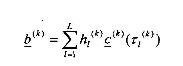
- Each sub matrix B may be written as where the non-zero elements of the k th column, b (k) , of sub-matrix B represent the convolution between the k th user's complex spreading code c (k) (of length Q) and the k th user's propagation channel h (k) or channel estimate (of length W).
- the array of sub-matrices B, one sub-matrix for each user symbol generally arranged along the diagonal of A.
- Figure 1 shows the system matrix for a chip-sampled time slot duration corresponding to N bits per user.
- Each sub matrix B may be written as where the non-zero elements of the k th column, b (k) , of sub-matrix B represent the convolution between the k th user's complex spreading code c (k) (of length Q) and the k th user's propagation channel h (k) or channel estimate (of length W).
- the channel is assumed fixed over a time slot period, and the notation c (k) ( ⁇ 1 (k) ) represents the code c (k) delayed by ⁇ 1 (k)
- a H is the complex transposed skew symmetric representation of the matrix A, and the correlation matrix R is Hermitian. It will be appreciated that other representations of the correlation matrix are possible, and that the present invention does not depend on the precise formulation of the correlation matrix.
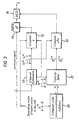
- FIG. 2 The block diagram for a known multi-user-detection receiver, embodying the above considerations, is depicted in Figure 2.
- an incoming signal r is applied to a channel estimation unit 10.
- this forms for each user from an initial training sequence the coefficients h 1 (k) , ⁇ 1 (k) .
- These coefficients are applied to a system matrix computation unit 12, which, together with the user spreading codes c (k) computes the matrix A.
- the complex transposed skew symmetric form of the matrix, AH is applied to a rake filter 14 , having L taps or fingers.
- the incoming signal is modified in rake filter 14 according to A H .
- the modified signal y is applied to multi-user detection unit 16.
- the correlation matrix A H A is computed in unit 18 and applied to MUD unit 16, for recovering the user symbols.
- the signal y applied to MUD unit 16 from rake filter 14 includes cross correlation interference (MAI). It is the task of unit 16 to remove such cross correlations, and derive estimates of the symbols x transmitted by the users.
- MAI cross correlation interference
- MUD unit 16 derives joint estimates of symbols x by simultaneously solving the equations for the signal y , in known manner. It will be noted the present invention is also applicable to the known class of symbol-level subtractive interference cancellation detectors . These create at the receiver separate estimates of the MAI contributed by each user in order to subtract out some or all of the MAI seen by each user. Both in the case of the joint detector and the subtractive interference cancellation detector, computation of the correlation matrix R is necessary.
- unit 20 is provided for computing spreading code cross correlations p prior to initiation of a user call, as will be described more specifically below.
- Only spreading codes of active users are applied to unit 20, and to system matrix unit 12.
- These spreading code cross correlations p are stored in a look up table 22.
- the look up table 22 is accessed by the channel delay values ⁇ 1 (k) , computed by channel estimate unit 10, to provide the appropriate values of cross correlations p to the correlation matrix unit 18.
- unit 18 is relieved of the burden of computing the cross correlation values p during a user call. It will be observed that cross correlation unit 18 requires in addition the values h 1 (k) computed by estimate unit 10. It does not require the system matrix computed in unit 12, in contrast to the arrangement of Figure 2.
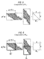
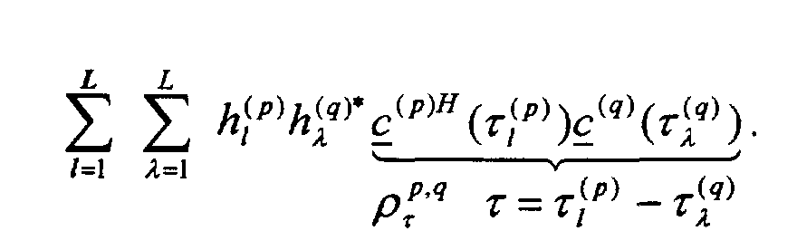
- the effort required for the computation of R isas follows.
- the sub-matrix R 1,1 B H B is Hermitian (see above) .
- the computation of R 1,1 is shown diagrammatically in Figure 5, as multiplication of B with its transposed skew symmetric form.
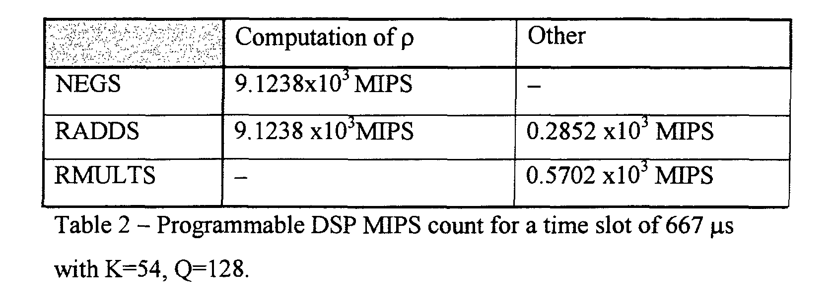
- the MIPS count For implementation on a typical programmable DSP where a negation, real addition and real multiplication are each single-cycle instructions, the MIPS count would be as follows:
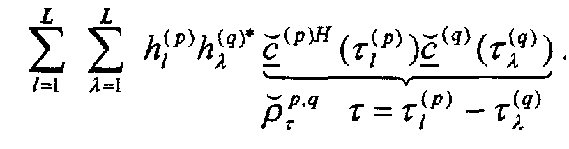
- the sub-matrix R 2,1 equals the inner product of one segment, B 1, of B with a different segment, B 2, of B.
- R 2,1 B H 2
- B 1 [ B ] H 1: Q + W -2,1: K [ B ] Q +1:2 Q + W -2,1: K as depicted in Figure 6.
- B 1 [ B ] H 1: Q + W -2,1: K [ B ] Q +1:2 Q + W -2,1: K as depicted in Figure 6.
- the extent of truncation for each spreading code is a function of the its corresponding channel delays and needs to be accounted for when computing the inner products.
- the matrix R 2,1 is not symmetric and has K 2 unique elements given by where represents a truncated version of v .
- the computation of the R 1,1 and R 2,1 correlation sub-matrices requires the computation of the inner-products between delayed replicas of the user's spreading codes. This is a chip-level operation and, as is evident from Tables (2) and (4), contributes significantly to the overall computational burden. Since the base-station receiver is, by definition, aware of the spreading codes used by the active mobiles in its cell, it is possible, as shown in Figure 3 to compute the inner products off-line prior to the establishment of the communication session. Since the code delays are a function of radio channels which vary significantly during the course of a communication session, it is necessary to pre-compute the inner products for all possible combinations of multipath delays.
- look-up table 22 need only contain the code cross-correlations of the mobiles that have already established dedicated communication channels on the uplink.
- k-1 mobiles stations have already established dedicated communication channels with a BTS (Base Transceiver Station) to provide a signal r .
- BTS Base Transceiver Station
- a repetitive check is made at 72 for a new call originating from a k th mobile via a random-access channel or the BTS initiating a network-originated call via a paging channel targetted at the k th mobile.
- the mobile specifies the nature of its spreading code, c (k) , to the BTS during the call set-up process, as at 74.
- the cross-correlations are stored in look up table 22.
- step 76 during the call, relevant values are accessed from the look up table by addressing the look up table with the delay values ⁇ 1 (k) computed in unit 10, and the retrieved values from the look up table are applied to the correlation matrix unit18. Values of the channel estimate h 1 (k) are applied from estimator unit 10, and the sub matrices R 1,1 , R 2,1 of the correlation matrix are computed, as explained above. The matrix R is then applied to MUD unit 16 to perform multi-user detection of the symbols transmitted by all k mobiles.
- a repetitive check is made at 78 to determine whether the call for user k is terminated. Once the call between the base and user k is determined as terminated as at 80, the cross-correlation values for user k are erased from the look-up table since they are no longer needed.
Landscapes
- Physics & Mathematics (AREA)
- Mathematical Physics (AREA)
- Engineering & Computer Science (AREA)
- Computer Networks & Wireless Communication (AREA)
- Signal Processing (AREA)
- Mobile Radio Communication Systems (AREA)
Abstract
In order to reduce complexity of computation of Multiple Access Interference (MAI) in a
multi-user detection receiver of a mobile telecommunications system, at least some of the
cross- correlations (ρ) between user spreading codes (c) of the correlation matrix are
computed (20) during the call set up process prior to call initiation, and such cross-code
correlations are stored in a look up table (22) for use in calculation of the correlation matrix
during reception of the user signals. The multi-user detection receiver includes means (10)
for forming a channel estimate (h) for each of a plurality of users (1...K), means (12, 14) for
forming a system matrix (A), and applying the system matrix to a rake filter (14) to modify
incoming signals (r), means (18) for forming a correlation matrix (R), and multi-user
detection (MUD) means (16) employing the correlation matrix to recover user symbols. The
invention is applicable both to joint and to symbol-level subtractive interference cancellation
detectors, and more generally to any receiver employing multi-user parameter estimation.
Description
- The present invention relates to Code Division Multiple Access (CDMA) receivers in mobile telecommunications systems, particularly though not exclusively multi-user detection receivers.
- The issues involved in satisfactory reception at a Base Transceiver Station (BTS) of multiple transmissions from mobile stations (MS), modulated with spread spectrum "spreading codes" are well documented, see the following references:
- [1] S. Verdu, "Multiuser Detection", Cambridge University Press, 1998,
ISBN 0 521 59373 5. - [2] S. Moshavi, "Multi-User Detection for DS-CDMA Communications", IEEE Communications Magazine, pp. 124-136, October 1996.
- [3]A. Duel-Hallen, J. Holtzman, Z.Zvonar, "Multiuser Detection for CDMA Systems", IEEE Personal Communications Magazine, pp. 46-58, April 1995.
-
- As appears from these references, the spreading codes are in principle orthogonal, and should not interfere with one another to enable detection by "matched filter" correlation . In practice however for a variety of reasons, e.g. time delay between the various received signals, there exists cross correlation between the received signals - multiple access interference (MAI). This greatly complicates satisfactory reception, the mathematical complexities making an optimal detector impractical. Various approximation techniques have therefore been devised such as decorrelating detectors which applies the inverse of the correlation matrix to the output of the matched filters. Other detectors are the class of linear detectors including the minimum mean-squared error (MMSE) detector, which minimises the mean squared error between the actual data and the soft output of the detector, and the polynomial expansion (PE) detector which applies a polynomial expansion in the correlation matrix to the matched filter bank output. There is also a class of detectors employing subtractive interference cancellation which creates at the receiver separate estimates of the MAI contributed by each user in order to subtract out some or all of the MAI seen by each user. In order to simplify computation, it has been proposed in [1], that knowledge of or processing of cross correlations may be avoided in certain circumstances, and Reference [2] points out with short spreading the partial correlations for each bit can be assumed the same.
- Despite the large number of detectors which have been proposed and implemented, there remains a need for improved detectors for multi-user detection CDMA receivers in mobile telecommunications systems.
- The concept of the present invention is to provide a receiver which enables a significant part of the computation of the correlation matrix to be carried out prior to the establishment of a communications link. This therefore enables a reduced complexity of computation during the reception process, (or alternatively enables use of a more complex algorithm without increasing overall complexity of real-time computation). Thus computational complexity associated with the computation of the correlation matrix in multi-user parameter estimation in a CDMA system, specifically multi-user detection (MUD) CDMA receiver, is reduced.
- A time-sampled signal segment received at a base-transceiver station (BTS)can be written as a vector r = Ax+n where r is the vector of unknown symbols transmitted by all K mobile users in the cell, n is the noise vector. Matrix A is a sparse multi-user "system matrix" whose columns represent the channel-filtered user spreading codes. The objective of multiuser detection is to estimate the vector x of all user symbols, given the received vector r and the matrix A. The implementation of a MUD scheme according to the invention (including joint-detection and symbol-level interference cancellation algorithms) involves the computation of a correlation matrix R=AHA whose elements represent the cross-correlations between various scaled and delayed replicas of the users' spreading codes. The computation of R, which significantly contributes to the overall computational complexity, is reduced by noting in accordance with the invention that the user spreading codes are known a priori at the base station. As a result, the code cross-correlations are computed off-line and stored prior to the establishment of the communication link. The stored values are retrieved in real time to implement the multi-user detection process.
- Thus in a first aspect, the invention provides a Code Division Multiple Access (CDMA) receiver for a mobile telecommunications system, including means for forming a channel estimate for each of a plurality of users, means for forming a system matrix wherein rows and columns represent users and spreading codes as modified by channel estimates , means for forming a correlation matrix, and means employing said correlation matrix and system matrix to recover user symbols, characterised in that said means for forming a correlation matrix includes means for computing prior to signal reception at least some cross-correlations between user spreading codes , and storage means for storing such cross-code correlations for use in calculation of the correlation matrix.
- The invention is applicable in principle to any type of CDMA receiver having a multi-user detector employing a correlation matrix, specifically joint detectors and symbol-level subtractive interference cancellation detectors.
- More generally, the invention relates to reduction of computational complexity of multi-user parameter estimation in CDMA systems, and accordingly the invention provides in a more general aspect, a Code Division Multiple Access receiver for a mobile telecommunications system, including means for multi-user parameter estimation for a plurality of users, including means for forming a correlation matrix, characterised in that said means for forming a correlation matrix includes means for computing prior to signal reception at least some cross- correlations between user spreading codes, and storage means for storing such cross-code correlations for use in calculation of the correlation matrix.
- In a further aspect, the invention provides in a multi-user detection Code Division Multiple Access (CDMA) mobile telecommunications system, a method of receiving individual user signals, comprising:
- forming a multi-user parameter estimation for a plurality of users (1...K), including forming a correlation matrix (R), and employing said correlation matrix to recover user symbols, characterised in that the method comprises detecting a new call, recovering the spreading code for the respective kth mobile station at the base transceiver station (BTS) during the call set-up process;
- computing during the call set-up process cross-correlations between the codes of mobile station k and those of the k-1 mobile stations which have already established calls with the BTS; and
- employing the cross-correlations during the call for reception of the symbols transmitted by all k mobile stations.
-
- A preferred embodiment of the present invention will now be described with reference to the accompanying drawings, wherein:-
- Figure 1 is a diagram of a system matrix employed in the present invention;
- Figure 2 is a block schematic diagram of a known multi-user detection receiver for multi-user CDMA signals;
- Figure 3 is a block schematic diagram of the preferred embodiment of the multi-user detection receiver according to the invention;
- Figure 4 is a diagram of a correlation matrix employed in the present invention;
- Figures 5 and 6 are explanatory diagrams showing the computation of sub-matrices of the correlation matrix; and
- Figure 7 is a flow chart showing a method of call establishment in accordance with the invention.
-
- A time-sampled segment of the signal received at a CDMA base-station can be written as a complex vector r = Ax + n where x is the vector of unknown complex symbols transmitted by all K mobile users in the cell and n is the complex noise vector. The complex matrix A is a multi-user "system matrix" whose columns represent the user spreading codes which are modified by the filtering action of the radio channel.
- Without loss of generality (users may have different spreading factors, i.e. different data rates), consider a scenario as shown in the matrix representation of Figure 1 involving K cochannel asynchronous mobile transmissions each using a spreading factor of Q. The first K columns represent K transmissions of the first symbol, and the nth K columns represent the nth symbol for each of K users. In each column, there is contained the user spreading code as modified by the respective user channel. Thus the system matrix may be represented by an array of sub-matrices B, one sub-matrix for each user symbol, generally arranged along the diagonal of A. Figure 1 shows the system matrix for a chip-sampled time slot duration corresponding to N bits per user. Each sub matrix B may be written aswhere the non-zero elements of the kth column, b (k), of sub-matrix B represent the convolution between the kth user's complex spreading code c (k) (of length Q) and the kth user's propagation channel h (k) or channel estimate (of length W). As is well known in the art, the array of sub-matrices B, one sub-matrix for each user symbol, generally arranged along the diagonal of A. Figure 1 shows the system matrix for a chip-sampled time slot duration corresponding to N bits per user. Each sub matrix B may be written as where the non-zero elements of the kth column, b (k), of sub-matrix B represent the convolution between the kth user's complex spreading code c (k) (of length Q) and the kth user's propagation channel h (k) or channel estimate (of length W). As is well known in the art, the channel h (k) is typically represented by a filter having L taps (or fingers) of complex amplitudes h (k) /
l 1=1...L and delays τ (k) / 1 < τ (k) / 2 < ... < τ (k) / L. The channel is assumed fixed over a time slot period, and the notation c (k) (τ1 (k)) represents the code c (k) delayed by τ1 (k) Many multi-user detection schemes involve the computation of the correlation matrix R=AHA. AH is the complex transposed skew symmetric representation of the matrix A, and the correlation matrix R is Hermitian. It will be appreciated that other representations of the correlation matrix are possible, and that the present invention does not depend on the precise formulation of the correlation matrix. - The block diagram for a known multi-user-detection receiver, embodying the above considerations, is depicted in Figure 2. In figure 2, an incoming signal r is applied to a
channel estimation unit 10. Typically this forms for each user from an initial training sequence the coefficients h1 (k), τ1 (k). These coefficients are applied to a systemmatrix computation unit 12, which, together with the user spreading codes c (k) computes the matrix A. The complex transposed skew symmetric form of the matrix, AH is applied to arake filter 14 , having L taps or fingers. The incoming signal is modified inrake filter 14 according to AH. The modified signal y is applied tomulti-user detection unit 16. The correlation matrix AHA is computed inunit 18 and applied toMUD unit 16, for recovering the user symbols. Thus the signal y applied toMUD unit 16 fromrake filter 14 includes cross correlation interference (MAI). It is the task ofunit 16 to remove such cross correlations, and derive estimates of the symbols x transmitted by the users. - In a joint detection receiver,
MUD unit 16 derives joint estimates of symbols x by simultaneously solving the equations for the signal y, in known manner. It will be noted the present invention is also applicable to the known class of symbol-level subtractive interference cancellation detectors. These create at the receiver separate estimates of the MAI contributed by each user in order to subtract out some or all of the MAI seen by each user. Both in the case of the joint detector and the subtractive interference cancellation detector, computation of the correlation matrix R is necessary. - Referring now to Figure 3, the preferred multi-user detection receiver of the present invention is shown in block schematic form. Similar parts to those of Figure 2 are represented by the same reference numerals. In figure 3,
unit 20 is provided for computing spreading code cross correlations p prior to initiation of a user call, as will be described more specifically below. Only spreading codes of active users are applied tounit 20, and tosystem matrix unit 12. These spreading code cross correlations p are stored in a look up table 22. The look up table 22 is accessed by the channel delay values τ1 (k), computed bychannel estimate unit 10, to provide the appropriate values of cross correlations p to thecorrelation matrix unit 18. Thusunit 18 is relieved of the burden of computing the cross correlation values p during a user call. It will be observed thatcross correlation unit 18 requires in addition the values h1 (k) computed byestimate unit 10. It does not require the system matrix computed inunit 12, in contrast to the arrangement of Figure 2. - In more detail, the correlation matrix of the present invention R=AHA computed in
unit 18 may be represented as shown in Figure 4, wherein sub matrices B in A result in sub matrices in R, comprising matrices R1,1 and cross matrices R2,1 and R2,1 H. The effort required for the computation of R isas follows. - The sub-matrix R 1,1 = B H B is Hermitian (see above) . The computation of R1,1 is shown diagrammatically in Figure 5, as multiplication of B with its transposed skew symmetric form. The resulting coefficients are as shown in the lower diagonal of the matrix, with ½ K(K+1) unique elements given bywhere the computation of each inner product ρ p,q / τ requires an average of ½Q multiply-and-accumulates of the form (±1±j1)(±1±j1) + ... = (±1±1) + j(±1±1) + ... implying a total of ½Q×4 negations (NEGS) and ½Q×4 real additions (RADDS). The computation of each product-and-add h (p) / l × h (q)* / λ × ρ p,q / τ + ... requires 16 real multiplications RMULTS and 8 real additions RADDS. It will be appreciated that NEGS, RADDS and RMULTS are software instructions each of a single machine cycle in a DSP.

The total complexity for computing R1,1 is given by
- For implementation on a typical programmable DSP where a negation, real addition and real multiplication are each single-cycle instructions, the MIPS count would be as follows:
- The sub-matrix R2,1 equals the inner product of one segment, B1, of B with a different segment, B2, of B. Or more specifically
R B where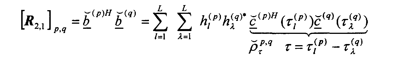 represents a truncated version of v. The computation of each inner product
 requires an average of approximately ½×½Q multiply-and-accumulates of the form (±1± j1)(±1±j1)+ ... = (±1±1) + j(±1±1) + ... implying a total of ½×½Q×4 NEGS and ½×½Q×4 RADDS. The computation of each product-and-add h (p) / l × h (q)* / λ ×
 + ... requires 16 RMULTS and 8 RADDS. The total complexity for computing R2,1 is given by
 For implementation on a typical programmable DSP where a negation, real addition and real multiplication are each single-cycle instructions, the MIPS count would be as follows:

- Thus, the computation of the R1,1 and R2,1 correlation sub-matrices requires the computation of the inner-products between delayed replicas of the user's spreading codes. This is a chip-level operation and, as is evident from Tables (2) and (4), contributes significantly to the overall computational burden. Since the base-station receiver is, by definition, aware of the spreading codes used by the active mobiles in its cell, it is possible, as shown in Figure 3 to compute the inner products off-line prior to the establishment of the communication session. Since the code delays are a function of radio channels which vary significantly during the course of a communication session, it is necessary to pre-compute the inner products for all possible combinations of multipath delays.
- Specifically, regarding R1,1 , the inner products ρ p,q / τ p,q=1...K 1-λ=-(Q-1)...(Q-1) need to be pre-computed and stored in memory look-up table 22. For K users, there are a total of K2 possible combinations of p and q. However, only ½K(K+1) of these are required since R1,1 is symmetric. For each combination of p and q there are 2Q-1 possible relative code delays. The extreme values of the real and imaginary components of ρ p,q / τ are +2Q and -2Q respectively. Then assuming Qmax=128, two 10-bit words are sufficient for storing each value of p resulting in a total memory storage requirement of ½K(K+1) x (2Q-1) x 20 bits. For K=54 and Q=128, this implies ∼ 1Mbytes of memory for the look-up table. This amount of memory provides a saving by a factor of about ×22 in a DSP-based computation of R1,1. Regarding R2,1, the inner productsp,q=1...K 1-λ=-(Q-1)...(Q-1) need to be pre-computed and stored in another region of memory look-up table 22. For K users, there are a total of K2 possible combinations of p and q. For each combination of p and q there are 2Q-1 possible relative code delays (many of whom result in zero inner products due to the truncation, however this will be ignored). The extreme values of the real and imaginary components of

- Note that the look-up table 22 need only contain the code cross-correlations of the mobiles that have already established dedicated communication channels on the uplink.
- A sequence of events for the use of the embodiment of Figure 3 in computation and storage of code cross-correlations is shown in the flow chart of Figure 7, as follows.
- In an
initial step 70, k-1 mobiles stations (MS) have already established dedicated communication channels with a BTS (Base Transceiver Station) to provide a signal r. - A repetitive check is made at 72 for a new call originating from a kth mobile via a random-access channel or the BTS initiating a network-originated call via a paging channel targetted at the kth mobile.
- In either case, the mobile specifies the nature of its spreading code, c (k), to the BTS during the call set-up process, as at 74. The BTS then computes the cross-correlations ρ k,q / τ andq=1...k-1 between the codes of mobile k and those of the k-1 mobiles which have already established dedicated channels with the BTS. The cross-correlations are stored in look up table 22.

- In
step 76, during the call, relevant values are accessed from the look up table by addressing the look up table with the delay values τ1 (k) computed inunit 10, and the retrieved values from the look up table are applied to the correlation matrix unit18. Values of the channel estimate h1 (k) are applied fromestimator unit 10, and the sub matrices R1,1, R2,1 of the correlation matrix are computed, as explained above. The matrix R is then applied toMUD unit 16 to perform multi-user detection of the symbols transmitted by all k mobiles. - A repetitive check is made at 78 to determine whether the call for user k is terminated. Once the call between the base and user k is determined as terminated as at 80, the cross-correlation values for user k are erased from the look-up table since they are no longer needed.
Claims (19)
- A Code Division Multiple Access (CDMA) receiver for a mobile telecommunications system, including means (10-18) for multi-user parameter estimation for a plurality of users (1...K), including means for forming a correlation matrix (R), characterised in that said means for forming a correlation matrix includes means (20) for computing prior to signal reception at least some cross- correlations (p) between user spreading codes (c), and storage means (22) for storing such cross-code correlations for use in calculation of the correlation matrix.
- A multi-user detection Code Division Multiple Access (CDMA) receiver for a mobile telecommunications system, including means (10) for forming a channel estimate (h) for each of a plurality of users (1...K), means (12, 14) for forming a system matrix (A) wherein rows and columns represent users and spreading codes (c) as modified by channel estimates (h), means (18) for forming a correlation matrix (R), and means (14, 16) employing said correlation matrix and system matrix to recover user symbols, characterised in that said means for forming a correlation matrix includes means (20) for computing prior to signal reception at least some cross- correlations (ρ) between user spreading codes (c), and storage means (22) for storing such cross-code correlations for use in calculation of the correlation matrix.
- A receiver according to claim 2, including rake filter means (14) for applying a version of the system matrix to incoming signals (r), and multi-user detection means (16) employing said correlation matrix to recover user symbols
- A receiver according to any preceding claim, wherein the storage means comprises a look-up table (22), and wherein the cross-correlation computing means is arranged to compute all possible cross correlations for storage in the look up table.
- A receiver according to claim 2, wherein the storage means comprises a look-up table (22), and wherein the cross-correlation computing means is arranged to compute all possible cross correlations for storage in the look up table, and wherein the look up table is addressed by said channel estimate means so as to provide cross correlations for estimated channel delays (τ) to said means for forming a correlation matrix.
- A receiver according to claim 2 or 5, wherein said means for forming a correlation matrix is arranged to receive channel estimate coefficients (h) from said means for forming a channel estimate, and is arranged for multiplying these coefficients by the cross-code correlations.
- A receiver according to any preceding claim, wherein the means for forming a correlation matrix is effective to divide the system matrix into submatrices (B), one for each user symbol of a message of N symbols, and wherein each submatrix is multiplied by a version of an adjacent sub matrix to provide a further sub matrix comprising diagonal sections R1,1 and cross sections , R2,1, R2,1 H.
- A receiver according to claim 2, wherein the means for forming a correlation matrix is effective to divide the system matrix into submatrices (B), one for each user symbol of a message of N symbols, and wherein each submatrix is multiplied by a version of an adjacent sub matrix to provide a further sub matrix comprising diagonal sections R11 and cross sections , R21, R21 H, and wherein the storage means is arranged to provide cross correlation coefficients ρ k,q / τ, q=1...k-1, of a diagonal section R11 for channel delay values τ as follows:where h represents channel estimates
- A receiver according to claim 2 or 8, wherein the means for forming a correlation matrix is effective to divide the system matrix into submatrices (B), one for each user symbol of a message of N symbols, and wherein each submatrix is multiplied by a version of an adjacent sub matrix to provide a further sub matrix comprising diagonal sections R11 and cross sections , R21, R21 H, and wherein the storage means is arranged to provide truncated cross correlation coefficientsq=1...k-1, of a cross section R2,1 for channel delay values T as follows
 where h represents channel estimates
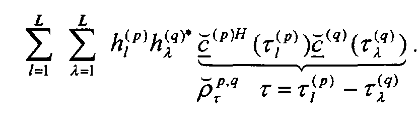
- A receiver according to claim 2, wherein the receiver is a joint detection receiver
- A receiver according to claim 2, wherein the receiver includes a subtractive interference cancellation detector.
- In a multi-user detection Code Division Multiple Access (CDMA) mobile telecommunications system, a method of receiving individual user signals, comprising: forming a multi-user parameter estimation for a plurality of users (1...K), including forming a correlation matrix (R) and employing correlation matrix to recover user symbols, characterised in that the method comprises detecting a new call, recovering the spreading code( c (k))for the respective mobile station (k) at the base transceiver station (BTS) during the call set-up process;computing during the call set-up process cross-correlations (ρ k,q / τ ,
- A method according to claim 12, wherein the new call originates from a kth mobile station via a random-access channel or the BTS initiates a network-originated call via a paging channel targetted at the kth mobile station.
- A method according to claim 12 or 13, including detecting termination of the call, and once the call is terminated, erasing the relevant cross correlation values from the storage means.
- A method according to claim 12, 13 or 14, wherein all possible cross correlations are stored in a look up table (22), and the look up table is addressed by estimated channel delays (τ), so as to provide cross code correlations for forming a correlation matrix.
- A method according to claim 15, wherein the correlation matrix is formed from channel estimate coefficients (h), and multiplying these coefficients by the cross-code correlations.
- A method according to any of claims 12 to 16, wherein the correlation matrix is formed by dividing the system matrix into submatrices (B), one for each user symbol of a message of N symbols, and wherein each submatrix is multiplied by a version of an adjacent sub matrix to provide a further sub matrix comprising diagonal sections R1,1 and cross sections , R2,1, R2,1 H.
- A method according to claim 17, wherein the cross correlation coefficients ρ k,q / τ, q=1...k-1 , of a diagonal section R1,1 for channel delay values τ are as follows:where h represents channel estimates.

- A method according to claim17 or 18, wherein truncated cross correlation coefficients
Priority Applications (1)
| Application Number | Priority Date | Filing Date | Title |
|---|---|---|---|
| EP00301544A EP1128564A1 (en) | 2000-02-28 | 2000-02-28 | Multi-user detection CDMA receivers in mobile telecommunications systems |
Applications Claiming Priority (1)
| Application Number | Priority Date | Filing Date | Title |
|---|---|---|---|
| EP00301544A EP1128564A1 (en) | 2000-02-28 | 2000-02-28 | Multi-user detection CDMA receivers in mobile telecommunications systems |
Publications (1)
| Publication Number | Publication Date |
|---|---|
| EP1128564A1 true EP1128564A1 (en) | 2001-08-29 |
Family
ID=8172741
Family Applications (1)
| Application Number | Title | Priority Date | Filing Date |
|---|---|---|---|
| EP00301544A Withdrawn EP1128564A1 (en) | 2000-02-28 | 2000-02-28 | Multi-user detection CDMA receivers in mobile telecommunications systems |
Country Status (1)
| Country | Link |
|---|---|
| EP (1) | EP1128564A1 (en) |
Cited By (8)
| Publication number | Priority date | Publication date | Assignee | Title |
|---|---|---|---|---|
| WO2002029998A1 (en) * | 2000-09-29 | 2002-04-11 | Matsushita Electric Industrial Co., Ltd. | Demodulator and demodulating method |
| US6466611B1 (en) * | 2001-02-07 | 2002-10-15 | Motorola, Inc. | Multi-user detection using a finite-impulse-response matrix filter |
| JP2010529796A (en) * | 2007-06-14 | 2010-08-26 | テレフオンアクチーボラゲット エル エム エリクソン(パブル) | Efficient calculation of covariance with lookup table |
| EP2560292A1 (en) * | 2011-08-16 | 2013-02-20 | Harris Corporation | CDMA communications device and related methods |
| US8599677B2 (en) * | 2009-05-04 | 2013-12-03 | Qualcomm Incorporated | Method and system for multi-user detection using two-stage processing |
| GB2511079A (en) * | 2013-02-22 | 2014-08-27 | Cascoda Ltd | Transceiver |
| EP2920888A4 (en) * | 2012-11-16 | 2016-08-03 | Ericsson Telefon Ab L M | Efficient generation of spreading sequence correlations using lookup tables |
| WO2019215954A1 (en) * | 2018-05-11 | 2019-11-14 | Mitsubishi Electric Corporation | Communication system, communication method and storage medium |
Citations (4)
| Publication number | Priority date | Publication date | Assignee | Title |
|---|---|---|---|---|
| WO1998038805A2 (en) * | 1997-02-28 | 1998-09-03 | Nokia Mobile Phones Limited | A reception method and a receiver |
| WO1998043362A2 (en) * | 1997-03-26 | 1998-10-01 | D.S.P.C. Technologies Ltd. | Method and apparatus for reducing spread-spectrum noise |
| WO1999001946A1 (en) * | 1997-06-23 | 1999-01-14 | Nokia Networks Oy | Reception method and receiver |
| US6011812A (en) * | 1994-08-25 | 2000-01-04 | Nokia Telecommunications Oy | Receiving method and receiver |
-
2000
- 2000-02-28 EP EP00301544A patent/EP1128564A1/en not_active Withdrawn
Patent Citations (4)
| Publication number | Priority date | Publication date | Assignee | Title |
|---|---|---|---|---|
| US6011812A (en) * | 1994-08-25 | 2000-01-04 | Nokia Telecommunications Oy | Receiving method and receiver |
| WO1998038805A2 (en) * | 1997-02-28 | 1998-09-03 | Nokia Mobile Phones Limited | A reception method and a receiver |
| WO1998043362A2 (en) * | 1997-03-26 | 1998-10-01 | D.S.P.C. Technologies Ltd. | Method and apparatus for reducing spread-spectrum noise |
| WO1999001946A1 (en) * | 1997-06-23 | 1999-01-14 | Nokia Networks Oy | Reception method and receiver |
Non-Patent Citations (1)
| Title |
|---|
| KARIMI H R ET AL: "A novel and efficient solution to block-based joint-detection using approximate Cholesky factorization", IEEE INTERNATIONAL SYMPOSIUM ON PERSONAL, INDOOR AND MOBILE RADIO COMMUNICATIONS,XX,XX, vol. 3, 1998, pages 1340 - 1345-1345vol3, XP002112134 * |
Cited By (15)
| Publication number | Priority date | Publication date | Assignee | Title |
|---|---|---|---|---|
| WO2002029998A1 (en) * | 2000-09-29 | 2002-04-11 | Matsushita Electric Industrial Co., Ltd. | Demodulator and demodulating method |
| US7133467B2 (en) | 2000-09-29 | 2006-11-07 | Matsushita Electric Industrial Co., Ltd. | Demodulation apparatus and demodulation method |
| US6466611B1 (en) * | 2001-02-07 | 2002-10-15 | Motorola, Inc. | Multi-user detection using a finite-impulse-response matrix filter |
| JP2010529796A (en) * | 2007-06-14 | 2010-08-26 | テレフオンアクチーボラゲット エル エム エリクソン(パブル) | Efficient calculation of covariance with lookup table |
| US8229044B2 (en) | 2007-06-14 | 2012-07-24 | Telefonaktiebolaget Lm Ericsson (Publ) | Efficient covariance computation by table lookup |
| US8599677B2 (en) * | 2009-05-04 | 2013-12-03 | Qualcomm Incorporated | Method and system for multi-user detection using two-stage processing |
| EP2560292A1 (en) * | 2011-08-16 | 2013-02-20 | Harris Corporation | CDMA communications device and related methods |
| US9490867B2 (en) | 2011-08-16 | 2016-11-08 | Harris Corporation | CDMA communications device and related methods |
| EP2920888A4 (en) * | 2012-11-16 | 2016-08-03 | Ericsson Telefon Ab L M | Efficient generation of spreading sequence correlations using lookup tables |
| GB2511079A (en) * | 2013-02-22 | 2014-08-27 | Cascoda Ltd | Transceiver |
| GB2511079B (en) * | 2013-02-22 | 2015-05-27 | Cascoda Ltd | Transceiver |
| US9660692B2 (en) | 2013-02-22 | 2017-05-23 | Cascoda Limited | Apparatus and method to perform a double correlation |
| WO2019215954A1 (en) * | 2018-05-11 | 2019-11-14 | Mitsubishi Electric Corporation | Communication system, communication method and storage medium |
| US10498558B1 (en) | 2018-05-11 | 2019-12-03 | Mitsubishi Electric Research Laboratories, Inc. | Symbol detection in shared wireless channel |
| JP2021514599A (en) * | 2018-05-11 | 2021-06-10 | 三菱電機株式会社 | Communication system, communication method and storage medium |
Similar Documents
| Publication | Publication Date | Title |
|---|---|---|
| US7796678B2 (en) | Communication system with receivers employing generalized two-stage data estimation | |
| US6724809B2 (en) | Parallel interference cancellation receiver for multiuser detection of CDMA signals | |
| EP1147620B1 (en) | Apparatus and methods for interference cancellation in spread spectrum communication systems | |
| US6011812A (en) | Receiving method and receiver | |
| EP1987599B1 (en) | Reduced complexity interference suppression for wireless communications | |
| Karimi et al. | A novel and efficient solution to block-based joint-detection using approximate Cholesky factorization | |
| US6600729B1 (en) | DS-CDMA multi-user interference canceller and DS-CDMA Communication system | |
| JP3345406B1 (en) | Wireless receiving apparatus and wireless receiving method | |
| JP4111953B2 (en) | Extended algorithm data estimator | |
| EP1128564A1 (en) | Multi-user detection CDMA receivers in mobile telecommunications systems | |
| US7873098B2 (en) | Robust multicode detector for HSDPA | |
| JP2977019B2 (en) | Dual spread spectrum transmitter and receiver | |
| US8295329B2 (en) | Efficient computation of soft scaling factors for linear multi-user detector | |
| US20040228314A1 (en) | Device for joint detection of cdma codes for multipath downlink | |
| JPWO1995029535A1 (en) | Code division multiplexed signal receiving method | |
| US20080112511A1 (en) | Receiver | |
| Yang et al. | A novel fast joint detector for smart antenna based CDMA systems | |
| JPWO1996000470A1 (en) | Method and apparatus for receiving code division multiplexed signals | |
| HK1064525B (en) | Single user detection | |
| HK1064525A1 (en) | Single user detection |
Legal Events
| Date | Code | Title | Description |
|---|---|---|---|
| PUAI | Public reference made under article 153(3) epc to a published international application that has entered the european phase |
Free format text: ORIGINAL CODE: 0009012 |
|
| AK | Designated contracting states |
Kind code of ref document: A1 Designated state(s): AT BE CH CY DE DK ES FI FR GB GR IE IT LI LU MC NL PT SE |
|
| AX | Request for extension of the european patent |
Free format text: AL;LT;LV;MK;RO;SI |
|
| AKX | Designation fees paid | ||
| REG | Reference to a national code |
Ref country code: DE Ref legal event code: 8566 |
|
| STAA | Information on the status of an ep patent application or granted ep patent |
Free format text: STATUS: THE APPLICATION IS DEEMED TO BE WITHDRAWN |
|
| 18D | Application deemed to be withdrawn |
Effective date: 20020301 |