EP1128502A2 - Optical amplifier using bulk optics - Google Patents
Optical amplifier using bulk optics Download PDFInfo
- Publication number
- EP1128502A2 EP1128502A2 EP00310661A EP00310661A EP1128502A2 EP 1128502 A2 EP1128502 A2 EP 1128502A2 EP 00310661 A EP00310661 A EP 00310661A EP 00310661 A EP00310661 A EP 00310661A EP 1128502 A2 EP1128502 A2 EP 1128502A2
- Authority
- EP
- European Patent Office
- Prior art keywords
- optical
- signal
- block
- pump
- amplified
- Prior art date
- Legal status (The legal status is an assumption and is not a legal conclusion. Google has not performed a legal analysis and makes no representation as to the accuracy of the status listed.)
- Withdrawn
Links
Images


Classifications
-
- H—ELECTRICITY
- H01—ELECTRIC ELEMENTS
- H01S—DEVICES USING THE PROCESS OF LIGHT AMPLIFICATION BY STIMULATED EMISSION OF RADIATION [LASER] TO AMPLIFY OR GENERATE LIGHT; DEVICES USING STIMULATED EMISSION OF ELECTROMAGNETIC RADIATION IN WAVE RANGES OTHER THAN OPTICAL
- H01S3/00—Lasers, i.e. devices using stimulated emission of electromagnetic radiation in the infrared, visible or ultraviolet wave range
- H01S3/05—Construction or shape of optical resonators; Accommodation of active medium therein; Shape of active medium
- H01S3/06—Construction or shape of active medium
- H01S3/0602—Crystal lasers or glass lasers
-
- H—ELECTRICITY
- H01—ELECTRIC ELEMENTS
- H01S—DEVICES USING THE PROCESS OF LIGHT AMPLIFICATION BY STIMULATED EMISSION OF RADIATION [LASER] TO AMPLIFY OR GENERATE LIGHT; DEVICES USING STIMULATED EMISSION OF ELECTROMAGNETIC RADIATION IN WAVE RANGES OTHER THAN OPTICAL
- H01S3/00—Lasers, i.e. devices using stimulated emission of electromagnetic radiation in the infrared, visible or ultraviolet wave range
- H01S3/05—Construction or shape of optical resonators; Accommodation of active medium therein; Shape of active medium
- H01S3/06—Construction or shape of active medium
- H01S3/0602—Crystal lasers or glass lasers
- H01S3/061—Crystal lasers or glass lasers with elliptical or circular cross-section and elongated shape, e.g. rod
-
- H—ELECTRICITY
- H01—ELECTRIC ELEMENTS
- H01S—DEVICES USING THE PROCESS OF LIGHT AMPLIFICATION BY STIMULATED EMISSION OF RADIATION [LASER] TO AMPLIFY OR GENERATE LIGHT; DEVICES USING STIMULATED EMISSION OF ELECTROMAGNETIC RADIATION IN WAVE RANGES OTHER THAN OPTICAL
- H01S3/00—Lasers, i.e. devices using stimulated emission of electromagnetic radiation in the infrared, visible or ultraviolet wave range
- H01S3/05—Construction or shape of optical resonators; Accommodation of active medium therein; Shape of active medium
- H01S3/06—Construction or shape of active medium
- H01S3/063—Waveguide lasers, i.e. whereby the dimensions of the waveguide are of the order of the light wavelength
-
- H—ELECTRICITY
- H01—ELECTRIC ELEMENTS
- H01S—DEVICES USING THE PROCESS OF LIGHT AMPLIFICATION BY STIMULATED EMISSION OF RADIATION [LASER] TO AMPLIFY OR GENERATE LIGHT; DEVICES USING STIMULATED EMISSION OF ELECTROMAGNETIC RADIATION IN WAVE RANGES OTHER THAN OPTICAL
- H01S3/00—Lasers, i.e. devices using stimulated emission of electromagnetic radiation in the infrared, visible or ultraviolet wave range
- H01S3/05—Construction or shape of optical resonators; Accommodation of active medium therein; Shape of active medium
- H01S3/06—Construction or shape of active medium
- H01S3/063—Waveguide lasers, i.e. whereby the dimensions of the waveguide are of the order of the light wavelength
- H01S3/067—Fibre lasers
- H01S3/06708—Constructional details of the fibre, e.g. compositions, cross-section, shape or tapering
-
- H—ELECTRICITY
- H01—ELECTRIC ELEMENTS
- H01S—DEVICES USING THE PROCESS OF LIGHT AMPLIFICATION BY STIMULATED EMISSION OF RADIATION [LASER] TO AMPLIFY OR GENERATE LIGHT; DEVICES USING STIMULATED EMISSION OF ELECTROMAGNETIC RADIATION IN WAVE RANGES OTHER THAN OPTICAL
- H01S3/00—Lasers, i.e. devices using stimulated emission of electromagnetic radiation in the infrared, visible or ultraviolet wave range
- H01S3/05—Construction or shape of optical resonators; Accommodation of active medium therein; Shape of active medium
- H01S3/06—Construction or shape of active medium
- H01S3/063—Waveguide lasers, i.e. whereby the dimensions of the waveguide are of the order of the light wavelength
- H01S3/067—Fibre lasers
- H01S3/06754—Fibre amplifiers
-
- H—ELECTRICITY
- H01—ELECTRIC ELEMENTS
- H01S—DEVICES USING THE PROCESS OF LIGHT AMPLIFICATION BY STIMULATED EMISSION OF RADIATION [LASER] TO AMPLIFY OR GENERATE LIGHT; DEVICES USING STIMULATED EMISSION OF ELECTROMAGNETIC RADIATION IN WAVE RANGES OTHER THAN OPTICAL
- H01S3/00—Lasers, i.e. devices using stimulated emission of electromagnetic radiation in the infrared, visible or ultraviolet wave range
- H01S3/09—Processes or apparatus for excitation, e.g. pumping
- H01S3/091—Processes or apparatus for excitation, e.g. pumping using optical pumping
- H01S3/094—Processes or apparatus for excitation, e.g. pumping using optical pumping by coherent light
-
- H—ELECTRICITY
- H01—ELECTRIC ELEMENTS
- H01S—DEVICES USING THE PROCESS OF LIGHT AMPLIFICATION BY STIMULATED EMISSION OF RADIATION [LASER] TO AMPLIFY OR GENERATE LIGHT; DEVICES USING STIMULATED EMISSION OF ELECTROMAGNETIC RADIATION IN WAVE RANGES OTHER THAN OPTICAL
- H01S3/00—Lasers, i.e. devices using stimulated emission of electromagnetic radiation in the infrared, visible or ultraviolet wave range
- H01S3/14—Lasers, i.e. devices using stimulated emission of electromagnetic radiation in the infrared, visible or ultraviolet wave range characterised by the material used as the active medium
- H01S3/16—Solid materials
- H01S3/1601—Solid materials characterised by an active (lasing) ion
- H01S3/1603—Solid materials characterised by an active (lasing) ion rare earth
- H01S3/1608—Solid materials characterised by an active (lasing) ion rare earth erbium
Definitions
- This invention relates generally to optical amplifiers and more particularly, to an in-line optical amplifier that can be coupled to optical fibre, wherein the amplifying medium has a substantially larger mode field diameter than the optical fibre to which it is coupled.
- rare earth doped fiber amplifiers exhibit low-noise, have relatively large bandwidth with low polarization dependence, substantially reduced crosstalk problems, and low insertion losses at the relevant operating wavelengths which are used in optical communications.
- rare earth doped optical fiber amplifiers can be coupled end-to-end to a transmission fiber, and coupled, through a directional coupler, to a laser diode pump.
- the directional coupler is designed to have a high coupling ratio at the pump wavelength and a low coupling ratio at the signal wavelength so that maximum pump energy is coupled to the amplifier with minimal signal loss.
- the pump energy may be made to propagate either co-directionally or counter-directionally relative to the signal energy, selected for higher power efficiency or better noise performance
- Erbium doped fiber amplifiers operate at 1550 nm which is of particular interest for optical communication systems because, in this wavelength region, the amplifiers exhibit low insertion loss, broad gain bandwidth (approximately 30 nm) and relatively polarization insensitive gain.
- EDFAs Erbium doped fiber amplifiers
- Such amplifiers pumped with light having a wavelength of 980 nm can have a gain as high as 26 dB but require as much as 76 mW of launched pump power. It has generally been desired to achieve a higher gain together with a lower value of pump power coupled into a fiber, and such optimization of EDFAs has been a goal.
- the pump required to launch a signal into a single mode fibre is quite costly.
- the present invention has realized a design to utilize a very high power pump launching a multimoded signal having approximately 1 W of pump power.
- high power optical pump lasers are commercially available at a relatively low cost.
- Such high power pumps are not compatible for use with erbium doped fibre in the manufacture of EDFAs.
- this invention provides a relatively inexpensive optical amplifier that is compatible for use in an optical fibre telecommunications system or for other uses.
- This invention also provides a device that does not require unwieldy lengths of erbium doped fibre to form an amplifier.
- the instant invention uses a block of glass having a mode field diameter orders of magnitude larger than the mode field diameter of erbium doped fibre.
- a cylindrical block of glass having planar ends lends itself to applying coatings or filters thereto, thereby forming selective filters at ends of the erbium doped block to allow the pump light in, and the signal light in at opposite ends, while preventing light at the pump wavelength to propagate out with the amplified signal.
- an optical amplifier comprising: an optical waveguide for carrying an optical signal to be amplified, the optical waveguide having an output end for outcoupling the optical signal;
- an optical amplifier comprising: a first optical waveguide for providing a signal to be amplified, the waveguide having an average mode field diameter d 1 ;
- an optical amplifier for amplifying an incoming optical signal comprising a glass block in the form of a light transmissive medium sized to carry a beam having a mode field diameter of at least 100 ⁇ m, the block being doped with a rare earth for amplifying light passing therethough when the rare earth is excited by a pump beam, the light transmissive medium having a filter at an end thereof for passing the pump beam and for substantially preventing the optical signal to be amplified from passing therethrough, and having a filter at another end thereof, for passing the signal to be amplified and for substantially preventing the pump beam from passing therethrough.
- an optical amplifier comprising:
- a method of amplifying an optical signal comprising the steps of:
- a method of amplifying an optical signal comprising the steps of:
- Rare earth doped fibers for amplifying weak signals for both local and trunk optical telecommunications networks have been of interest for some time now, because of their low insertion loss, broad gain bandwidth and low polarization sensitivity.
- the doped optical fiber is normally coupled to a pump so that a weak optical input signal at some wavelength within the rare earth gain profile experiences a desired amplification.
- Pump light which can be coupled into the optical fiber via a directional coupler may propagate either co-directionally or counter-directionally within the fiber relative to the signal.
- the directional coupler can have a high coupling ratio at the pump wavelength and a low coupling ratio at the signal wavelength.
- the signal experiences loss due to ground state absorption by the rare earth ions.
- the loss due to ground level absorption decreases (i.e., gain is negative but increasing) until, at some value of pump power, there is no net signal absorption (i.e. the gain is zero). This is referred to as the transparency state.
- the pump power in the fiber is increased, a higher proportion of rare earth ions are in their excited state and the stimulated emission from the upper lasing state to the ground state becomes stronger than the absorption from the ground state to the upper lasing state, resulting in a net positive gain at various wavelengths.
- the optical amplifier when pumped so as to populate the upper lasing level, produces a net positive gain above the pump threshold level and the fiber acts as an amplifier.
- Pumping is effected by a separate laser which emits photons of an appropriate energy which is higher than that which corresponds to the signal wavelength.
- the electrons are excited from the ground state to one or more pump bands, which are above the upper lasing level. It is important that the spontaneous lifetime of the upper lasing level exceed that of the pump bands by a significant margin to allow heavy population of the upper level.
- a photon at the laser wavelength interacts with an excited ion in the upper lasing state, stimulated emission can occur.
- the photon can come from either previous spontaneous emission, stimulated emission, or an input signal.
- This invention utilizes a cylindrical block of erbium doped glass as an amplifying medium.
- the cylindrical block has a cross section orders of magnitude greater than the cross section of optical fibre.
- a very high power pump laser is utilized to provide a required amount of energy to the erbium-doped block.
- the mode field diameter of a beam propagating within an optical fibre is expanded to propagate through and traverse the cylindrical block.
- a prior art erbium doped optical fibre amplifier 10 having a pump 12 coupled with an incoming optical signal 20 to be amplified.
- a laser diode 12 provides an output signal having a wavelength of 980 nm that is coupled with an incoming signal 20 to be amplified having a wavelength of 1550 nm.
- a laser diode pump at 1480 nm can alternatively be used.
- a coupler 14 couples the two signals together to be output on a suitable length of erbium doped optical fibre 16.
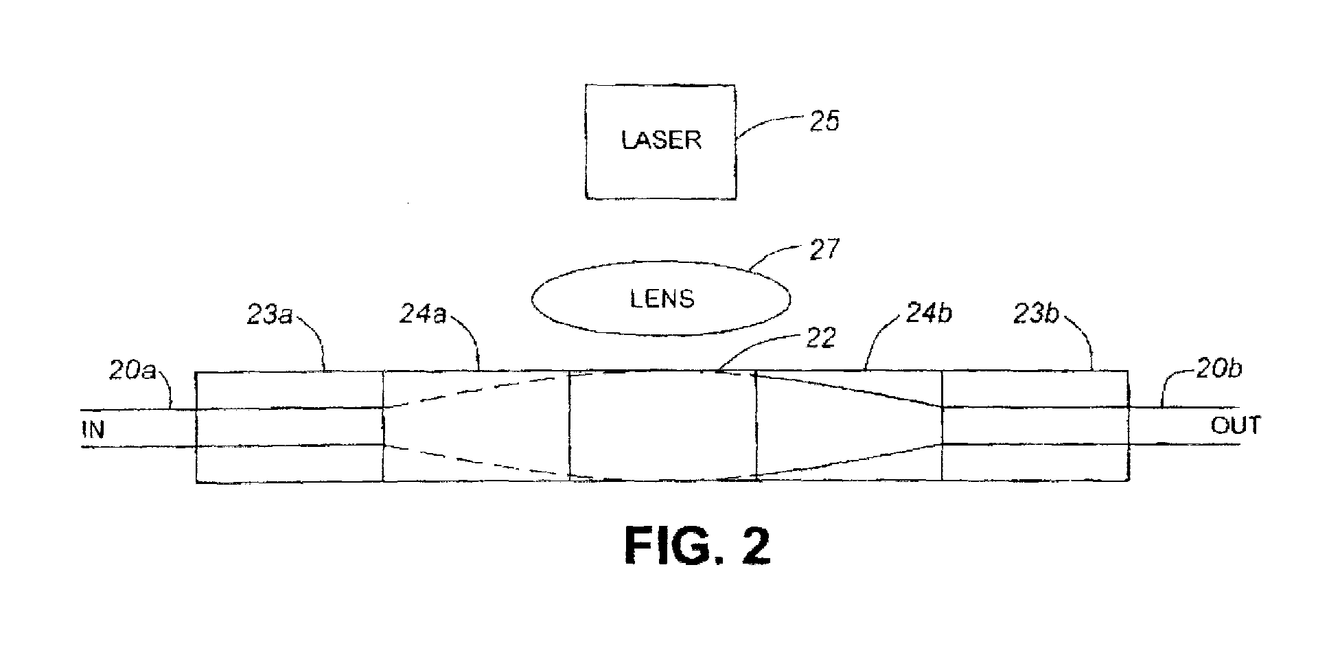
- a block of glass 22 in the form of a rod having a diameter of approximately 350 ⁇ m is shown; the block 22 is doped with erbium.
- a suitable glass is commercially available under the name MM-2, an erbium doped phosphate laser glass produced by Kigre, Inc.. This material includes high dopant percentages and provides high gain.
- a typical length of block 22 required for a net gain of 20 dB is in the range of 1 cm. Notwithstanding, the overall performance depends upon many variables; the same physical principles used in current optical fiber based amplifiers apply.
- the block 22 is disposed between two substantially quarter pitch GRIN lenses 24a and 24b which are disposed between two optical fiber sleeves 23a and 23b housing input optical fibre 20a and output optical fibre 20b.
- a laser 25 optically coupled with the block 22 having a wavelength of 980 nm outputs and pumps the block medium 22 with a high power 1 watt signal that is distributed across and into the block by the lens 27 disposed between the block 22 and the laser 25. As the signal passes through it gains energy from the excited medium 22 and becomes amplified.
- the resulting gain coefficient can reach 22 dB/ cm, given an Er 3+ concentration of 10 21 cm -3 , and emission cross section of 5 x 10 -21 cm 2 .
- FIG. 3 a preferred embodiment of the invention is shown, wherein both input and output optical fibres are coupled into the same end of the device.
- a block 22 similar to the one shown in Fig. 2 is provided having a first optical filter 34 and a second optical filter 32 at opposing ends.
- the filter 34 is designed to pass light having a wavelength of 1550 nm while reflecting light having a wavelength of 980 nm generated by the pump laser.
- the filter 32 is designed to pass light having a wavelength of 980 nm and reflect light incident thereon having a wavelength of 1550 nm.
- the pump laser 38 is optically coupled to the erbium doped block 22 via a lens 24b.
- Both input and output optical fibres 30a and 30b respectively are disposed with an optical fibre ferrule 23 and are coupled optically coupled to the block of rare earth doped medium 22 via a light transmissive spacer element 36 and a GRIN lens 24a.
- the optical path length of the spacer is equal to the optical path length of the block 22, such that the beam traversing both elements traverses equal path lengths.
- a signal light having wavelength 1550 nm is launched from input optical fibre 30a and is collimated to a substantially larger beam with a substantially larger mode field diameter as it traverses the GRIN lens 24a.
- the light then passes through the filter 34 and enters and substantially fills the erbium doped block of glass 22.
- the high power laser 38 provides a pump signal having a wavelength of 980 nm to the block 22 after being substantially collimated by lens 24b.
- Amplified light having a wavelength of 1550 nm is reflected by filter 32 and passed through the filter 34 to couple into the output fibre 30b.
- the filter 34 is not necessary.
- the pump laser 38 can be coupled through a different lens, than a GRIN lens, or no lens at all.
- the rare earth medium 22 can be formed with a taper to a 100 micron diameter and coupled directly to the laser 38.
- additional optical elements can be formed on the block 22, such as diffraction elements or additional filters, or lenses, by etching, depositing or adhering to the end faces of the block 22.
- Input fibres 20a, 30a and output fibres 20b, 30b can advantageously be polarization maintaining fibre pigtails to provide a polarization maintaining amplifier.
- An alternative embodiment of the invention is shown in Fig. 4 wherein two quarter pitch focusing/collimating glass GRIN lenses are doped with erbium and form an optical amplifier.
- a first GRIN lens 44a is coated on an input/output end with a 1550 nm bandpass filter 54; at an opposite end of the lens is a coating 52 that serves as a 980 nm bandpass filter.
- a second lens 44b is disposed directly against the filter 52.
- a laser pump 38 At an outwardly facing end of the second GRIN lens 44b is a laser pump 38; The operation of this device is substantially the same as the amplifier described in Fig. 3, however amplification takes place inside the lens.
- Fig. 5 illustrates the input signal 30a and output signal 30b launched at a small angle, for instance of approximately 1.5 degrees in order to easily separate the input signal from the output signal.
- the amplifying medium 122 can be formed to provide waveguiding for the pump energy without guiding the signal Coating the block 22, for example with a metal cladding 120 will keep pump light within the block to assist in inducing the maximum pump light absorption.
- the pump source 38 coupled directly to the metal cladded block 122 total internal reflection causes the pump light to reflect from the sidewalls within the block 122.
- a collimating lens 124 coupling the laser pump 38 to the block 122, an expanded beam of pump light is launched through the medium 122.
- multiple groups of input and output fibres 130, 230 can be disposed to amplify more than one signal at a time, as shown in Fig. 7.
- a larger block diameter is required to prevent the multiple signal beams from overlapping and interacting within the block 222.
Landscapes
- Physics & Mathematics (AREA)
- Electromagnetism (AREA)
- Chemical & Material Sciences (AREA)
- Crystallography & Structural Chemistry (AREA)
- Engineering & Computer Science (AREA)
- Plasma & Fusion (AREA)
- Optics & Photonics (AREA)
- Lasers (AREA)
- Optical Communication System (AREA)
Abstract
Description
An alternative embodiment of the invention is shown in Fig. 4 wherein two quarter pitch focusing/collimating glass GRIN lenses are doped with erbium and form an optical amplifier. A
Claims (16)
- An optical amplifier comprising:a first optical waveguide for providing a signal to be amplified, the waveguide having an average mode field diameter d1;a second optical waveguide optically coupled with the first waveguide for receiving the signal after it has been amplified, the second waveguide having a mode field diameter d2, where d1 and d2 are substantially smaller than d3;a light transmissive amplifying medium for guiding a beam having a mode field diameter of at least d3, said light transmissive amplifying medium being disposed to receive light from the first optical waveguide and to provide amplified light to the second optical waveguide;a pump optically coupled with the light transmissive amplifying medium for providing pump energy to the amplifying medium.
- An optical amplifier as defined in claim 1, wherein the light transmissive amplifying medium is a block of glass, doped with a rare earth element.
- An optical amplifier as defined in claim 2, wherein the glass block is sized to carry a beam having a mode field diameter of at least 100µm, the block having a filter at an end thereof for passing the pump beam and for substantially preventing the optical signal to be amplified from passing therethrough, and having a filter at another end thereof, for passing the signal to be amplified and for substantially preventing the pump beam from passing therethrough.
- An optical amplifier as defined in claim 3, wherein one of the filters disposed adjacent the pump has a pass band at a central wavelength of the pump energy, and wherein the other of the filters disposed adjacent the first and second waveguides has a pass band at a wavelength corresponding to a wavelength of the signal to be amplified.
- An optical amplifier as defined in claim 4, further comprising a lens disposed between the two waveguides and the filter having a passband corresponding to the wavelength of the signal to be amplified for providing collimated light having an expanded mode field to the block and for providing a focused beam to the second waveguide.
- An optical amplifier as defined in claim 3, wherein the light transmissive medium includes a coating to promote total internal reflection within the medium.
- An optical amplifier as defined in claim 3, wherein the block of glass is provided with means for maintaining or varying the temperature of the block.
- An optical amplifier as defined in claim 2, wherein the glass block has optical power.
- An optical amplifier as defined in claim 8, wherein the glass block has a graded index forming a lens.
- An optical amplifier as defined in claim 3, further comprising an optical element formed on an end of the glass block selected from at least one of : a diffraction element, a lens, and a filter.
- An optical amplifier as defined in claim 5 further comprising optical fibres disposed to provide light to and receive amplified light from the end of the glass block having the filter that prevents the pump beam from passing therethrough.
- An optical amplifier as defined in claim 11, wherein the fibres are polarization maintaining fibres.
- An optical amplifier as defined in claim 11 wherein the lens for substantiallly expanding a mode field diameter is a GRIN lens and wherein the input optical fibre and the output optical fibre are both housed within a ferrule, the amplifier further comprising a light transmissive spacer element disposed between the ferrule and the GRIN lens.
- An optical amplifier as defined in claim 13, further comprising a lens disposed between the pump source and the pump medium for substantially collimating pump light from the pump source.
- An optical amplifier comprising:an optical waveguide for carrying an optical signal to be amplified, the optical waveguide having an output end for launching the optical signal;a substantially collimating lens optically coupled with the output end of the optical waveguide for receiving the optical signal and for providing a substantially collimated beam to be amplified, the substantially collimated beam having a substantially larger mode field diameter than the optical signal being carried by the optical waveguide;a block of light transmissive material sized to carry the substantially collimated beam for amplification, the block of light transmissive material being comprised of a gain medium doped with a rare-earth element, the block being disposed to receive the substantially collimated optical beam; and,a high power pump disposed to impart optical energy to the block; and, an output optical waveguide disposed to couple focused light of the optical signal after it has been amplified within the block of light transmissive material.
- A method of amplifying an optical signal comprising the steps of:launching a beam carrying the optical signal from an optical fibre;substantially increasing a mode field diameter of the beam and providing the beam to an amplifying medium;pumping optical energy having a different wavelength from the optical signal into the amplifying medium, and receiving an amplified optical signal from the amplifying medium and,decreasing the mode field diameter of the amplified signal and coupling the amplified signal to an output optical fibre.
Applications Claiming Priority (2)
| Application Number | Priority Date | Filing Date | Title |
|---|---|---|---|
| US16839199P | 1999-12-02 | 1999-12-02 | |
| US168391 | 1999-12-02 |
Publications (2)
| Publication Number | Publication Date |
|---|---|
| EP1128502A2 true EP1128502A2 (en) | 2001-08-29 |
| EP1128502A3 EP1128502A3 (en) | 2004-04-28 |
Family
ID=22611320
Family Applications (1)
| Application Number | Title | Priority Date | Filing Date |
|---|---|---|---|
| EP00310661A Withdrawn EP1128502A3 (en) | 1999-12-02 | 2000-11-30 | Optical amplifier using bulk optics |
Country Status (4)
| Country | Link |
|---|---|
| US (1) | US6433927B1 (en) |
| EP (1) | EP1128502A3 (en) |
| CN (1) | CN1198175C (en) |
| CA (1) | CA2326980A1 (en) |
Cited By (4)
| Publication number | Priority date | Publication date | Assignee | Title |
|---|---|---|---|---|
| US6433927B1 (en) * | 1999-12-02 | 2002-08-13 | Jds Uniphase Inc. | Low cost amplifier using bulk optics |
| FR2827969A1 (en) * | 2001-07-26 | 2003-01-31 | Get Enst Bretagne | OPTICAL DEVICE COMPRISING MODE EXPANSION FIBERS FOR IMPLEMENTING AT LEAST ONE OPTICAL FUNCTION, AND CORRESPONDING OPTICAL SYSTEM |
| EP1487070A1 (en) * | 2003-06-13 | 2004-12-15 | Furukawa Electric North America Inc. (a Delaware Corporation) | Cladding-pumped optical fiber gain devices |
| EP1950852A2 (en) * | 2007-01-26 | 2008-07-30 | Furukawa Electric North America Inc. (a Delaware Corporation) | High power optical apparatus employing large-mode-area, multimode, gain-producing optical fibers |
Families Citing this family (17)
| Publication number | Priority date | Publication date | Assignee | Title |
|---|---|---|---|---|
| FR2815421B1 (en) * | 2000-10-16 | 2003-09-19 | France Telecom | OPTICAL COLLIMATOR FOR SINGLE-MODE FIBERS, SINGLE-MODE FIBER WITH INTEGRATED COLLIMATOR AND MANUFACTURING METHOD |
| US6624925B2 (en) * | 2001-03-13 | 2003-09-23 | Textron Systems Corporation | Optical amplifier employing an active doped unitary amplifier |
| JP3826726B2 (en) * | 2001-04-25 | 2006-09-27 | 日本電気株式会社 | Optical output device protection device, optical transmission system using the same, and optical output device protection method |
| JP3941531B2 (en) * | 2002-02-07 | 2007-07-04 | 住友電気工業株式会社 | Optical receiver module |
| US7194209B1 (en) * | 2002-09-04 | 2007-03-20 | Xantech Corporation | Interference resistant infrared extension system |
| DE202007017386U1 (en) * | 2007-12-13 | 2008-02-28 | CCS Technology, Inc., Wilmington | Coupling device for coupling optical waveguides |
| US8218593B2 (en) * | 2008-07-24 | 2012-07-10 | Alliant Techsystems Inc. | Optical devices comprising doped glass materials, laser systems including such optical devices, and methods of forming such optical devices and laser systems |
| CN104603655A (en) * | 2012-08-29 | 2015-05-06 | 柯尼卡美能达株式会社 | Optical fiber coupling member and method for producing same |
| US20140160482A1 (en) * | 2012-12-07 | 2014-06-12 | The General Hospital Corporation | Optical system for endoscopic internally-referenced interferometric imaging, and method for employing the same |
| JP5928570B1 (en) * | 2014-12-22 | 2016-06-01 | 東洋製罐グループホールディングス株式会社 | Optical coupler and optical coupling method for optical fiber with GRIN lens |
| JP6955307B2 (en) | 2018-11-06 | 2021-10-27 | 富士フイルム株式会社 | Imaging lens and imaging device |
| CN110764248B (en) * | 2019-09-26 | 2021-09-24 | 浙江大学 | A probe with optimized depth of focus, working distance and axial intensity uniformity |
| CN111628396A (en) * | 2020-05-08 | 2020-09-04 | 武汉光迅科技股份有限公司 | Optical amplifier |
| US20230258965A1 (en) * | 2020-07-09 | 2023-08-17 | National University Of Singapore | Method and device for optical power limiter |
| US20230161119A1 (en) * | 2021-11-24 | 2023-05-25 | Cisco Technology, Inc. | Multiconfiguration isolator wavelength division multiplexer |
| WO2023102769A1 (en) * | 2021-12-08 | 2023-06-15 | Lumentum Operations Llc | Multiple filter package configuration for wavelength division multiplexer |
| CN114678759A (en) * | 2022-03-23 | 2022-06-28 | 深圳市欧凌镭射科技有限公司 | Fiber-coupled crystal structures and gain devices |
Family Cites Families (25)
| Publication number | Priority date | Publication date | Assignee | Title |
|---|---|---|---|---|
| US4553238A (en) * | 1983-09-30 | 1985-11-12 | The Board Of Trustees Of The Leland Stanford University | Fiber optic amplifier |
| US4837771A (en) * | 1985-05-01 | 1989-06-06 | Spectra-Physics, Inc. | High-efficiency mode-matched solid-state laser with transverse pumping and cascaded amplifier stages |
| JPH0271345A (en) * | 1988-09-07 | 1990-03-09 | Sharp Corp | Ic card |
| JPH0327027A (en) * | 1989-06-26 | 1991-02-05 | Oki Electric Ind Co Ltd | Optical amplifier |
| JPH03156693A (en) * | 1989-11-15 | 1991-07-04 | Hitachi Ltd | automatic cash transaction device |
| DE4104268A1 (en) * | 1991-02-13 | 1992-08-20 | Standard Elektrik Lorenz Ag | FIBER OPTICAL AMPLIFIER |
| US5295209A (en) * | 1991-03-12 | 1994-03-15 | General Instrument Corporation | Spontaneous emission source having high spectral density at a desired wavelength |
| FR2675592B1 (en) * | 1991-04-22 | 1993-07-16 | Alcatel Nv | OPTICAL AMPLIFIER IN THE SPECTRAL AREA 1.26 TO 1.34 MUM. |
| JP2955780B2 (en) * | 1991-06-27 | 1999-10-04 | 三菱電線工業株式会社 | Optical fiber amplifier |
| US5293438A (en) * | 1991-09-21 | 1994-03-08 | Namiki Precision Jewel Co., Ltd. | Microlensed optical terminals and optical system equipped therewith, and methods for their manufacture, especially an optical coupling method and optical coupler for use therewith |
| US5530709A (en) * | 1994-09-06 | 1996-06-25 | Sdl, Inc. | Double-clad upconversion fiber laser |
| WO1996019743A1 (en) * | 1994-12-21 | 1996-06-27 | E-Tek Dynamics, Inc. | Integrable fiberoptic coupler and resulting devices and systems |
| US5717517A (en) * | 1995-01-13 | 1998-02-10 | The Research Foundation Of City College Of New York | Method for amplifying laser signals and an amplifier for use in said method |
| JPH08234046A (en) * | 1995-02-24 | 1996-09-13 | Kyocera Corp | Optical components |
| JPH0951136A (en) * | 1995-08-04 | 1997-02-18 | Hitachi Ltd | Optical amplifier |
| JP2000505595A (en) * | 1996-02-13 | 2000-05-09 | オプティカル コーポレーション オブ アメリカ | External cavity semiconductor laser with monolithic prism assembly |
| JP3530951B2 (en) * | 1996-03-29 | 2004-05-24 | 株式会社日立コミュニケーションテクノロジー | Optical fiber, optical amplifier and optical transmission system |
| US5719973A (en) * | 1996-07-30 | 1998-02-17 | Lucent Technologies Inc. | Optical waveguides and components with integrated grin lens |
| JPH10162779A (en) * | 1996-11-29 | 1998-06-19 | Toshiba Lighting & Technol Corp | Ceramic discharge lamp, lamp device, lighting device, and liquid crystal projector |
| UA47454C2 (en) * | 1996-12-20 | 2002-07-15 | Научний Центр Волоконной Оптікі Прі Інстітутє Общєй Фізікі Россійской Акадєміі Наук | Fiber converter of the mode field diameter, method for local chanche of the refractive index of the optical waveguides and a method for preparing raw stock for optical waveguides |
| US6088500A (en) * | 1997-04-11 | 2000-07-11 | Trw Inc. | Expanded mode wave guide semiconductor modulation |
| US5818630A (en) * | 1997-06-25 | 1998-10-06 | Imra America, Inc. | Single-mode amplifiers and compressors based on multi-mode fibers |
| US6031849A (en) * | 1997-11-14 | 2000-02-29 | Jds Uniphase Corporation | High power three level fiber laser and method of making same |
| US6301421B1 (en) * | 1999-05-27 | 2001-10-09 | Trw Inc. | Photonic crystal fiber lasers and amplifiers for high power |
| CA2326980A1 (en) * | 1999-12-02 | 2001-06-02 | Jds Uniphase Inc. | Low cost amplifier using bulk optics |
-
2000
- 2000-11-28 CA CA002326980A patent/CA2326980A1/en not_active Abandoned
- 2000-11-29 US US09/725,129 patent/US6433927B1/en not_active Expired - Fee Related
- 2000-11-30 EP EP00310661A patent/EP1128502A3/en not_active Withdrawn
- 2000-12-01 CN CNB001344625A patent/CN1198175C/en not_active Expired - Fee Related
Cited By (6)
| Publication number | Priority date | Publication date | Assignee | Title |
|---|---|---|---|---|
| US6433927B1 (en) * | 1999-12-02 | 2002-08-13 | Jds Uniphase Inc. | Low cost amplifier using bulk optics |
| FR2827969A1 (en) * | 2001-07-26 | 2003-01-31 | Get Enst Bretagne | OPTICAL DEVICE COMPRISING MODE EXPANSION FIBERS FOR IMPLEMENTING AT LEAST ONE OPTICAL FUNCTION, AND CORRESPONDING OPTICAL SYSTEM |
| EP1487070A1 (en) * | 2003-06-13 | 2004-12-15 | Furukawa Electric North America Inc. (a Delaware Corporation) | Cladding-pumped optical fiber gain devices |
| EP2086069A2 (en) | 2003-06-13 | 2009-08-05 | Furukawa Electric North America Inc. (a Delaware Corporation) | Cladding-pumped optical fiber gain devices |
| EP2086069A3 (en) * | 2003-06-13 | 2009-08-19 | Furukawa Electric North America Inc. (a Delaware Corporation) | Cladding-pumped optical fiber gain devices |
| EP1950852A2 (en) * | 2007-01-26 | 2008-07-30 | Furukawa Electric North America Inc. (a Delaware Corporation) | High power optical apparatus employing large-mode-area, multimode, gain-producing optical fibers |
Also Published As
| Publication number | Publication date |
|---|---|
| US6433927B1 (en) | 2002-08-13 |
| CN1311455A (en) | 2001-09-05 |
| CA2326980A1 (en) | 2001-06-02 |
| CN1198175C (en) | 2005-04-20 |
| US20020063952A1 (en) | 2002-05-30 |
| EP1128502A3 (en) | 2004-04-28 |
Similar Documents
| Publication | Publication Date | Title |
|---|---|---|
| US6433927B1 (en) | Low cost amplifier using bulk optics | |
| US6608951B1 (en) | Optical fiber amplifiers and lasers and optical pumping device therefor | |
| JP2971561B2 (en) | Erbium-doped fiber amplifier | |
| JP2933998B2 (en) | Erbium-doped fiber amplifier coupling device | |
| US5027079A (en) | Erbium-doped fiber amplifier | |
| US6903865B2 (en) | Communication system using S-band Er-doped fiber amplifiers with depressed cladding | |
| EP0812039B1 (en) | Fiber light source with multimode fiber coupler | |
| US5966480A (en) | Article comprising an improved cascaded optical fiber Raman device | |
| JP2786725B2 (en) | Optical fiber and fiber optical active device | |
| US5287216A (en) | Fiber amplifier with multiple pumps | |
| US5283846A (en) | Optical isolator, optical circuit, and rare-earth-doped fiber optical amplifier | |
| JPH07181529A (en) | Optical-fiber amplification system | |
| KR100900793B1 (en) | Gain clamped amplifier using double clad fiber | |
| JPH05509202A (en) | optical waveguide amplifier | |
| AU644087B2 (en) | A fiber optical amplifier | |
| US5633964A (en) | Article comprising a multi-stage erbium-doped fiber amplifier | |
| EP0700137B1 (en) | 1.06 um band fiber optical amplifier | |
| JPH06102546A (en) | Optical communication system having power limiter for high energy pulse | |
| KR100269170B1 (en) | Optical amplifier using optical fiber reflector | |
| JP2740676B2 (en) | Optical amplification transmission circuit | |
| KR100219711B1 (en) | Optical fiber amplifier with flat gain property | |
| JP2006505117A (en) | Optical amplifier | |
| JPH06324368A (en) | Optical fiber amplifier | |
| JP3029303B2 (en) | Multi-fiber optical amplifier and connection structure of multi-core optical fiber using the same | |
| KR100327299B1 (en) | Fiber-optic amplifier using a 2-port wavelength selective coupler |
Legal Events
| Date | Code | Title | Description |
|---|---|---|---|
| PUAI | Public reference made under article 153(3) epc to a published international application that has entered the european phase |
Free format text: ORIGINAL CODE: 0009012 |
|
| AK | Designated contracting states |
Kind code of ref document: A2 Designated state(s): AT BE CH CY DE DK ES FI FR GB GR IE IT LI LU MC NL PT SE TR |
|
| AX | Request for extension of the european patent |
Free format text: AL;LT;LV;MK;RO;SI |
|
| PUAL | Search report despatched |
Free format text: ORIGINAL CODE: 0009013 |
|
| AK | Designated contracting states |
Kind code of ref document: A3 Designated state(s): AT BE CH CY DE DK ES FI FR GB GR IE IT LI LU MC NL PT SE TR |
|
| AX | Request for extension of the european patent |
Extension state: AL LT LV MK RO SI |
|
| STAA | Information on the status of an ep patent application or granted ep patent |
Free format text: STATUS: THE APPLICATION IS DEEMED TO BE WITHDRAWN |
|
| 18D | Application deemed to be withdrawn |
Effective date: 20040601 |