EP1128492A2 - Modular jack connector - Google Patents
Modular jack connector Download PDFInfo
- Publication number
- EP1128492A2 EP1128492A2 EP01103773A EP01103773A EP1128492A2 EP 1128492 A2 EP1128492 A2 EP 1128492A2 EP 01103773 A EP01103773 A EP 01103773A EP 01103773 A EP01103773 A EP 01103773A EP 1128492 A2 EP1128492 A2 EP 1128492A2
- Authority
- EP
- European Patent Office
- Prior art keywords
- modular jack
- board
- connector
- jack connector
- plug
- Prior art date
- Legal status (The legal status is an assumption and is not a legal conclusion. Google has not performed a legal analysis and makes no representation as to the accuracy of the status listed.)
- Withdrawn
Links
Images





Classifications
-
- H—ELECTRICITY
- H01—ELECTRIC ELEMENTS
- H01R—ELECTRICALLY-CONDUCTIVE CONNECTIONS; STRUCTURAL ASSOCIATIONS OF A PLURALITY OF MUTUALLY-INSULATED ELECTRICAL CONNECTING ELEMENTS; COUPLING DEVICES; CURRENT COLLECTORS
- H01R12/00—Structural associations of a plurality of mutually-insulated electrical connecting elements, specially adapted for printed circuits, e.g. printed circuit boards [PCB], flat or ribbon cables, or like generally planar structures, e.g. terminal strips, terminal blocks; Coupling devices specially adapted for printed circuits, flat or ribbon cables, or like generally planar structures; Terminals specially adapted for contact with, or insertion into, printed circuits, flat or ribbon cables, or like generally planar structures
- H01R12/70—Coupling devices
- H01R12/71—Coupling devices for rigid printing circuits or like structures
- H01R12/712—Coupling devices for rigid printing circuits or like structures co-operating with the surface of the printed circuit or with a coupling device exclusively provided on the surface of the printed circuit
- H01R12/716—Coupling device provided on the PCB
-
- H—ELECTRICITY
- H01—ELECTRIC ELEMENTS
- H01R—ELECTRICALLY-CONDUCTIVE CONNECTIONS; STRUCTURAL ASSOCIATIONS OF A PLURALITY OF MUTUALLY-INSULATED ELECTRICAL CONNECTING ELEMENTS; COUPLING DEVICES; CURRENT COLLECTORS
- H01R24/00—Two-part coupling devices, or either of their cooperating parts, characterised by their overall structure
- H01R24/60—Contacts spaced along planar side wall transverse to longitudinal axis of engagement
- H01R24/62—Sliding engagements with one side only, e.g. modular jack coupling devices
- H01R24/64—Sliding engagements with one side only, e.g. modular jack coupling devices for high frequency, e.g. RJ 45
Definitions
- the present invention relates to modular jack connectors into which modular plug connectors are plugged and, particularly, to a surface mount type modular jack connector that is mounted on the surface of a board.
- Connectors have been used in telephone equipment or local area network (LAN).
- LAN local area network
- Tt usually is mounted on a board and plugged with a modular plug connector to which a cable or a plurality of core wires are connected.
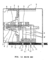
- Fig. 11 shows a conventional modular jack connector 1 mounted on a board 10.
- the connector 1 comprises a housing 2, a plurality of wire terminals 3 and 3', a terminal holder 4 for holding the terminals 3 and 3', and a shield sheet 5 for covering the housing 2.
- a plurality of plug cavities 6 and 6' are arranged side-by-side in upper and lower rows so that a plurality of modular plug connectors (not shown) can be plugged into the plug cavities 6 and 6' respectively.
- the terminals 3 and 3' arc cantilevered and comprised of a resilient contact section 7 or 7', a plug side section 8 or 8' supported by the housing 2 and extending in the plugging direction of the modular plug connector, and a board side section 9 or 9' extending downwardly from the plug side sections 8 or 8'. They are arranged in a direction perpendicular to the plane of the drawing (hereinafter "fist direction") in the number corresponding to that of the plug connector; e.g., eight for each of the upper and lower tiers.
- the contact sections 7 and 7' are brought into contact with the terminals of the plug connector so that the plug connectors are electrically connected to the jack connector 1.
- the board side sections 9 and 9' are supported by the terminal holder 4 at regular intervals.
- the end portions 11 and 11' of the board side sections 9 and 9' are inserted into the attaching holes 12 of the board 10 and soldered to circuit traces of the board 10.
- the terminals 3 and 3' of the modular jack connector 1 must be arranged in a zigzag fashion to provide a predetermined distance between the terminals to not only prevent cross-talk but also provide a soldering space. For this reason, the depth of the modular jack connector is increased by that much, preventing miniaturization of the modular jack connector. Also, this zigzag arrangement makes it difficult to use a robot for automatic assembling.
- the end portions 11 and 11' of the soldered terminals project from the board 10 limit arrangement design choices of electronics components to be mounted.
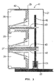
- a modular jack connector 21 comprises a connector body 22 and a surface mount connector 24 to be mounted on a board 23.
- the connector body 22 comprises a housing 25 of an insulation material and a plurality of terminals 26 and 26' provided in Lhe housing 25.
- a shield plate 27 covers the housing 25 to shield noise from the outside.
- a shield plate 27' is provided between the terminals 26 and 26' Lo shield them.
- a plurality of upper and lower plug cavities 28 and 28' are arranged in the housing 25 in the first direction to receive modular plug connectors (not shown).
- Each upper terminal 26 has a plug side section 29 extending in the plugging direction along the bottom of the upper plug cavity 28, a board side section 30 extending downwardly from the plug side section 29, and a contact section 31 extending diagonally rearwardly from the plug side section 29.
- Each lower terminal 26' has a plug side section 29' extending along the ceiling of the lower plug cavity 28' in the plugging direction, a board side section 30' extending downwardly from the plug side section 29', and a contact section 31' extending diagonally rearwardly from the plug side section 29'.
- eight contact sections 31 or 31' are arranged in the upper or lower plug cavity 28 or 28' in the first direction with a predetermined pitch corresponding to the terminals of a modular plug connector. Consequently, when a modular plug connector is plugged into the plug cavity 28 or 28', the contact sections 31 or 31' are brought. into contact with the terminals of the modular plug connector to electrically connect the modular plug connector with the modular jack connector 21.
- the eight board side sections 30 are arranged with a predetermined pitch in the first direction and bonded to a surface 33 of a core member 32 made of a sheet of an insulation material.
- the eight board side sections 30' of the lower plug cavity 28' are arranged in the first direction with a predetermined pitch and bonded to the other surface 34 of the core member 32. That is, 16 terminals 26 and 26' of the upper and lower plug cavities 28 and 28' are united by the core member 32, with the shield plate 27' provided in the center of the core member 32.
- the surface mount connector 24 extends in the first direction and has the form of a trench into or from which the lower portions of the board side sections 30 and 30' are plugged or unplugged.
- Tt comprises a housing 35 of an insulation material and 16 contact terminals 36 and 36' corresponding Lo Lhe board side sections 30 and 30'.
- the upper portion of each contact terminal 36 or 36' is bent to provide an inwardly convex contact section 37 or 37' for holding the board side sections 30 or 31' under a predetermined pressure to electrically connect the terminal 26 or 26' with the contact terminal 36 or 36'.
- the lower portions of the contact terminals 36 and 36' extend in opposite directions to provide leg sections 38 and 38', which are mounted on a surface of the board 23 for electrical connection with predetermined traces of the board 23.
- the terminals 26 and 26' are united, simply by plugging the board side sections 30 and 30' into the surface mounted connector 24, it is possible to connect the terminals 26 and 26' to the surface mount connector 24. Not only impedance match is made between the plug side and board side sections 28, 29' and 30, 30' of the terminals 26, 26' but. also cross-talk is prevented. Since it is not necessary to separate the terminals 26 and 26' at the predetormined distance, the depth of the modular jack connector 41 is reduced, making miniaturization of the modular jack connector possible.
- the surface mount connector 24 is placed on the board 23 at a predetermined circuit position by a robot (not shown) and the leg sections 38 and 38' are soldered to predetermined circuit traces of the board 23 so that the surface mount connector 24 is not only electrically connected to the predetermined circuit traces but also mechanically fixed to the board 23.
- the surface mount connector 24 has such a size and weight that the robot can hold it, and the mounting operation can be made in the same direction relative to the board 23 so Lhat it is easy to automate the mounting operation of the surface mount connector 24, thus making labor saving possible.
- the lower portions of the board side sections 30 and 30' are plugged into the surface mount connector 24 to electrically connect the connector body 22 to the surface mount connector 24. Since the contact sections 37 and 37' of the surface mount connector 24 hold the terminals 26 and 26' therebetween under the predetermined pressure, the connector body 22 is secured to the board 23 via the surface mount connector 24.
- the upper and lower plug cavities 28 and 28' may be replaced by a single tier or at least three Lier plug cavities. Where the plug cavities are provided at least three tiers, it is preferred to unite the termials 26 in every two adjacent tiers.
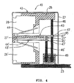
- a modular jack connector 41 comprising a connector body 42 and the surface mount connector 24.
- the connector body 42 comprising the housing 25 and a plurality of terminals 43 and 43', and the shield plate 27 to cover Lhe housing 25.
- the terminals 43 and 43' are arranged corresponding to the upper and lower plug cavities 28 and 28' that are arranged in the first direction.
- Each upper terminal 43 has a horizontal section provided on the housing 25 and a cantilevered contact section 44 extending diagonally rearwardly.
- Each lower terminal 43' has a horizontal section provided on the housing 25 and a contact section 44' extending diagonally rearwardly.
- the shape of the terminal 43 and 43' is so simple that there is no need for complicated bending work, resulting in the labor saving.
- connection board 46 extends in the first direction and a direction normal to the board 23 (hereinafter "second direction"), and the lower end portion thereof is pluggable into the surface mount connector 24.
- the predetermined circuit is provided on the connection board 46, and the contact terminals 36 and 36' arc provided in the surface mount connector 24 to hold the lower end portion of the connection board 46 under a predetermined pressure for electrical connection with the connection board 46.
- a shield plate 27' is provided between the terminals 43 and 43', with an end portion 27'' inserted into an aperture 47" of the connection board 46 and soldered to a circuit trace of the connection board 46 for electrical connection.
- connection board 46 is plugged into the surface mount connector 24 for connection so that: il. is very easy to connect them. Not only impedance match of the terminals 43, 43' and the connection board 46 is made but also the cross-talk is prevented. In addition, since the connection board 46 is thin, the depth of the modular jack connector 41 is reduced, resulting in the compact modular jack connector 41.
- the surface mount connector 24 is mounted on the board 23 by a robot (not shown) for electric connection with a predetermined circuit trace of the board 23. Then, the lower end portion of the connection board 46 is plugged into the surface mount connector 24 for electrical connection between the connector body 42 and the surface mount connector 24. Since the contact sections 37 and 37' of the surface mount connector 24 hold the connection board 46 under the predetermined pressure so that the connector body 42 is secured to the board 23 via the surface mount connector 24.
- the upper and lower plug cavities 28 and 28' of the second cmbodiment are replaced by three-tier plug cavities 28.
- they may be a single or at least four-tier plug cavities.
- the terminals 43 and 43' are connected to separate connection boards 46 and 46', respectively, and the shield plate 27' is connected to only the connection plate 46'.
- the surface mount connector 49 is comprised of a pair of the surface mount connectors integrated as a unit.
- a shield layer 50 of copper or the like is deposited on the outside or inside of the connection board 46 and connected at the upper end with the shield plate 27 for ground connection.
- the portion of the shield plate 27 opposed to the connection board 46 may be omitted. Not only the depth of the modular jack connector 41 is reduced but also the ground connection is made easy.
- the shield layer 50 may be deposited on only the outside of the outermost connection board.
- connection between the shield plate 27 and the shield layer 50 may be made by inserting an end of the shield plate 27 into a hole of the connection board 46 and soldering it to the connection board 46.
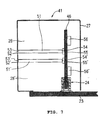
- an indicator equipped connector displays light from a light source, such as a light emission diode (LED), to indicate plugging or signal receiving conditions of the modular jack connector from the modular plug connector.
- a light source such as a light emission diode (LED)
- LED light emission diode
- It comprises a light pipe 51 made of a transparent material, such as a transparent resin, and extends horizontally or in the plugging direction through the upper portion of the housing 25.
- An indicator opening 52 is provided at Lhe upper portion of the plug cavity 28 to expose an end 53 of the light pipe 51.
- An LED 55 is mounted on the connection board 46 at a position opposed to and spaced from the other end 54 of the light pipe 51 and emits light horizontally toward the other end 54.
- the connection board 46 is removable so that it is easy to replace the LED 55.
- a noise filter 56 is surface mounted on the connection board 46 on the surface opposite Lo the LED for preventing interference by the noise. The light goes straight from the LED 55 to the outside through the light pipe 51 and the indicator opening 52. The noise produced within the circuitry is removed by the noise filter 56.
- two-tier plug cavities 28 and 28' are provided in contrast to the single-tier plug cavity 28 of Fig. 6.
- Fig. 8 the third embodiment. of the invention is shown, wherein the same or similar components to those of the first or second cmbodiment are assigned with the same reference numerals and their description is omitted.
- the end portions 45 and 45' of terminals 43 and 43' of a modular jack connector 61 are inserted into and electrically connected to a flat flexible cable 62.
- the end portion 27" of the shield plate 27' is also inserted into and electrically connected to the flexible cable 62.
- the lower portion of the flexible cable 62 is bent toward the outside of the shield plate 27 and electrically connected to a predetermined circuit trace of the board 23 via a surface mount connector 63.
- the surface mount connector 63 is soldered to the board 23 by a robot (not shown) for electrical connection with a predetermined circuit trace and, then, the lower portion of the flexible cable 62 is connected to the surface mount connector 63.
- the two-tier plug cavities 28 and 28' may be replace by a single or at. least three tiers of plug cavities.
- the surface mount connector 63 may be mounted on the board 23 inside of the shield plate 27 as shown by phantom line in Fig. 8. A portion of the shield plate 27 may be replaced by a shield layer that is deposited on the flexible cable 62 and connected to the shield plate 27 at the upper end.
- a modular jack connector 71 comprises a connector body 72 and the surface mount connector 24.
- the connector body 72 comprises a housing 73, a plurality of terminals 74 provided in the housing 73, and the shield plate 27 to cover the housing 73.
- a plug cavity 75 is provided in the housing 73 to receive a modular plug connector (not shown) in the second direction.
- the terminal 74 are arranged in the plug cavity 75 and each have a plug side section 76 extending in the plugging direction on the housing, a board side section 77 extending from the plug side section 76 in parallel to the board 23, and a cantilevered contact section 78 extending diagonally from the plug side section 76.
- the end portion of the board side section 77 is inserted into the hole 47 of the connection board 46 and electrically connected to a circuit trace of the connection board 46.
- the surface mount connector 24 is mounted on the board 23 by a robot (not shown) for electrical connection with a predetermined electrical circuit of the board 23 and, then, the lower end portion of the connection board 46 is plugged into the surface mount connector 24.
- a shield layer of copper or the like may be deposited on the outside or inside of the connection board 46 and connected to the shield plate 27 for ground connection.
- the portion of the shield plate 27 opposed to the connection hoard 46 may be omitted, making riot only reduction of the depth of the modular jack connector 71 possible but also the ground connection easy.
- a plurality of modular jack connectors 41 of the first, second, third, or fourth embodiment are surface mounted on both sides of the board 23 at positions symmetric relative to the board 23, for example.
- the number of terminals 26, 43, or 74 is not limited to the above illustrated embodiments.
- the modular jack connector can be mounted on the surface of a board so that there are many choices in circuit design for the modular jack connector or the other electronics components.
Landscapes
- Coupling Device And Connection With Printed Circuit (AREA)
- Details Of Connecting Devices For Male And Female Coupling (AREA)
Abstract
Description
Claims (13)
- A modular jack connector mountable on a board, comprising:a connector body including at least one plug cavity in at least one tier to receive a modular plug connector and at least one terminal for contact with at least one contact terminal of said modular plug connector; anda surface mount connector, whereinsaid at least one terminal of said connector body is electrically connected to said board via said surface mount connector.
- A modular jack connector according to claim 1, wherein said at least one terminal is directly connected to said surface mount connector.
- A modular jack connector according to claim 2, wherein a plurality of said terminals in a plurality of said plug cavities are integrated in adjacent upper and lower tiers as a unit.
- A modular jack connector according to claim 2 or 3, wherein impedance match is made between plug and board side sections of said at least one terminal.
- A modular jack connector according to claim 1, which further comprises at least one connection board for connecting said at least one terminal and said surface mount connector.
- A modular jack connector according to claim 5, wherein said terminals in a plurality of said tiers are connected to said connection board.
- A modular jack connector according to claim 5, wherein said terminals in a plurality of said tires are connected to a plurality of said connection boards; one tier for each connection board.
- A modular jack connector according to claim 5, 6, or 7, which further comprises a shield layer deposited on said at. least one connection board and electrically connected to said shield plate that covers said housing.
- A modular jack connector according to claim 5, 6, or 7, wherein impedance match is made in said connection board.
- A modular jack connector according to claim 1, which further comprises at least one flexible flat cable that connects said at least one terminal and said surface mount connector.
- A modular jack connector according to claim 10, wherein said terminals in a plurality of said tiers are connected to said flat cable.
- A modular jack connector according to claim 10, wherein said terminals in a plurality of said tiers are connected to a plurality of said flat cables; one tier for each flat cable.
- A modular jack connector according to claim 1, 5, or 10, wherein said modular jack connector is mountable on either side of said board.
Applications Claiming Priority (2)
| Application Number | Priority Date | Filing Date | Title |
|---|---|---|---|
| JP2000036303 | 2000-02-15 | ||
| JP2000036303A JP4455711B2 (en) | 2000-02-15 | 2000-02-15 | Modular jack connector |
Publications (2)
| Publication Number | Publication Date |
|---|---|
| EP1128492A2 true EP1128492A2 (en) | 2001-08-29 |
| EP1128492A3 EP1128492A3 (en) | 2002-01-30 |
Family
ID=18560363
Family Applications (1)
| Application Number | Title | Priority Date | Filing Date |
|---|---|---|---|
| EP01103773A Withdrawn EP1128492A3 (en) | 2000-02-15 | 2001-02-15 | Modular jack connector |
Country Status (4)
| Country | Link |
|---|---|
| US (1) | US20010014563A1 (en) |
| EP (1) | EP1128492A3 (en) |
| JP (1) | JP4455711B2 (en) |
| TW (1) | TW478667U (en) |
Cited By (1)
| Publication number | Priority date | Publication date | Assignee | Title |
|---|---|---|---|---|
| EP3575672A4 (en) * | 2017-05-24 | 2020-05-13 | Suzhou Opple Lighting Co., Ltd. | ELECTRICAL CONNECTION MODULE AND LAMP ASSEMBLY |
Families Citing this family (16)
| Publication number | Priority date | Publication date | Assignee | Title |
|---|---|---|---|---|
| US7182649B2 (en) * | 2003-12-22 | 2007-02-27 | Panduit Corp. | Inductive and capacitive coupling balancing electrical connector |
| US7179131B2 (en) * | 2004-02-12 | 2007-02-20 | Panduit Corp. | Methods and apparatus for reducing crosstalk in electrical connectors |
| CN102082367B (en) | 2004-03-12 | 2013-11-20 | 泛达公司 | Methods and apparatus for reducing crosstalk in electrical connectors |
| US7153168B2 (en) * | 2004-04-06 | 2006-12-26 | Panduit Corp. | Electrical connector with improved crosstalk compensation |
| US7281957B2 (en) * | 2004-07-13 | 2007-10-16 | Panduit Corp. | Communications connector with flexible printed circuit board |
| JP2006278288A (en) * | 2005-03-30 | 2006-10-12 | Fujitsu Ltd | Connector mounting structure |
| EP1987569A1 (en) * | 2006-02-13 | 2008-11-05 | Panduit Corp. | Connector with crosstalk compensation |
| US7874878B2 (en) | 2007-03-20 | 2011-01-25 | Panduit Corp. | Plug/jack system having PCB with lattice network |
| JP4599373B2 (en) * | 2007-05-31 | 2010-12-15 | 日本航空電子工業株式会社 | Socket connector and plug connector |
| US7967644B2 (en) * | 2009-08-25 | 2011-06-28 | Tyco Electronics Corporation | Electrical connector with separable contacts |
| US8016621B2 (en) | 2009-08-25 | 2011-09-13 | Tyco Electronics Corporation | Electrical connector having an electrically parallel compensation region |
| US8435082B2 (en) | 2010-08-03 | 2013-05-07 | Tyco Electronics Corporation | Electrical connectors and printed circuits having broadside-coupling regions |
| JP5910682B2 (en) | 2014-08-08 | 2016-04-27 | Smk株式会社 | Electrical connector |
| JP6292201B2 (en) * | 2015-09-18 | 2018-03-14 | Smk株式会社 | Electrical connector |
| EP3387715B1 (en) | 2015-12-08 | 2021-05-12 | Panduit Corp. | Rj45 shuttered jacks and related communication systems |
| JP7419146B2 (en) * | 2020-04-09 | 2024-01-22 | 日本航空電子工業株式会社 | Connectors and electronic equipment |
Family Cites Families (3)
| Publication number | Priority date | Publication date | Assignee | Title |
|---|---|---|---|---|
| DE3903418C1 (en) * | 1989-02-06 | 1990-01-18 | Telenorma Telefonbau Und Normalzeit Gmbh, 6000 Frankfurt, De | Socket for an electrical connector |
| US5562504A (en) * | 1995-01-04 | 1996-10-08 | Simple Technology Incorporated | Communications card with integral transmission media line adaptor |
| US6022245A (en) * | 1998-05-29 | 2000-02-08 | The Whitaker Corporation | Filtered modular connector |
-
2000
- 2000-02-15 JP JP2000036303A patent/JP4455711B2/en not_active Expired - Fee Related
- 2000-05-26 TW TW089208966U patent/TW478667U/en not_active IP Right Cessation
-
2001
- 2001-02-14 US US09/782,205 patent/US20010014563A1/en not_active Abandoned
- 2001-02-15 EP EP01103773A patent/EP1128492A3/en not_active Withdrawn
Cited By (1)
| Publication number | Priority date | Publication date | Assignee | Title |
|---|---|---|---|---|
| EP3575672A4 (en) * | 2017-05-24 | 2020-05-13 | Suzhou Opple Lighting Co., Ltd. | ELECTRICAL CONNECTION MODULE AND LAMP ASSEMBLY |
Also Published As
| Publication number | Publication date |
|---|---|
| US20010014563A1 (en) | 2001-08-16 |
| EP1128492A3 (en) | 2002-01-30 |
| TW478667U (en) | 2002-03-01 |
| JP2001230027A (en) | 2001-08-24 |
| JP4455711B2 (en) | 2010-04-21 |
Similar Documents
| Publication | Publication Date | Title |
|---|---|---|
| US20010014563A1 (en) | Modular jack connector | |
| JP3153260U (en) | Cable connector | |
| US6165006A (en) | Cable connector | |
| US6478611B1 (en) | Electrical connector with visual indicator | |
| US7674136B2 (en) | Modular jack connector system | |
| US6478610B1 (en) | Electrical connector assembly | |
| TWI424630B (en) | Modular electrical connector with enhanced jack interface | |
| US6431906B1 (en) | Modular connectors with detachable line status indicators | |
| US7281957B2 (en) | Communications connector with flexible printed circuit board | |
| US6224417B1 (en) | Assembly containing a modular jack and a light emitting diode | |
| US5915993A (en) | Assembly containing a modular jack and a light emitting diode | |
| TWI442650B (en) | Electrical connector | |
| US6083047A (en) | Modular electrical PCB assembly connector | |
| JP3416650B2 (en) | Modular electrical connector assembly with magnetic filter and / or visual indicator | |
| US4695115A (en) | Telephone connector with bypass capacitor | |
| US4863393A (en) | Modular jack assembly with improved bridging arrangement | |
| US20110306244A1 (en) | Cable connector assembly having an adapter plate for grounding | |
| JP3484606B2 (en) | Electrical connector having optical transmission module | |
| EP0852414A2 (en) | Connector with integrated PCB assembly | |
| KR20080105155A (en) | Electrical connector with contact plate | |
| US10653000B2 (en) | Electrical connector assembly capable of transmitting high-frequency signals | |
| US5667401A (en) | Cable connector, circuit board and system having circuit boards connected together by the cable connector | |
| US20110263157A1 (en) | Electrical connector grounding path to outer shell | |
| CN100508302C (en) | Coupling sleeve for making a high power data line link and use of a socket for making such coupling sleeve | |
| US6439922B1 (en) | Visual indicators having common cathode leads, and an electrical connector using same |
Legal Events
| Date | Code | Title | Description |
|---|---|---|---|
| PUAI | Public reference made under article 153(3) epc to a published international application that has entered the european phase |
Free format text: ORIGINAL CODE: 0009012 |
|
| AK | Designated contracting states |
Kind code of ref document: A2 Designated state(s): AT BE CH CY DE DK ES FI FR GB GR IE IT LI LU MC NL PT SE TR |
|
| AX | Request for extension of the european patent |
Free format text: AL;LT;LV;MK;RO;SI |
|
| PUAL | Search report despatched |
Free format text: ORIGINAL CODE: 0009013 |
|
| AK | Designated contracting states |
Kind code of ref document: A3 Designated state(s): AT BE CH CY DE DK ES FI FR GB GR IE IT LI LU MC NL PT SE TR |
|
| AX | Request for extension of the european patent |
Free format text: AL;LT;LV;MK;RO;SI |
|
| RIC1 | Information provided on ipc code assigned before grant |
Free format text: 7H 01R 24/04 A, 7H 01R 31/06 B |
|
| AKX | Designation fees paid | ||
| REG | Reference to a national code |
Ref country code: DE Ref legal event code: 8566 |
|
| STAA | Information on the status of an ep patent application or granted ep patent |
Free format text: STATUS: THE APPLICATION IS DEEMED TO BE WITHDRAWN |
|
| 18D | Application deemed to be withdrawn |
Effective date: 20020731 |