CN102082367B - Methods and apparatus for reducing crosstalk in electrical connectors - Google Patents
Methods and apparatus for reducing crosstalk in electrical connectors Download PDFInfo
- Publication number
- CN102082367B CN102082367B CN2010105369067A CN201010536906A CN102082367B CN 102082367 B CN102082367 B CN 102082367B CN 2010105369067 A CN2010105369067 A CN 2010105369067A CN 201010536906 A CN201010536906 A CN 201010536906A CN 102082367 B CN102082367 B CN 102082367B
- Authority
- CN
- China
- Prior art keywords
- socket
- zone
- crosstalk compensation
- contact
- compensation devices
- Prior art date
- Legal status (The legal status is an assumption and is not a legal conclusion. Google has not performed a legal analysis and makes no representation as to the accuracy of the status listed.)
- Active
Links
Images


Classifications
-
- H—ELECTRICITY
- H01—ELECTRIC ELEMENTS
- H01R—ELECTRICALLY-CONDUCTIVE CONNECTIONS; STRUCTURAL ASSOCIATIONS OF A PLURALITY OF MUTUALLY-INSULATED ELECTRICAL CONNECTING ELEMENTS; COUPLING DEVICES; CURRENT COLLECTORS
- H01R24/00—Two-part coupling devices, or either of their cooperating parts, characterised by their overall structure
- H01R24/60—Contacts spaced along planar side wall transverse to longitudinal axis of engagement
- H01R24/62—Sliding engagements with one side only, e.g. modular jack coupling devices
- H01R24/64—Sliding engagements with one side only, e.g. modular jack coupling devices for high frequency, e.g. RJ 45
-
- H—ELECTRICITY
- H01—ELECTRIC ELEMENTS
- H01R—ELECTRICALLY-CONDUCTIVE CONNECTIONS; STRUCTURAL ASSOCIATIONS OF A PLURALITY OF MUTUALLY-INSULATED ELECTRICAL CONNECTING ELEMENTS; COUPLING DEVICES; CURRENT COLLECTORS
- H01R12/00—Structural associations of a plurality of mutually-insulated electrical connecting elements, specially adapted for printed circuits, e.g. printed circuit boards [PCB], flat or ribbon cables, or like generally planar structures, e.g. terminal strips, terminal blocks; Coupling devices specially adapted for printed circuits, flat or ribbon cables, or like generally planar structures; Terminals specially adapted for contact with, or insertion into, printed circuits, flat or ribbon cables, or like generally planar structures
- H01R12/50—Fixed connections
- H01R12/59—Fixed connections for flexible printed circuits, flat or ribbon cables or like structures
- H01R12/592—Fixed connections for flexible printed circuits, flat or ribbon cables or like structures connections to contact elements
-
- H—ELECTRICITY
- H01—ELECTRIC ELEMENTS
- H01R—ELECTRICALLY-CONDUCTIVE CONNECTIONS; STRUCTURAL ASSOCIATIONS OF A PLURALITY OF MUTUALLY-INSULATED ELECTRICAL CONNECTING ELEMENTS; COUPLING DEVICES; CURRENT COLLECTORS
- H01R12/00—Structural associations of a plurality of mutually-insulated electrical connecting elements, specially adapted for printed circuits, e.g. printed circuit boards [PCB], flat or ribbon cables, or like generally planar structures, e.g. terminal strips, terminal blocks; Coupling devices specially adapted for printed circuits, flat or ribbon cables, or like generally planar structures; Terminals specially adapted for contact with, or insertion into, printed circuits, flat or ribbon cables, or like generally planar structures
- H01R12/50—Fixed connections
- H01R12/59—Fixed connections for flexible printed circuits, flat or ribbon cables or like structures
- H01R12/65—Fixed connections for flexible printed circuits, flat or ribbon cables or like structures characterised by the terminal
- H01R12/67—Fixed connections for flexible printed circuits, flat or ribbon cables or like structures characterised by the terminal insulation penetrating terminals
- H01R12/675—Fixed connections for flexible printed circuits, flat or ribbon cables or like structures characterised by the terminal insulation penetrating terminals with contacts having at least a slotted plate for penetration of cable insulation, e.g. insulation displacement contacts for round conductor flat cables
-
- H—ELECTRICITY
- H01—ELECTRIC ELEMENTS
- H01R—ELECTRICALLY-CONDUCTIVE CONNECTIONS; STRUCTURAL ASSOCIATIONS OF A PLURALITY OF MUTUALLY-INSULATED ELECTRICAL CONNECTING ELEMENTS; COUPLING DEVICES; CURRENT COLLECTORS
- H01R12/00—Structural associations of a plurality of mutually-insulated electrical connecting elements, specially adapted for printed circuits, e.g. printed circuit boards [PCB], flat or ribbon cables, or like generally planar structures, e.g. terminal strips, terminal blocks; Coupling devices specially adapted for printed circuits, flat or ribbon cables, or like generally planar structures; Terminals specially adapted for contact with, or insertion into, printed circuits, flat or ribbon cables, or like generally planar structures
- H01R12/70—Coupling devices
- H01R12/77—Coupling devices for flexible printed circuits, flat or ribbon cables or like structures
- H01R12/771—Details
- H01R12/775—Ground or shield arrangements
-
- H—ELECTRICITY
- H01—ELECTRIC ELEMENTS
- H01R—ELECTRICALLY-CONDUCTIVE CONNECTIONS; STRUCTURAL ASSOCIATIONS OF A PLURALITY OF MUTUALLY-INSULATED ELECTRICAL CONNECTING ELEMENTS; COUPLING DEVICES; CURRENT COLLECTORS
- H01R13/00—Details of coupling devices of the kinds covered by groups H01R12/70 or H01R24/00 - H01R33/00
- H01R13/46—Bases; Cases
- H01R13/502—Bases; Cases composed of different pieces
-
- H—ELECTRICITY
- H01—ELECTRIC ELEMENTS
- H01R—ELECTRICALLY-CONDUCTIVE CONNECTIONS; STRUCTURAL ASSOCIATIONS OF A PLURALITY OF MUTUALLY-INSULATED ELECTRICAL CONNECTING ELEMENTS; COUPLING DEVICES; CURRENT COLLECTORS
- H01R13/00—Details of coupling devices of the kinds covered by groups H01R12/70 or H01R24/00 - H01R33/00
- H01R13/646—Details of coupling devices of the kinds covered by groups H01R12/70 or H01R24/00 - H01R33/00 specially adapted for high-frequency, e.g. structures providing an impedance match or phase match
- H01R13/6461—Means for preventing cross-talk
- H01R13/6464—Means for preventing cross-talk by adding capacitive elements
- H01R13/6466—Means for preventing cross-talk by adding capacitive elements on substrates, e.g. printed circuit boards [PCB]
-
- H—ELECTRICITY
- H01—ELECTRIC ELEMENTS
- H01R—ELECTRICALLY-CONDUCTIVE CONNECTIONS; STRUCTURAL ASSOCIATIONS OF A PLURALITY OF MUTUALLY-INSULATED ELECTRICAL CONNECTING ELEMENTS; COUPLING DEVICES; CURRENT COLLECTORS
- H01R13/00—Details of coupling devices of the kinds covered by groups H01R12/70 or H01R24/00 - H01R33/00
- H01R13/646—Details of coupling devices of the kinds covered by groups H01R12/70 or H01R24/00 - H01R33/00 specially adapted for high-frequency, e.g. structures providing an impedance match or phase match
- H01R13/6461—Means for preventing cross-talk
- H01R13/6467—Means for preventing cross-talk by cross-over of signal conductors
-
- H—ELECTRICITY
- H01—ELECTRIC ELEMENTS
- H01R—ELECTRICALLY-CONDUCTIVE CONNECTIONS; STRUCTURAL ASSOCIATIONS OF A PLURALITY OF MUTUALLY-INSULATED ELECTRICAL CONNECTING ELEMENTS; COUPLING DEVICES; CURRENT COLLECTORS
- H01R13/00—Details of coupling devices of the kinds covered by groups H01R12/70 or H01R24/00 - H01R33/00
- H01R13/66—Structural association with built-in electrical component
- H01R13/719—Structural association with built-in electrical component specially adapted for high frequency, e.g. with filters
-
- H—ELECTRICITY
- H01—ELECTRIC ELEMENTS
- H01R—ELECTRICALLY-CONDUCTIVE CONNECTIONS; STRUCTURAL ASSOCIATIONS OF A PLURALITY OF MUTUALLY-INSULATED ELECTRICAL CONNECTING ELEMENTS; COUPLING DEVICES; CURRENT COLLECTORS
- H01R4/00—Electrically-conductive connections between two or more conductive members in direct contact, i.e. touching one another; Means for effecting or maintaining such contact; Electrically-conductive connections having two or more spaced connecting locations for conductors and using contact members penetrating insulation
- H01R4/24—Connections using contact members penetrating or cutting insulation or cable strands
- H01R4/2416—Connections using contact members penetrating or cutting insulation or cable strands the contact members having insulation-cutting edges, e.g. of tuning fork type
- H01R4/242—Connections using contact members penetrating or cutting insulation or cable strands the contact members having insulation-cutting edges, e.g. of tuning fork type the contact members being plates having a single slot
- H01R4/2425—Flat plates, e.g. multi-layered flat plates
- H01R4/2429—Flat plates, e.g. multi-layered flat plates mounted in an insulating base
-
- H—ELECTRICITY
- H05—ELECTRIC TECHNIQUES NOT OTHERWISE PROVIDED FOR
- H05K—PRINTED CIRCUITS; CASINGS OR CONSTRUCTIONAL DETAILS OF ELECTRIC APPARATUS; MANUFACTURE OF ASSEMBLAGES OF ELECTRICAL COMPONENTS
- H05K1/00—Printed circuits
- H05K1/02—Details
- H05K1/0213—Electrical arrangements not otherwise provided for
- H05K1/0216—Reduction of cross-talk, noise or electromagnetic interference
- H05K1/0228—Compensation of cross-talk by a mutually correlated lay-out of printed circuit traces, e.g. for compensation of cross-talk in mounted connectors
-
- H—ELECTRICITY
- H05—ELECTRIC TECHNIQUES NOT OTHERWISE PROVIDED FOR
- H05K—PRINTED CIRCUITS; CASINGS OR CONSTRUCTIONAL DETAILS OF ELECTRIC APPARATUS; MANUFACTURE OF ASSEMBLAGES OF ELECTRICAL COMPONENTS
- H05K1/00—Printed circuits
- H05K1/02—Details
- H05K1/0277—Bendability or stretchability details
- H05K1/028—Bending or folding regions of flexible printed circuits
-
- H—ELECTRICITY
- H01—ELECTRIC ELEMENTS
- H01R—ELECTRICALLY-CONDUCTIVE CONNECTIONS; STRUCTURAL ASSOCIATIONS OF A PLURALITY OF MUTUALLY-INSULATED ELECTRICAL CONNECTING ELEMENTS; COUPLING DEVICES; CURRENT COLLECTORS
- H01R12/00—Structural associations of a plurality of mutually-insulated electrical connecting elements, specially adapted for printed circuits, e.g. printed circuit boards [PCB], flat or ribbon cables, or like generally planar structures, e.g. terminal strips, terminal blocks; Coupling devices specially adapted for printed circuits, flat or ribbon cables, or like generally planar structures; Terminals specially adapted for contact with, or insertion into, printed circuits, flat or ribbon cables, or like generally planar structures
- H01R12/50—Fixed connections
- H01R12/59—Fixed connections for flexible printed circuits, flat or ribbon cables or like structures
- H01R12/62—Fixed connections for flexible printed circuits, flat or ribbon cables or like structures connecting to rigid printed circuits or like structures
-
- H—ELECTRICITY
- H01—ELECTRIC ELEMENTS
- H01R—ELECTRICALLY-CONDUCTIVE CONNECTIONS; STRUCTURAL ASSOCIATIONS OF A PLURALITY OF MUTUALLY-INSULATED ELECTRICAL CONNECTING ELEMENTS; COUPLING DEVICES; CURRENT COLLECTORS
- H01R13/00—Details of coupling devices of the kinds covered by groups H01R12/70 or H01R24/00 - H01R33/00
- H01R13/66—Structural association with built-in electrical component
- H01R13/665—Structural association with built-in electrical component with built-in electronic circuit
- H01R13/6658—Structural association with built-in electrical component with built-in electronic circuit on printed circuit board
-
- H—ELECTRICITY
- H01—ELECTRIC ELEMENTS
- H01R—ELECTRICALLY-CONDUCTIVE CONNECTIONS; STRUCTURAL ASSOCIATIONS OF A PLURALITY OF MUTUALLY-INSULATED ELECTRICAL CONNECTING ELEMENTS; COUPLING DEVICES; CURRENT COLLECTORS
- H01R2107/00—Four or more poles
-
- H—ELECTRICITY
- H01—ELECTRIC ELEMENTS
- H01R—ELECTRICALLY-CONDUCTIVE CONNECTIONS; STRUCTURAL ASSOCIATIONS OF A PLURALITY OF MUTUALLY-INSULATED ELECTRICAL CONNECTING ELEMENTS; COUPLING DEVICES; CURRENT COLLECTORS
- H01R2201/00—Connectors or connections adapted for particular applications
- H01R2201/04—Connectors or connections adapted for particular applications for network, e.g. LAN connectors
-
- H—ELECTRICITY
- H01—ELECTRIC ELEMENTS
- H01R—ELECTRICALLY-CONDUCTIVE CONNECTIONS; STRUCTURAL ASSOCIATIONS OF A PLURALITY OF MUTUALLY-INSULATED ELECTRICAL CONNECTING ELEMENTS; COUPLING DEVICES; CURRENT COLLECTORS
- H01R24/00—Two-part coupling devices, or either of their cooperating parts, characterised by their overall structure
- H01R24/60—Contacts spaced along planar side wall transverse to longitudinal axis of engagement
- H01R24/62—Sliding engagements with one side only, e.g. modular jack coupling devices
-
- H—ELECTRICITY
- H01—ELECTRIC ELEMENTS
- H01R—ELECTRICALLY-CONDUCTIVE CONNECTIONS; STRUCTURAL ASSOCIATIONS OF A PLURALITY OF MUTUALLY-INSULATED ELECTRICAL CONNECTING ELEMENTS; COUPLING DEVICES; CURRENT COLLECTORS
- H01R4/00—Electrically-conductive connections between two or more conductive members in direct contact, i.e. touching one another; Means for effecting or maintaining such contact; Electrically-conductive connections having two or more spaced connecting locations for conductors and using contact members penetrating insulation
- H01R4/24—Connections using contact members penetrating or cutting insulation or cable strands
- H01R4/2416—Connections using contact members penetrating or cutting insulation or cable strands the contact members having insulation-cutting edges, e.g. of tuning fork type
- H01R4/242—Connections using contact members penetrating or cutting insulation or cable strands the contact members having insulation-cutting edges, e.g. of tuning fork type the contact members being plates having a single slot
- H01R4/2425—Flat plates, e.g. multi-layered flat plates
- H01R4/2429—Flat plates, e.g. multi-layered flat plates mounted in an insulating base
- H01R4/2433—Flat plates, e.g. multi-layered flat plates mounted in an insulating base one part of the base being movable to push the cable into the slot
-
- H—ELECTRICITY
- H05—ELECTRIC TECHNIQUES NOT OTHERWISE PROVIDED FOR
- H05K—PRINTED CIRCUITS; CASINGS OR CONSTRUCTIONAL DETAILS OF ELECTRIC APPARATUS; MANUFACTURE OF ASSEMBLAGES OF ELECTRICAL COMPONENTS
- H05K1/00—Printed circuits
- H05K1/18—Printed circuits structurally associated with non-printed electric components
- H05K1/189—Printed circuits structurally associated with non-printed electric components characterised by the use of a flexible or folded printed circuit
-
- H—ELECTRICITY
- H05—ELECTRIC TECHNIQUES NOT OTHERWISE PROVIDED FOR
- H05K—PRINTED CIRCUITS; CASINGS OR CONSTRUCTIONAL DETAILS OF ELECTRIC APPARATUS; MANUFACTURE OF ASSEMBLAGES OF ELECTRICAL COMPONENTS
- H05K2201/00—Indexing scheme relating to printed circuits covered by H05K1/00
- H05K2201/09—Shape and layout
- H05K2201/09209—Shape and layout details of conductors
- H05K2201/09218—Conductive traces
- H05K2201/09245—Crossing layout
-
- H—ELECTRICITY
- H05—ELECTRIC TECHNIQUES NOT OTHERWISE PROVIDED FOR
- H05K—PRINTED CIRCUITS; CASINGS OR CONSTRUCTIONAL DETAILS OF ELECTRIC APPARATUS; MANUFACTURE OF ASSEMBLAGES OF ELECTRICAL COMPONENTS
- H05K2201/00—Indexing scheme relating to printed circuits covered by H05K1/00
- H05K2201/10—Details of components or other objects attached to or integrated in a printed circuit board
- H05K2201/10007—Types of components
- H05K2201/10189—Non-printed connector
-
- Y—GENERAL TAGGING OF NEW TECHNOLOGICAL DEVELOPMENTS; GENERAL TAGGING OF CROSS-SECTIONAL TECHNOLOGIES SPANNING OVER SEVERAL SECTIONS OF THE IPC; TECHNICAL SUBJECTS COVERED BY FORMER USPC CROSS-REFERENCE ART COLLECTIONS [XRACs] AND DIGESTS
- Y10—TECHNICAL SUBJECTS COVERED BY FORMER USPC
- Y10S—TECHNICAL SUBJECTS COVERED BY FORMER USPC CROSS-REFERENCE ART COLLECTIONS [XRACs] AND DIGESTS
- Y10S439/00—Electrical connectors
- Y10S439/941—Crosstalk suppression
-
- Y—GENERAL TAGGING OF NEW TECHNOLOGICAL DEVELOPMENTS; GENERAL TAGGING OF CROSS-SECTIONAL TECHNOLOGIES SPANNING OVER SEVERAL SECTIONS OF THE IPC; TECHNICAL SUBJECTS COVERED BY FORMER USPC CROSS-REFERENCE ART COLLECTIONS [XRACs] AND DIGESTS
- Y10—TECHNICAL SUBJECTS COVERED BY FORMER USPC
- Y10T—TECHNICAL SUBJECTS COVERED BY FORMER US CLASSIFICATION
- Y10T29/00—Metal working
- Y10T29/49—Method of mechanical manufacture
- Y10T29/49002—Electrical device making
- Y10T29/49117—Conductor or circuit manufacturing
- Y10T29/49121—Beam lead frame or beam lead device
-
- Y—GENERAL TAGGING OF NEW TECHNOLOGICAL DEVELOPMENTS; GENERAL TAGGING OF CROSS-SECTIONAL TECHNOLOGIES SPANNING OVER SEVERAL SECTIONS OF THE IPC; TECHNICAL SUBJECTS COVERED BY FORMER USPC CROSS-REFERENCE ART COLLECTIONS [XRACs] AND DIGESTS
- Y10—TECHNICAL SUBJECTS COVERED BY FORMER USPC
- Y10T—TECHNICAL SUBJECTS COVERED BY FORMER US CLASSIFICATION
- Y10T29/00—Metal working
- Y10T29/49—Method of mechanical manufacture
- Y10T29/49002—Electrical device making
- Y10T29/49117—Conductor or circuit manufacturing
- Y10T29/49124—On flat or curved insulated base, e.g., printed circuit, etc.
- Y10T29/49128—Assembling formed circuit to base
-
- Y—GENERAL TAGGING OF NEW TECHNOLOGICAL DEVELOPMENTS; GENERAL TAGGING OF CROSS-SECTIONAL TECHNOLOGIES SPANNING OVER SEVERAL SECTIONS OF THE IPC; TECHNICAL SUBJECTS COVERED BY FORMER USPC CROSS-REFERENCE ART COLLECTIONS [XRACs] AND DIGESTS
- Y10—TECHNICAL SUBJECTS COVERED BY FORMER USPC
- Y10T—TECHNICAL SUBJECTS COVERED BY FORMER US CLASSIFICATION
- Y10T29/00—Metal working
- Y10T29/49—Method of mechanical manufacture
- Y10T29/49002—Electrical device making
- Y10T29/49117—Conductor or circuit manufacturing
- Y10T29/49124—On flat or curved insulated base, e.g., printed circuit, etc.
- Y10T29/49147—Assembling terminal to base
-
- Y—GENERAL TAGGING OF NEW TECHNOLOGICAL DEVELOPMENTS; GENERAL TAGGING OF CROSS-SECTIONAL TECHNOLOGIES SPANNING OVER SEVERAL SECTIONS OF THE IPC; TECHNICAL SUBJECTS COVERED BY FORMER USPC CROSS-REFERENCE ART COLLECTIONS [XRACs] AND DIGESTS
- Y10—TECHNICAL SUBJECTS COVERED BY FORMER USPC
- Y10T—TECHNICAL SUBJECTS COVERED BY FORMER US CLASSIFICATION
- Y10T29/00—Metal working
- Y10T29/49—Method of mechanical manufacture
- Y10T29/49002—Electrical device making
- Y10T29/49117—Conductor or circuit manufacturing
- Y10T29/49174—Assembling terminal to elongated conductor
-
- Y—GENERAL TAGGING OF NEW TECHNOLOGICAL DEVELOPMENTS; GENERAL TAGGING OF CROSS-SECTIONAL TECHNOLOGIES SPANNING OVER SEVERAL SECTIONS OF THE IPC; TECHNICAL SUBJECTS COVERED BY FORMER USPC CROSS-REFERENCE ART COLLECTIONS [XRACs] AND DIGESTS
- Y10—TECHNICAL SUBJECTS COVERED BY FORMER USPC
- Y10T—TECHNICAL SUBJECTS COVERED BY FORMER US CLASSIFICATION
- Y10T29/00—Metal working
- Y10T29/49—Method of mechanical manufacture
- Y10T29/49002—Electrical device making
- Y10T29/49117—Conductor or circuit manufacturing
- Y10T29/49204—Contact or terminal manufacturing
- Y10T29/49208—Contact or terminal manufacturing by assembling plural parts
- Y10T29/49222—Contact or terminal manufacturing by assembling plural parts forming array of contacts or terminals
Abstract
An apparatus and method for crosstalk compensation in a jack of a modular communications connector includes a flexible printed circuit board connected to jack contacts and to connections to a network cable. The flexible printed circuit board includes conductive traces arranged as one or more couplings to provide crosstalk compensation.
Description
The application is that to be called " method and the device that reduce crosstalk in electrical connectors ", the applying date be that September 11, application number in 2006 are 200580007809.6, international filing date is that March 11, international application no in 2005 are dividing an application of PCT/US2005/008232 to name.
CROSS-REFERENCE TO RELATED APPLICATIONS
The application requires the right of following application: the United States Patent (USP) provisional application No.60/558 that submits on April 1st, 2004, No. 657; And the United States Patent (USP) provisional application No.60/552 that submits on March 12nd, 2004, No. 995, these patent applications all are incorporated into this by reference.
Technical field
The present invention relates to electric connector, relate in particular to the application compensation technique to reduce the modular communication connector of only crosstalking in conjunction with generation by the plug and socket of connector assembly.
Background technology
The computer network that comprises local area network (LAN) (LAN) and wide area network (WAN) becomes more and more general along with the increase of the cyber-net number of devices in workplace.These computer networks utilize communication cable and electric connector transmission information between the various assemblies that are connected on network.Electric connector is configured to comprise plug usually, it can be connected to installation on the wall or be integrated in panel or other telecommunication equipment in socket.This socket generally includes shell, and it holds be used to the interval of the respective conductors of connecting plug parallel contact array closely.The contact of socket is arranged on printed circuit board (PCB) usually.RJ45 connector and jack connector assembly are a kind of known modular connector assemblies with tight contact, interval.
In the past few years, the corresponding raising that develops into the speed by transmitted data on network of computer networking technology is provided convenience.Traditional connector is for transmitting low-frequency data signal and without obvious cross-interference issue.Yet when this connector was used for the carry high frequency data-signal, crosstalking of producing in connector significantly increased.This crosstalking is mainly because in socket and/or plug, interval closely and capacitive character or inductive couplings between column conductor.
In the electric connector design, to reducing crosstalking of occurring in connector, various improvement have been done.Example is commonly assigned open in giving the U.S. Patent No. 6,305,950 of Panuit company.Such connector is realized reducing of crosstalk effect in conjunction with the multilayer board that comprises capacitor with the particular conductor structure.Yet due to the high levels of crosstalk of extremely high frequency signal rate in the plug that occurs in this connector, the tuning effect that capacitor can reach still is difficult to realize.Like this, address these problems the further improvement that still needs in the connector design, and provide through improved crosstalk performance.
Summary of the invention
According to one embodiment of present invention, communications connector utilizes flexible print circuit that crosstalk compensation is provided.The contact of this flexible print circuit and communications connector electrically contacts.
The accompanying drawing explanation
Fig. 1 is the exploded view of electrical socket according to an embodiment of the invention;
Fig. 2 is the exploded view of contact assembly, shows the application of flexible print circuit;
Fig. 3 is the rear perspective view of Fig. 2 contact assembly;
Fig. 4 is the side sectional view of Fig. 1 electrical socket;
Fig. 5 is the side sectional view of electrical socket according to another embodiment of the present invention;
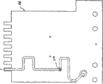
Fig. 6 is the plane graph of flexible print circuit, shows regional A-F;
Fig. 6 a is the detail drawing of the regional A of Fig. 6 flexible print circuit;
Fig. 6 b is the detail drawing of the regional B of Fig. 6 flexible print circuit;
Fig. 6 c is the detail drawing of the regional C of Fig. 6 flexible print circuit;
Fig. 6 d is the detail drawing of the regional D of Fig. 6 flexible print circuit;
Fig. 6 e is the detail drawing of the regional E of Fig. 6 flexible print circuit;
Fig. 6 f is the detail drawing of the regional F of Fig. 6 flexible print circuit;
Fig. 6 g is the plane graph with Fig. 6 flexible print circuit of hatching;
Fig. 6 h is the plane graph of Fig. 6 flexible print circuit, shows the conductive traces that is associated with the first conductor;
Fig. 6 i is the plane graph of Fig. 6 flexible print circuit, shows the conductive traces that is associated with the second conductor;
Fig. 6 j is the plane graph of Fig. 6 flexible print circuit, shows the conductive traces that is associated with the 3rd conductor;
Fig. 6 k is the plane graph of Fig. 6 flexible print circuit, shows the conductive traces that is associated with the 4th conductor;
Fig. 6 l is the plane graph of Fig. 6 flexible print circuit, shows the conductive traces that is associated with the 5th conductor;
Fig. 6 m is the plane graph of Fig. 6 flexible print circuit, shows the conductive traces that is associated with the 6th conductor;
Fig. 6 n is the plane graph of Fig. 6 flexible print circuit, shows the conductive traces that is associated with the 7th conductor;
Fig. 6 o is the plane graph of Fig. 6 flexible print circuit, shows the conductive traces that is associated with the 8th conductor;
Fig. 7 is the cross-sectional view that Fig. 6 flexible print circuit is obtained along A-A line in Fig. 6 g;
Fig. 8 a is the cross-sectional view that Fig. 6 flexible print circuit is obtained along B-B line in 6g;
Fig. 8 b is the cross-sectional view that Fig. 6 flexible print circuit is obtained along C-C line in 6g;
Fig. 9 is the cross-sectional view that Fig. 6 flexible print circuit is obtained along D-D line in 6g;
Figure 10 a is the cross-sectional view that Fig. 6 flexible print circuit is obtained along E-E line in 6g;
Figure 10 b is the cross-sectional view that Fig. 6 flexible print circuit is obtained along F-F line in 6g;
Figure 11 is the cross-sectional view that Fig. 6 flexible print circuit is obtained along G-G line in 6g;
Figure 12 is the cross-sectional view that Fig. 6 flexible print circuit is obtained along H-H line in 6g;
Figure 13 is the cross-sectional view that Fig. 6 flexible print circuit is obtained along I-I line in 6g;
Figure 14 is the detail drawing of details J in Fig. 6 g;
Figure 15 is the detail drawing of details K in Fig. 6 g;
Figure 16 is the detail drawing of details L in Fig. 6 g;
Figure 17 is the detail drawing of details M in Fig. 6 g;
Figure 18 is the side sectional view of electrical socket according to another embodiment of the present invention;
Figure 19 is the exploded view of Figure 18 electrical socket;
Figure 20 is the detail drawing of Figure 19 details N;
Figure 21 is the stereogram of the contact-casing assembly of Figure 18 electrical socket;
Figure 21 a is the stereogram of another embodiment of the contact-casing assembly of Figure 18 electrical socket;
Figure 22 is the stereogram of the contact-casing assembly of Figure 18 electrical socket;
Figure 23 is the stereogram of IDC and associated stems according to an embodiment of the invention;
Figure 24 is the vertical view of Figure 23 IDC;
Figure 25 is the front view of Figure 23 IDC;
Figure 26 is the rearview of Figure 23 IDC;
Figure 27 is the end view of Figure 23 IDC;
Figure 28 is the detail drawing of Figure 27 details O;
Figure 29 is the detail drawing of Figure 27 details P;
Figure 30 is the cross-sectional view of obtaining along Q-Q line in Figure 27;
Figure 31 is the plane graph of another FPC 200 that can use together with the socket shown in Figure 33-45;
Figure 32 is the stereogram of variable capacitance 250 shown in Figure 31;
Figure 33 is the side sectional view of socket front portion, shows the contact 1 or 8 of comb position;
Figure 34 is the side sectional view of socket front portion, shows the contact 1 or 8 of solid-state insertion position;
Figure 35 is the side sectional view of socket front portion, shows in the contact 2,4,5 or 7 that the comb position is arranged;
Figure 36 is the upper right side front exploded view of socket according to an embodiment of the invention;
Figure 37 is the close up view that the details of the front sled with the contact that comprises spring contact is shown;
Figure 38 is the close up view that the details of rear contact guides is shown;
Figure 39 is the lower left rear exploded perspective view of socket according to an embodiment of the invention;
Figure 40 is the close up view that the bottom detail of the front sled with the contact that comprises spring contact is shown;
Figure 41 is the first rear perspective view of jack housing according to an embodiment of the invention;
Figure 42 is the second rear perspective view of jack housing according to an embodiment of the invention;
Figure 43 is the stereogram that comprises the contact of spring contact;
Figure 44 is the stereogram of long contact; And
Figure 45 is the stereogram of short contact.
Embodiment
The present invention relates to be used to reducing the method and apparatus of crosstalk in electrical connectors.The present invention has utilized the principle of crosstalking that subtracts of the U.S. Patent No. 5,997,358 of authorizing the people such as Adriaenssens, and this patent all is incorporated into this by reference.the application is further by reference all in conjunction with following application: the commonly assigned U.S. Provisional Patent Application No.60/544 that is entitled as " method and apparatus that reduces crosstalk in electrical connectors " (" Method and Apparatus for Reducing Crosstalk in Electrical Connectors ") that on February 12nd, 2004 submitted to, 050, and the commonly assigned U.S. Provisional Patent Application No.11/055 that is entitled as " method and apparatus that reduces crosstalk in electrical connectors " (" Method and Apparatus for Reducing Crosstalk in Electrical Connectors ") of submission on February 10th, 2005, 344.
Referring now to Fig. 1,, show the exploded view of electrical socket 10.Contact 12 is applicable to carry out physics and electrically contact with plug contacts (not shown in Figure 1), and further with flexible print circuit (FPC) 14, electrically contacts.These contacts 12 are by mechanical erection in contact sled 16, and contact-sled assembly is suitable for inserting in baseplug shell 18.
In the embodiment show in figure 1, FPC 14 has the rigid extensions 20 for housing insulation displacement connector (IDC) 22.According to one embodiment of present invention, this rigid extensions 20 is necessary ends of FPC.This IDC 22 stretches out back shell 24, and carries out physics and electrically contact with conductor 26.In the embodiment in figure 1, eight conductors 26 are configured to four pairs.End cap 28 has encapsulated the connection of 26 of IDC22 and conductors.The terminal of other pattern also can be used in the present invention, as downward punching pattern terminal.
Referring now to Fig. 2,, the exploded view of contact assembly shows between contact 12 and FPC 14 connection at socket contact 30 places of FPC14.The machinery of FPC 14 and contact 12 and be electrically connected to be positioned at plug/jack interface 31 under.The socket contact 30 of FPC 14 preferably is welded on the contact 12 of plug/jack interface reverse side by the resistance welded of welding rivet.Socket contact 12 is relatively short, and their conducted signal electric currents along its length not.IDC 22 stretches out from the rigid extensions 20 of FPC 14, enters the IDC socket 32 of FPC 14.Fig. 3 is the rear perspective view of Fig. 2 contact assembly, shows the socket contact 30 contact contacts 12 of FPC, and further shows rigid extensions 20 extensions of IDC 22 from FPC 14.
Can be by the distinct methods setting according to FPC of the present invention.For example, Figure 4 and 5 are side sectional views that two kinds of configurations of FPC 14 in electrical socket are shown.In Fig. 4, FPC 14 is placed with the rear portion bending to electrical socket 10 of the socket contact 30 that makes FPC14.This is configuration shown in Figure 1.Fig. 5 shows another kind of configuration, wherein in FPC 14, be provided with frontal arc 34 so that socket contact 30 to the place ahead bending of another electrical socket 36.In Fig. 4 and Fig. 5, the socket contact 30 of FPC 14 contacts under plug/jack interface 31 with socket contact 12.
Referring now to Fig. 6,, show the plane graph of FPC 114 according to an embodiment of the invention.Socket contact 130 comprises for the welding rivet 131 of resistance welded to socket contact.Socket contact 130 from 1 to 8 numbering is with corresponding to eight conductors (being arranged to four pairs), and correspondingly to IDC socket 132 numberings.Conductive traces 138 is set on FPC 114.FPC 114 is applicable to the socket shown in Figure 18-22 " horizontal-extending " embodiment.
Critical matching compensation for as shown in Figure 6 conductor to 3,6 to 4,5.Following region description is relevant to that these are right, and following elaboration about coupling be relevant to these conductors between coupling.Zone A, B, C, D, E and F illustrate with the dotted line frame in Fig. 6, and in regional A-F the conductive traces plane graph respectively shown in Fig. 6 a-6f.
Zone A is from the transitional region that is connected to near-end cross (NEXT) compensatory zone with socket contact 112 (as shown in figure 18).
Zone B is the NEXT compensatory zone.
Zone C is the transitional region from the NEXT compensatory zone to the NEXT crosstalk zone.This regional purpose of design is to make its inductive and the length of capacitive couplings and circuit paths and equating of a-quadrant.
Zone E is the NEXT crosstalk zone.
Zone F is for connecting the neutral region of NEXT crosstalk zone and IDC socket 32.
The size of total crosstalk couplings of NEXT crosstalk zone approximately equates with standard plug.
The twice that the size of total compensation coupling of NEXT compensatory zone is slightly less than the standard plug crosstalk couplings adds the total twice that is coupled of regional A.
All above-mentioned zone A-C, E and F have distributed couplings and without remote couplings.
In the active centre of standard plug coupling and the phase angle variations between NEXT compensatory zone center, approximate the phase angle variations between NEXT crosstalk zone center and NEXT compensatory zone.
Therefore, the combination of socket and standard plug is about the Central Symmetry of NEXT compensatory zone.
Above result is that forward direction NEXT equals reverse NEXT.
Because the NEXT compensatory zone is connected with plug/jack interface by short circuit path in FPC, the variation that the phase angle variations between them is minimized and compensates with frequency is minimized.
The coupling of the total inductance of NEXT compensatory zone approximates the total inductance coupling of balance of the circuit paths of socket and standard plug.Result is very low FEXT.
The flexibility of FPC makes it when plug is installed, not completely unify mobile socket contact with all to be connected.It also is convenient to the different azimuth of IDC or is connected with printed circuit board (PCB) (PCB).The dielectric layer that PCB is thinner of comparing of FPC is convenient to highdensity inductance and capacitive coupling, and this has encouraged relatively short NEXT compensatory zone.
The length of NEXT compensatory zone preferably approximates NEXT crosstalk zone length.Result is that the FPC track width that is tending towards consistent on single FPC changes the approximately identical size of the capacitive coupling of NEXT compensatory zone and NEXT crosstalk zone change.This makes the compensation that changes because of track width change and minimizes.
Zone D is the compensatory zone of compensation socket contact.The long-range capacitive coupling that it provides close plug/jack interface to connect.
As shown in Figure 6 to 1,2 & 7,8 circuit paths illustrates a kind of method that realizes the compensation between these right combinations.The realization comparison 3,6 to 4,5 of these other right required compensation much easier.
Fig. 6 h-6o illustrates respectively the conductive traces that is associated with conductor 1-8, and wherein the track on FPC 114 upper stratas illustrates with solid line and the track of FPC 114 lower floors is shown in broken lines.Through hole 117 is from the upper strata of FPC 114 to the conductive path of lower floor.The length of the conductive traces to 3,6 and 4,5 about equally.
Referring now to Fig. 7,, the cross section of the socket contact 130 of FPC 114 is shown along the cross-sectional view of Fig. 6 g center line A-A.Similarly, Fig. 8 a is the cross-sectional view along Fig. 6 g center line B-B.Fig. 8 b is the cross-sectional view along Fig. 6 g center line C-C.
Fig. 9 is the cross-sectional view along Fig. 6 g center line D-D.
Figure 10 a is the cross-sectional view along Fig. 6 g center line E-E.
Figure 10 b is the cross-sectional view along Fig. 6 g center line F-F.
Figure 11 is the cross-sectional view along Fig. 6 g center line G-G.
Figure 12 is the cross-sectional view along Fig. 6 g center line H-H.
Figure 13 is the cross-sectional view along Fig. 6 g center line I-I.
The label 1-8 that is associated with conductive traces in Fig. 7-13 illustrates the conductive traces the quoted socket contact 130 corresponding to FPC 114, and again corresponding to the respective conductors that is connected with socket.
Figure 14-17 are respectively the detail drawings of details area J, K, L and the M of Fig. 6 g.Size shown in Fig. 6 g and Fig. 7-17 is take inch as unit, and be used to a specific embodiment of the present invention is described.Should be appreciated that, can expect that the embodiment with different size falls within the scope of the invention.
Referring now to Figure 18,, the cross-sectional view of the socket 110 of the horizontal-extending part 120 with FPC 114 is shown.The same with the embodiment of Fig. 1, electric and Mechanical Contact is carried out with FPC 114 in contact 112, and plug-socket interface 131 is placed in directly over this contact between contact 112 and FPC 114.IDC 122 is inserted in the IDC socket of horizontal-extending part 120 of FPC 114.For example the terminal of other pattern of downward punching terminal, also can be used for the present invention.
Figure 19 is the exploded view of socket 110.Socket main shell 118 is applicable to hold the sled 116 with installation contact 112 wherein.IDC block assembly 115 is additional on back shell 124, and end cap 128 is arranged at the rear portion of socket 110.IDC122 is flatly placed to hold in the extension 120 of FPC 114.Figure 20 is the detail drawing of Figure 19 details N, shows the electric and Mechanical Contact of FPC 114 and contact 112, and IDC socket 132 further is shown is suitable for being connected with IDC 122.
Figure 21,21a and 22 are the stereograms that shell 124, IDC block assembly 115, contact 112 are shown and have the FPC 114 of horizontal direction rigid extensions 120.In another embodiment, as shown in Figure 21 a, in IDC block assembly 115, one or more pairs of IDC 122 can be provided with crossover stems 123.
According to one embodiment of present invention, as shown in figure 23, IDC 122 is provided with main line 134, and some of them main line 134 has crosspoint 136.Figure 23 is the stereogram that the IDC 122a-h of the first to the 8th conductor that corresponds respectively to socket is shown.The first to the 8th main line 134a-h is corresponding with first to the 8th IDC 122a-h respectively.The first and second main line 134a and 134b are intersected with each other at the first 136a place, crosspoint, and the 4th and the 5th main line 134d and 134e are intersected with each other at the second 136b place, crosspoint.
Figure 24 is first, second, the vertical view of the 7th and the 8th IDC 122a, 122b, 122g and 122h, shows the first crosspoint 136a in the first and second main line 134a and 134b.
Figure 25 is the front view of IDC 122a-h and associated stems 134a-h thereof, shows the first and second crosspoint 136a and 136b.Figure 26 is the rearview of IDC 122a-h, shows the feature of Figure 25.
Figure 27 is the end view of Figure 23 embodiment, shows IDC and associated stems.Show the first crosspoint 136a between the first and second main line 134a and 134b.Figure 28 is the view of Figure 27 details O, shows the first crosspoint 136a.Figure 29 is the view of Figure 27 details P, shows the 3rd and the 6th main line 134c and 134f.Figure 30 is the cross-sectional view of Figure 27 cross section Q-Q, shows the 3rd, the 4th, the 5th and the 6th IDC 122c-f with its associated stems 134c-f, and the second crosspoint 136b between the 4th and the 5th main line 134d and 134e further is shown.First, second, the cross section of the 7th and the 8th main line 134a, 134b, 134g and 134h is also shown in Figure 30.
Figure 31 is the plane graph of another FPC 200, and this FPC 200 can use together with socket as shown in Figure 33-45.Socket contact 230 comprises for the through hole that is electrically connected to socket contact (plated film through hole) 231.This socket contact 230 is corresponding to eight conductors (being arranged to four pairs).Only have four ( conductors 3,4,5 and 6) shown in Figure 31.Conductive traces 238 is arranged on FPC 200.FPC 200 is applicable to " vertical stretch divides " embodiment of socket shown in Figure 33-45.
Critical matching compensation for as shown in figure 31 conductor to 3,6 to 4,5.Following region description is right about these, and following elaboration about coupling be relevant to these conductors between coupling.Zone A, B, C, D and E are shown in Figure 31.Identify hereinafter these zones, but function is described hereinbefore with reference to Fig. 6-17.
Zone A is from the transitional region that is connected to near-end cross (NEXT) compensatory zone with socket contact.
Zone B is the NEXT compensatory zone.As described in, but it comprises the electric capacity 250 (describing hereinafter with reference to Figure 32) of optional variable.
Zone C is the transitional region from the NEXT compensatory zone to the NEXT crosstalk zone.The purpose of design of one's respective area is to make its inductance and the length of capacitive coupling and circuit paths and equating of a-quadrant.
Zone E is the NEXT crosstalk zone.
In Figure 31, the following track of regional E forms the neutral region that connects NEXT crosstalk zone (regional E) and IDC socket.
Figure 32 is the stereogram of variable capacitance 250 shown in Figure 31.This variable capacitance 250 provides with frequency increases the capacitive coupling that effectively reduces.Figure 32 is the top perspective view that capacitor board is shown of this part, wherein for ease of explanation, has removed substrate.Generally speaking, the distributed couplings of compensatory zone can change with the electric capacity of variable capacitance 250 remote couplings big or small reducing.The sequence number that the variable capacitance coupling technique was submitted on April 6th, 2004 is 60/559,846, be entitled as in the U.S. Patent application of " having through improving the electric connector of crosstalk compensation " (" Electrical Connector with Improved Crosstalk Compensation ") and describe, this application all is incorporated into this by reference.
Figure 33-45th, each view of the present invention's one illustrative embodiment, wherein the alternation length contacts comprises be used to being connected to the Monolithic spring folder of flexible print circuit (FPC).Figure 33-35th, the part side sectional view of this socket, Figure 36 and Figure 39 are the exploded perspective views of whole socket.Figure 37,38 and 40-42 be the detail perspective view of jack assemblies.Figure 43-45 show the details of socket contact (also referred to as plug interface contacts).
Socket 300 comprises shell 302, and it comprises integrated front comb (front comb) 304 and " sandwich " contact holder 306, for supporting and locate a plurality of contacts 308.This front comb 304 limited contact 308 on move.Each contact 308 all has corresponding rear portion contact guide groove 310, and contact 308 can move into this guide groove 310 when the plug (not shown) inserts socket 300.FPC 312 at one end with printed circuit board (PCB) (PCB) 314 electric and mechanical connections, PCB 314 further is connected to the IDC 316 that is connected with the network cable (not shown).The second end of FPC 312 is connected with contact 308 by a plurality of spring contacts 318.Each spring contact 318 is preferably s shape, thereby to support safely FPC 312, the good electrical connection between contact 308 and FPC 312 is maintained.This socket also comprises for front sled (contact 308 is distributed in around it) being arranged on to the bottom fixed board 320 of shell 302.Rear sled 324 is by shell (with the assembly that is loaded on wherein) and line lid 326 mechanical connections, and this line cover is designed to hold the network cable that is placed with many wire (not shown) in IDC 316.Shown in certain line lid 326, strain relief clip 328 is clamped to network cable suitable position safely, thereby reduces the stress on each wire in network cable.The particular arrangement of rear chute 324, line lid 326 and strain relief clip 328 only illustrates as example.Also can use many other designs, comprise the design of those downward punching sockets.
An advantage of the socket 300 of describing with reference to Figure 33-45 is to use the contact 308 with alternation length.As shown in Figure 43-45, half contact 308a is longer than second half 308b on length.The arrangement although the spring contact 318 on each contact 308 is in alignment with each other is in fact alternation around the lower portion of the front sled be used to being fixed to contact holder 306 from the end to end of front sled 322.In this preferred embodiment, middle two contacts 308 are the identical adjacent contacts 308 of only two length.Difference in length between adjacent contacts 308a and 308b causes contact 308a and 308b to be positioned at relative to each other diverse location.Reduced like this contact between capacitive coupling, and capacitive coupling has reduced to crosstalk.For holding different contact 308a and 308b, front comb 304 and front sled 322 are designed to two kinds of length of contact.
Another feature of contact 308 design is that the contact length corresponding with wire 1 and 8 (external contact) is longer.This help to hold 8 pin plugs (wherein contact 1 and 8 and plug in the corresponding contacts electrical connection) and 6 pin plugs (wherein contact 1 and 8 is partly depressed in the shared solid plastics of most of 6 pin plugs).Referring to Figure 34, the contact 1 or 8 while showing 6 pin plugs insertion.
Disclosed invention provides a kind of application to subtract the electric connector of the technology of crosstalking.The embodiment of the present invention and the preferred embodiment that should be noted that above description and explanation are not the exhaustive list that the present invention can take form; And on the contrary as the exemplary and illustrative embodiment of understanding at present of the present invention.And unrestricted, the socket 110 in Figure 18-22 can be manufactured with the frontal arc in FPC 114 as example, is similar to frontal arc shown in Figure 5 34.
Claims (15)
1. crosstalk compensation devices for the modular communication connector, comprise socket and plug, described socket has the socket contact that consists of the metal cantilever beam, described device comprises circuit board, it first end by flexible member with near socket contact machinery relative and socket contact and plug boundary part when installing be electrically connected, described circuit board is at the second end and insulation displacement connector is mechanical and electrical connection, thereby provides network path at least two pairs of conductors between socket contact and insulation displacement connector.
2. crosstalk compensation devices as claimed in claim 1, is characterized in that, described circuit board separates with socket contact at flexible member and socket contact junction.
3. crosstalk compensation devices as claimed in claim 1, is characterized in that, described circuit board is flexible print circuit.
4. crosstalk compensation devices as claimed in claim 3, is characterized in that, described flexible print circuit becomes or invests printed circuit board at its second end.
5. crosstalk compensation devices as claimed in claim 3, it is characterized in that, described network path comprises conductive traces, described conductive traces crosstalk compensation is provided and comprise near-end compensatory zone, near-end cross zone, socket contact with the First Transition between the near-end compensatory zone the second transitional region between regional and near-end compensatory zone and near-end cross zone.
6. crosstalk compensation devices as claimed in claim 5, is characterized in that, in the association size of total crosstalk couplings in the described near-end cross of first frequency zone, approximates total crosstalk couplings of standard plug.
7. crosstalk compensation devices as claimed in claim 6, is characterized in that, the twice that is slightly less than total compensation coupling of standard plug in the size of the total compensation coupling of the described near-end compensatory zone of first frequency adds total compensation coupling of the first and second transitional regions.
8. crosstalk compensation devices as claimed in claim 7, is characterized in that, described near-end compensatory zone, described near-end cross zone and the first and second transitional regions all have distributed couplings separately and there is no remote couplings.
9. crosstalk compensation devices as claimed in claim 8, it is characterized in that, in coupling active centre and first phase angle variations between described near-end compensatory zone center of the standard plug that first frequency is installed, approximate the second phase angle variations between described near-end cross regional center and described near-end compensatory zone center.
10. crosstalk compensation devices as claimed in claim 9, is characterized in that, the forward direction near-end that causes is substantially equal to reverse near-end.
11. crosstalk compensation devices as claimed in claim 5, is characterized in that, the coupling of the total inductance of described near-end compensatory zone approximates the total inductance coupling that standard plug and socket deduct the near-end compensatory zone.
12. crosstalk compensation devices as claimed in claim 11, is characterized in that, thereby cause relatively low far-end cross talk.
13. crosstalk compensation devices as claimed in claim 5, is characterized in that, described near-end compensatory zone approximates the near-end cross zone on length.
14. crosstalk compensation devices as claimed in claim 3, is characterized in that, described socket contact all has associated length and width separately, and described width is less than length, and wherein socket contact can not be along length conducted signal electric current when packing plug into socket.
15. crosstalk compensation devices as claimed in claim 3, is characterized in that, at least two insulation displacement connectors have the main line of intersection.
Applications Claiming Priority (4)
| Application Number | Priority Date | Filing Date | Title |
|---|---|---|---|
| US55299504P | 2004-03-12 | 2004-03-12 | |
| US60/552,995 | 2004-03-12 | ||
| US55865704P | 2004-04-01 | 2004-04-01 | |
| US60/558,657 | 2004-04-01 |
Related Parent Applications (1)
| Application Number | Title | Priority Date | Filing Date |
|---|---|---|---|
| CN2005800078096A Division CN1930746B (en) | 2004-03-12 | 2005-03-11 | Methods and apparatus for reducing crosstalk in electrical connectors |
Publications (2)
| Publication Number | Publication Date |
|---|---|
| CN102082367A CN102082367A (en) | 2011-06-01 |
| CN102082367B true CN102082367B (en) | 2013-11-20 |
Family
ID=34962461
Family Applications (2)
| Application Number | Title | Priority Date | Filing Date |
|---|---|---|---|
| CN2005800078096A Active CN1930746B (en) | 2004-03-12 | 2005-03-11 | Methods and apparatus for reducing crosstalk in electrical connectors |
| CN2010105369067A Active CN102082367B (en) | 2004-03-12 | 2005-03-11 | Methods and apparatus for reducing crosstalk in electrical connectors |
Family Applications Before (1)
| Application Number | Title | Priority Date | Filing Date |
|---|---|---|---|
| CN2005800078096A Active CN1930746B (en) | 2004-03-12 | 2005-03-11 | Methods and apparatus for reducing crosstalk in electrical connectors |
Country Status (5)
| Country | Link |
|---|---|
| US (6) | US7252554B2 (en) |
| EP (1) | EP1723702B1 (en) |
| JP (1) | JP4881291B2 (en) |
| CN (2) | CN1930746B (en) |
| WO (1) | WO2005091444A1 (en) |
Families Citing this family (107)
| Publication number | Priority date | Publication date | Assignee | Title |
|---|---|---|---|---|
| US7265300B2 (en) * | 2003-03-21 | 2007-09-04 | Commscope Solutions Properties, Llc | Next high frequency improvement using hybrid substrates of two materials with different dielectric constant frequency slopes |
| US7182649B2 (en) | 2003-12-22 | 2007-02-27 | Panduit Corp. | Inductive and capacitive coupling balancing electrical connector |
| US7179131B2 (en) | 2004-02-12 | 2007-02-20 | Panduit Corp. | Methods and apparatus for reducing crosstalk in electrical connectors |
| US20170098911A1 (en) * | 2004-03-12 | 2017-04-06 | Panduit Corp. | Method for Reducing Crosstalk in Electrical Connectors |
| WO2005091444A1 (en) * | 2004-03-12 | 2005-09-29 | Panduit Corp. | Methods and apparatus for reducing crosstalk in electrical connectors |
| US7153168B2 (en) * | 2004-04-06 | 2006-12-26 | Panduit Corp. | Electrical connector with improved crosstalk compensation |
| US7980900B2 (en) * | 2004-05-14 | 2011-07-19 | Commscope, Inc. Of North Carolina | Next high frequency improvement by using frequency dependent effective capacitance |
| US7190594B2 (en) * | 2004-05-14 | 2007-03-13 | Commscope Solutions Properties, Llc | Next high frequency improvement by using frequency dependent effective capacitance |
| EP1774625B1 (en) * | 2004-07-13 | 2014-06-25 | Panduit Corporation | Communications connector with flexible printed circuit board |
| US7271985B1 (en) * | 2004-09-24 | 2007-09-18 | Storage Technology Corporation | System and method for crosstalk reduction in a flexible trace interconnect array |
| EP2390967B1 (en) * | 2005-07-15 | 2013-02-13 | Panduit Corporation | Communications connector with crimped contacts |
| US7294024B2 (en) * | 2006-01-06 | 2007-11-13 | Adc Telecommunications, Inc. | Methods and systems for minimizing alien crosstalk between connectors |
| EP1987569A1 (en) * | 2006-02-13 | 2008-11-05 | Panduit Corp. | Connector with crosstalk compensation |
| US7686650B2 (en) * | 2006-05-17 | 2010-03-30 | Bel Fuse Ltd. | High speed modular jack with flexible compensation circuit |
| DE202006009504U1 (en) * | 2006-06-14 | 2006-08-24 | CCS Technology, Inc., Wilmington | Electric plug connector or data socket with a flexible circuit board providing connection between the data plug and the electrical path of the socket |
| JP4915585B2 (en) * | 2006-09-21 | 2012-04-11 | パナソニック株式会社 | Modular plug |
| JP4752699B2 (en) * | 2006-09-21 | 2011-08-17 | パナソニック電工株式会社 | Modular plug |
| WO2008048467A2 (en) | 2006-10-13 | 2008-04-24 | Adc Gmbh | Connecting hardware with multi-stage inductive and capacitive crosstalk compensation |
| WO2008076813A2 (en) | 2006-12-13 | 2008-06-26 | Panduit Corp. | Communication jack having layered plug interface contacts |
| DE102007002769B4 (en) * | 2007-01-18 | 2008-10-16 | Adc Gmbh | Terminal strip |
| DE102007002766B4 (en) * | 2007-01-18 | 2014-05-22 | Tyco Electronics Services Gmbh | Electrical connector |
| DE102007002767B3 (en) * | 2007-01-18 | 2008-08-21 | Adc Gmbh | Electrical connector |
| DE102007002768A1 (en) * | 2007-01-18 | 2008-07-24 | Adc Gmbh | Electrical contact arrangement for telecommunications and data technology |
| DE102007005959A1 (en) * | 2007-02-06 | 2008-08-14 | Adc Gmbh | Connectors |
| US7874878B2 (en) | 2007-03-20 | 2011-01-25 | Panduit Corp. | Plug/jack system having PCB with lattice network |
| US7651369B2 (en) | 2007-03-29 | 2010-01-26 | The Siemon Company | Telecommunications connectors and apparatus for mounting the same |
| US7427218B1 (en) * | 2007-05-23 | 2008-09-23 | Commscope, Inc. Of North Carolina | Communications connectors with staggered contacts that connect to a printed circuit board via contact pads |
| FR2919434B1 (en) * | 2007-07-25 | 2009-10-23 | Legrand France | CONNECTOR FOR COMPUTER NETWORKS. |
| WO2009015487A1 (en) * | 2007-08-01 | 2009-02-05 | Belden Cdt Canada Inc. | Connector with insulation piercing contact |
| US7641521B2 (en) * | 2008-04-15 | 2010-01-05 | Tyco Electronics Corporation | Electrical connector with compensation loops |
| US7976348B2 (en) * | 2008-05-07 | 2011-07-12 | Ortronics, Inc. | Modular insert and jack including moveable reactance section |
| US7601034B1 (en) * | 2008-05-07 | 2009-10-13 | Ortronics, Inc. | Modular insert and jack including moveable reactance section |
| US7874865B2 (en) * | 2008-06-20 | 2011-01-25 | Tyco Electronics Corporation | Electrical connector with a compliant cable strain relief element |
| US7621772B1 (en) * | 2008-06-20 | 2009-11-24 | Tyco Electronics Corporation | Electrical connector with a compliant cable strain relief element |
| US7927153B2 (en) * | 2008-08-13 | 2011-04-19 | Panduit Corp. | Communications connector with multi-stage compensation |
| BRPI0917310A2 (en) * | 2008-08-20 | 2015-11-17 | Panduit Corp | communication jack for use in a communication network |
| US7794286B2 (en) * | 2008-12-12 | 2010-09-14 | Hubbell Incorporated | Electrical connector with separate contact mounting and compensation boards |
| EP2209172A1 (en) * | 2009-01-15 | 2010-07-21 | 3M Innovative Properties Company | Telecommunications Jack with a Multilayer PCB |
| US8047879B2 (en) * | 2009-01-26 | 2011-11-01 | Commscope, Inc. Of North Carolina | Printed wiring boards and communication connectors having series inductor-capacitor crosstalk compensation circuits that share a common inductor |
| EP2256867B1 (en) * | 2009-05-11 | 2017-10-04 | CommScope Connectivity Spain, S.L. | Electrical Connector |
| US8016621B2 (en) | 2009-08-25 | 2011-09-13 | Tyco Electronics Corporation | Electrical connector having an electrically parallel compensation region |
| US8435082B2 (en) | 2010-08-03 | 2013-05-07 | Tyco Electronics Corporation | Electrical connectors and printed circuits having broadside-coupling regions |
| US7967644B2 (en) * | 2009-08-25 | 2011-06-28 | Tyco Electronics Corporation | Electrical connector with separable contacts |
| US7892018B1 (en) | 2009-09-29 | 2011-02-22 | Tyco Electronics Corporation | Electrical connector assembly with two cable loading stop elements |
| US7905744B1 (en) * | 2009-10-20 | 2011-03-15 | John Mezzalingua Associates, Inc. | Cartridge lock registered jack and method of use thereof |
| US8267724B2 (en) * | 2009-11-02 | 2012-09-18 | Fci Americas Technology Llc | Electrical connector having offset mounting terminals |
| US7850492B1 (en) | 2009-11-03 | 2010-12-14 | Panduit Corp. | Communication connector with improved crosstalk compensation |
| EP2403069B1 (en) * | 2010-07-02 | 2017-05-17 | Nexans | Communication assembly comprising a plug connector and a jack assembly provided to be connected |
| CN102270797B (en) * | 2010-06-04 | 2013-12-04 | 富士康(昆山)电脑接插件有限公司 | Module connector and sub circuit board applied in module connector |
| US8638651B2 (en) * | 2011-01-21 | 2014-01-28 | Commscope, Inc. Of North Carolina | Intelligent patching systems and methods using phantom mode control signals and related communications connectors |
| DE102011001225A1 (en) * | 2011-03-11 | 2012-09-13 | Harting Electronics Gmbh & Co. Kg | Connection device and connection method for high-frequency digital signals |
| US8684763B2 (en) | 2011-06-21 | 2014-04-01 | Adc Telecommunications, Inc. | Connector with slideable retention feature and patch cord having the same |
| WO2012177486A2 (en) | 2011-06-21 | 2012-12-27 | Adc Telecommunications, Inc. | Connector with cable retention feature and patch cord having the same |
| EP3470104B1 (en) | 2011-07-13 | 2023-01-25 | Fisher & Paykel Healthcare Limited | Impeller and motor assembly |
| JP5819007B2 (en) | 2011-11-23 | 2015-11-18 | パンドウィット・コーポレーション | Compensation network using orthogonal compensation network |
| US8858266B2 (en) | 2012-02-13 | 2014-10-14 | Sentinel Connector Systems, Inc. | High speed communication jack |
| US9627816B2 (en) | 2012-02-13 | 2017-04-18 | Sentinel Connector System Inc. | High speed grounded communication jack |
| US9653847B2 (en) | 2013-01-11 | 2017-05-16 | Sentinel Connector System, Inc. | High speed communication jack |
| US9337592B2 (en) | 2012-02-13 | 2016-05-10 | Sentinel Connector Systems, Inc. | High speed communication jack |
| US9136647B2 (en) | 2012-06-01 | 2015-09-15 | Panduit Corp. | Communication connector with crosstalk compensation |
| US8790139B2 (en) * | 2012-06-22 | 2014-07-29 | Commscope, Inc. Of North Carolina | Communications jacks having sliding contacts and/or contacts having insulative base members |
| US8961239B2 (en) | 2012-09-07 | 2015-02-24 | Commscope, Inc. Of North Carolina | Communication jack having a plurality of contacts mounted on a flexible printed circuit board |
| TWI493808B (en) * | 2012-11-16 | 2015-07-21 | Frank Ma | Transmission connector |
| US8764476B1 (en) * | 2012-12-06 | 2014-07-01 | Frank Ma | Transmission connector |
| US10471225B2 (en) | 2012-12-18 | 2019-11-12 | Fisher & Paykel Healthcare Limited | Impeller and motor assembly |
| US8915756B2 (en) * | 2013-01-23 | 2014-12-23 | Commscope, Inc. Of North Carolina | Communication connector having a printed circuit board with thin conductive layers |
| US9118134B2 (en) * | 2013-03-01 | 2015-08-25 | Panduit Corp. | RJ-45-compatible communication connector with contacts having wider distal ends |
| US9246463B2 (en) | 2013-03-07 | 2016-01-26 | Panduit Corp. | Compensation networks and communication connectors using said compensation networks |
| US8858268B2 (en) * | 2013-03-14 | 2014-10-14 | Commscope, Inc. Of North Carolina | Communications plugs and patch cords with mode conversion control circuitry |
| US9257792B2 (en) | 2013-03-14 | 2016-02-09 | Panduit Corp. | Connectors and systems having improved crosstalk performance |
| US8858267B2 (en) * | 2013-03-14 | 2014-10-14 | Commscope, Inc. Of North Carolina | Communications plugs and patch cords with mode conversion control circuitry |
| US8894447B2 (en) * | 2013-03-14 | 2014-11-25 | Commscope, Inc. Of North Carolina | Communication plug having a plurality of coupled conductive paths |
| US9088106B2 (en) | 2013-05-14 | 2015-07-21 | Commscope, Inc. Of North Carolina | Communications jacks having flexible printed circuit boards with common mode crosstalk compensation |
| DE102013108131A1 (en) * | 2013-07-30 | 2015-02-05 | MCQ TECH GmbH | Contact set for a connection socket |
| WO2015164538A1 (en) * | 2014-04-23 | 2015-10-29 | Tyco Electronics Corporation | Electrical connector with shield cap and shielded terminals |
| CN105322382B (en) * | 2014-07-31 | 2017-10-31 | 美国莫列斯股份有限公司 | Electrical connector |
| DE102014111049A1 (en) * | 2014-08-04 | 2016-02-04 | Wilhelm Rutenbeck Gmbh & Co. Kg | Socket for telecommunications and / or data transmission systems |
| CN105406232B (en) * | 2014-08-20 | 2018-02-02 | 富士康(昆山)电脑接插件有限公司 | RJ45 socket connectors |
| WO2016033693A1 (en) * | 2014-09-04 | 2016-03-10 | Belden Canada Inc. | Coupler connector and cable terminator with side contacts |
| US9413125B2 (en) | 2014-09-04 | 2016-08-09 | Belden Canada Inc. | Coupler connector and cable terminator with end contacts |
| EP3201995A4 (en) | 2014-10-01 | 2018-06-06 | Sentinel Connector Systems Inc. | High speed communication jack |
| US9966703B2 (en) | 2014-10-17 | 2018-05-08 | Panduit Corp. | Communication connector |
| US9362677B1 (en) * | 2014-12-04 | 2016-06-07 | Adtran Inc. | Crosstalk reducing conductor orientations and methods |
| US10050383B2 (en) | 2015-05-19 | 2018-08-14 | Panduit Corp. | Communication connectors |
| US9912083B2 (en) | 2015-07-21 | 2018-03-06 | Sentinel Connector Systems, Inc. | High speed plug |
| EP3326246B1 (en) | 2015-07-21 | 2022-09-21 | Bel Fuse (Macao Commercial Offshore) Limited | Modular connector plug for high speed data transmission networks |
| US10637196B2 (en) | 2015-11-11 | 2020-04-28 | Bel Fuse (Macao Commercial Offshore) Limited | Modular jack contact assembly having controlled capacitive coupling positioned within a jack housing |
| WO2017083287A1 (en) | 2015-11-11 | 2017-05-18 | Bel Fuse (Macao Commercial Offshore) Limited | Modular jack connector |
| EP3387715B1 (en) | 2015-12-08 | 2021-05-12 | Panduit Corp. | Rj45 shuttered jacks and related communication systems |
| US20170256895A1 (en) * | 2016-03-02 | 2017-09-07 | Panduit Corp. | Communication connector |
| US9985359B2 (en) * | 2016-03-11 | 2018-05-29 | The Siemon Company | Field terminable telecommunications connector |
| US20170317450A1 (en) * | 2016-04-29 | 2017-11-02 | Panduit Corp. | RJ Communication Connectors |
| KR102390264B1 (en) | 2016-05-04 | 2022-04-22 | 센티넬 커넥터 시스템즈, 아이엔씨. | Industrial Large Conductor Plug |
| WO2018067172A1 (en) * | 2016-10-07 | 2018-04-12 | Panduit Corp. | High speed rj45 connector |
| US10734765B2 (en) | 2016-10-31 | 2020-08-04 | Commscope Technologies Llc | Connector with capacitive crosstalk compensation |
| US10361514B2 (en) * | 2017-03-02 | 2019-07-23 | Panduit Corp. | Communication connectors utilizing multiple contact points |
| CN114288513A (en) | 2017-04-23 | 2022-04-08 | 费雪派克医疗保健有限公司 | Breathing assistance apparatus |
| DE102017124594A1 (en) | 2017-10-20 | 2019-04-25 | Harting Electric Gmbh & Co. Kg | Device for electrical contacting |
| US10530106B2 (en) | 2018-01-31 | 2020-01-07 | Bel Fuse (Macao Commercial Offshore) Limited | Modular plug connector with multilayer PCB for very high speed applications |
| US10673184B2 (en) * | 2018-03-27 | 2020-06-02 | Veoneer Us Inc. | Rigid electrical connection to strain sensitive sensing component |
| US11017076B2 (en) | 2018-08-08 | 2021-05-25 | Microsoft Technology Licensing, Llc | Enhancing security using anomaly detection |
| CN111525355A (en) * | 2019-02-01 | 2020-08-11 | 亚旭电脑股份有限公司 | Ethernet transmission line |
| JP2021034161A (en) * | 2019-08-20 | 2021-03-01 | モレックス エルエルシー | Cable assembly and connector assembly |
| TWI743581B (en) * | 2019-10-30 | 2021-10-21 | 好慶科技企業股份有限公司 | Signal communication socket |
| IT202000005407A1 (en) * | 2020-03-13 | 2021-09-13 | Cefla Soc Cooperativa | EQUIPMENT AND METHOD FOR SELECTIVE SORTING OF GROUPS OF PANELS INTENDED FOR DIFFERENT ORDERS |
| US20220311188A1 (en) * | 2021-03-24 | 2022-09-29 | Foxconn (Kunshan) Computer Connector Co., Ltd. | Electrical connector |
| US11787551B1 (en) | 2022-10-06 | 2023-10-17 | Archer Aviation, Inc. | Vertical takeoff and landing aircraft electric engine configuration |
Family Cites Families (80)
| Publication number | Priority date | Publication date | Assignee | Title |
|---|---|---|---|---|
| US5163836A (en) * | 1991-03-11 | 1992-11-17 | Apple Computer, Inc. | Integrated connector module with conductive elastomeric contacts |
| US5186647A (en) * | 1992-02-24 | 1993-02-16 | At&T Bell Laboratories | High frequency electrical connector |
| US5299956B1 (en) * | 1992-03-23 | 1995-10-24 | Superior Modular Prod Inc | Low cross talk electrical connector system |
| US5228872A (en) * | 1992-05-05 | 1993-07-20 | Dan-Chief Enterprise Co., Ltd. | Shielded IDC type modular jack adapter |
| JP3451107B2 (en) * | 1992-10-05 | 2003-09-29 | 株式会社エコ・トゥエンティーワン | Electronic cooling device |
| GB2273397B (en) | 1992-11-16 | 1997-01-29 | Krone Ag | Electrical connectors |
| TW218060B (en) * | 1992-12-23 | 1993-12-21 | Panduit Corp | Communication connector with capacitor label |
| US6464529B1 (en) | 1993-03-12 | 2002-10-15 | Cekan/Cdt A/S | Connector element for high-speed data communications |
| US5503572A (en) * | 1994-05-17 | 1996-04-02 | Mod-Tap Corporation | Communications connectors |
| US5586914A (en) * | 1995-05-19 | 1996-12-24 | The Whitaker Corporation | Electrical connector and an associated method for compensating for crosstalk between a plurality of conductors |
| US5672074A (en) * | 1995-06-22 | 1997-09-30 | Panduit Corp. | Connector mounting receptacles |
| US5769647A (en) * | 1995-11-22 | 1998-06-23 | The Siemon Company | Modular outlet employing a door assembly |
| US5791943A (en) * | 1995-11-22 | 1998-08-11 | The Siemon Company | Reduced crosstalk modular outlet |
| US5716237A (en) * | 1996-06-21 | 1998-02-10 | Lucent Technologies Inc. | Electrical connector with crosstalk compensation |
| US5779503A (en) * | 1996-12-18 | 1998-07-14 | Nordx/Cdt, Inc. | High frequency connector with noise cancelling characteristics |
| US5797764A (en) * | 1997-02-12 | 1998-08-25 | Homaco, Inc. | Low return loss and low crosstalk telecommunications electric circuit |
| DE19708798A1 (en) * | 1997-03-05 | 1998-09-24 | Krone Ag | Arrangement of contact pairs to compensate for the near crosstalk |
| US5915989A (en) * | 1997-05-19 | 1999-06-29 | Lucent Technologies Inc. | Connector with counter-balanced crosswalk compensation scheme |
| US5997358A (en) * | 1997-09-02 | 1999-12-07 | Lucent Technologies Inc. | Electrical connector having time-delayed signal compensation |
| FR2768862B1 (en) * | 1997-09-22 | 1999-12-24 | Infra Sa | LOW POWER SOCKET WITH ORGANIZER REAR CAP |
| EP1036427A1 (en) | 1997-12-05 | 2000-09-20 | Lk A/S | A method of reducing high frequency coupling between pairs of conductors in a connector, and a connector for transferring differential signals |
| US5885111A (en) * | 1998-01-13 | 1999-03-23 | Shiunn Yang Enterprise Co., Ltd. | Keystone jack for digital communication networks |
| JPH11219761A (en) * | 1998-01-30 | 1999-08-10 | Matsushita Electric Works Ltd | Modular plug |
| AUPP224298A0 (en) | 1998-03-06 | 1998-04-02 | Power And Digital Instruments Pty. Ltd. | Improved manner of electrical connection |
| JP2003522368A (en) * | 1998-04-16 | 2003-07-22 | トーマス アンド ベッツ インターナショナル,インク. | Crosstalk reducing electrical jack and plug connector |
| DE19822630C1 (en) * | 1998-05-20 | 2000-09-07 | Krone Gmbh | Arrangement of contact pairs to compensate for the near crosstalk for an electrical connector |
| US6057743A (en) * | 1998-06-22 | 2000-05-02 | Hubbell Incorporation | Distributed noise reduction circuits in telecommunication system connector |
| US6371793B1 (en) * | 1998-08-24 | 2002-04-16 | Panduit Corp. | Low crosstalk modular communication connector |
| US6356162B1 (en) * | 1999-04-02 | 2002-03-12 | Nordx/Cdt, Inc. | Impedance compensation for a cable and connector |
| US6255593B1 (en) * | 1998-09-29 | 2001-07-03 | Nordx/Cdt, Inc. | Method and apparatus for adjusting the coupling reactances between twisted pairs for achieving a desired level of crosstalk |
| US6554638B1 (en) * | 1998-10-14 | 2003-04-29 | Stewart Connector Systems, Inc. | Modular electrical connector assemblies with magnetic filter and/or visual indicator |
| US6379175B1 (en) * | 1998-10-29 | 2002-04-30 | Nordx/Cdt. Inc. | Fixture for controlling the trajectory of wires to reduce crosstalk |
| GB2343558B (en) * | 1998-11-04 | 2002-10-30 | Itt Mfg Enterprises Inc | Electrical connector |
| US6409547B1 (en) | 1998-12-02 | 2002-06-25 | Nordx/Cdt, Inc. | Modular connectors with compensation structures |
| US6155881A (en) * | 1999-02-02 | 2000-12-05 | Lucent Technologies Inc. | Electrical connector with signal compensation |
| FR2791185B1 (en) * | 1999-03-16 | 2001-06-01 | Infra Sa | LOW VOLTAGE CONNECTOR PROVIDED WITH AN ADAPTER AND ADAPTER FOR SUCH A CONNECTOR |
| FR2791816B1 (en) * | 1999-04-01 | 2001-06-15 | Infra Sa | LOW VOLTAGE MALE CONNECTOR |
| US6079996A (en) * | 1999-04-15 | 2000-06-27 | Lucent Technologies Inc. | Selectable compatibility electrical connector jack |
| IL129883A0 (en) * | 1999-05-10 | 2000-02-29 | Rit Techn Ltd | Cable organizer |
| US6168474B1 (en) * | 1999-06-04 | 2001-01-02 | Lucent Technologies Inc. | Communications connector having crosstalk compensation |
| US6176742B1 (en) | 1999-06-25 | 2001-01-23 | Avaya Inc. | Capacitive crosstalk compensation arrangement for communication connectors |
| US6109950A (en) * | 1999-07-12 | 2000-08-29 | Hon Hai Precision Ind. Co., Ltd. | IDC connector having a terminator |
| US6089923A (en) * | 1999-08-20 | 2000-07-18 | Adc Telecommunications, Inc. | Jack including crosstalk compensation for printed circuit board |
| US6196880B1 (en) * | 1999-09-21 | 2001-03-06 | Avaya Technology Corp. | Communication connector assembly with crosstalk compensation |
| ATE295009T1 (en) * | 1999-10-29 | 2005-05-15 | Nexans | MODULAR TELECOMMUNICATIONS CONNECTOR WITH CROSSTALK REDUCTION |
| AU2001229420A1 (en) * | 2000-01-14 | 2001-07-24 | Panduit Corp. | Low crosstalk modular communication connector |
| JP4455711B2 (en) * | 2000-02-15 | 2010-04-21 | ヒロセ電機株式会社 | Modular jack connector |
| US6533618B1 (en) * | 2000-03-31 | 2003-03-18 | Ortronics, Inc. | Bi-directional balance low noise communication interface |
| JP3775163B2 (en) * | 2000-03-31 | 2006-05-17 | 松下電工株式会社 | Modular connector |
| AU2001251547A1 (en) | 2000-04-14 | 2001-10-30 | Tyco Electronics Corporation | Electrical connector for reducing crosstalk |
| US6402560B1 (en) * | 2000-05-31 | 2002-06-11 | Avaya Technology Corp. | Communication connector with crosstalk compensation |
| ATE304264T1 (en) * | 2000-06-14 | 2005-09-15 | Rambus Inc | METHOD AND DEVICE FOR DATA TRANSMISSION WITH REDUCED INTERFERENCE COUPLING |
| DE10051097C2 (en) * | 2000-08-17 | 2002-11-28 | Krone Gmbh | Electrical connector |
| US6379157B1 (en) * | 2000-08-18 | 2002-04-30 | Leviton Manufacturing Co., Inc. | Communication connector with inductive compensation |
| US6350158B1 (en) | 2000-09-19 | 2002-02-26 | Avaya Technology Corp. | Low crosstalk communication connector |
| US6802743B2 (en) * | 2000-09-29 | 2004-10-12 | Ortronics, Inc. | Low noise communication modular connector insert |
| EP1371115A2 (en) * | 2001-03-12 | 2003-12-17 | Nordx/Cdt., Inc. | Electrostatic discharge protected jack |
| FR2823606A1 (en) | 2001-04-17 | 2002-10-18 | Infra Sa | Low voltage female connector having holder receiving male connector and first circuit board contact pins/contact zone connected/second printed circuit board shorter path contact zone connected. |
| US6464541B1 (en) * | 2001-05-23 | 2002-10-15 | Avaya Technology Corp. | Simultaneous near-end and far-end crosstalk compensation in a communication connector |
| US6600865B2 (en) * | 2001-06-21 | 2003-07-29 | Hon Hai Precision Ind. Co., Ltd. | Stacked GBIC guide rail assembly |
| IL145103A (en) * | 2001-08-23 | 2010-05-17 | Rit Techn Ltd | High data rate interconnecting device |
| TW507971U (en) | 2001-09-13 | 2002-10-21 | Perfect Three Mfg Corp | Information connector with distribution terminal panel |
| GB2380334A (en) | 2001-09-28 | 2003-04-02 | Itt Mfg Enterprises Inc | Communication connector having crosstalk compensating means |
| US6881096B2 (en) | 2002-04-15 | 2005-04-19 | Lantronix, Inc. | Compact serial-to-ethernet conversion port |
| JP4061123B2 (en) * | 2002-05-21 | 2008-03-12 | 日立電線株式会社 | Modular jack connector |
| FR2841394B1 (en) | 2002-06-24 | 2004-11-19 | Framatome Connectors Int | CONNECTION DEVICE FOR FLEXIBLE CIRCUIT |
| US6736681B2 (en) * | 2002-10-03 | 2004-05-18 | Avaya Technology Corp. | Communications connector that operates in multiple modes for handling multiple signal types |
| US6814624B2 (en) * | 2002-11-22 | 2004-11-09 | Adc Telecommunications, Inc. | Telecommunications jack assembly |
| DE10310434A1 (en) * | 2003-03-11 | 2004-09-30 | Krone Gmbh | Method for RF tuning of an electrical arrangement and a circuit board suitable for this |
| US7265300B2 (en) * | 2003-03-21 | 2007-09-04 | Commscope Solutions Properties, Llc | Next high frequency improvement using hybrid substrates of two materials with different dielectric constant frequency slopes |
| US7181649B2 (en) | 2003-05-09 | 2007-02-20 | Stmicroelectronics, Inc. | Universal serial bus (USB) smart card having enhanced testing features and related system, integrated circuit, and methods |
| US6769937B1 (en) * | 2003-05-13 | 2004-08-03 | Molex Incorporated | Modular jack assembly for jack plugs with varying numbers of wires |
| US7150657B2 (en) * | 2003-05-23 | 2006-12-19 | Nordx/Cdt Inc. | Wire lead guide and method for terminating a communications cable |
| US7182649B2 (en) | 2003-12-22 | 2007-02-27 | Panduit Corp. | Inductive and capacitive coupling balancing electrical connector |
| US7179131B2 (en) | 2004-02-12 | 2007-02-20 | Panduit Corp. | Methods and apparatus for reducing crosstalk in electrical connectors |
| US7187766B2 (en) * | 2004-02-20 | 2007-03-06 | Adc Incorporated | Methods and systems for compensating for alien crosstalk between connectors |
| WO2005091444A1 (en) * | 2004-03-12 | 2005-09-29 | Panduit Corp. | Methods and apparatus for reducing crosstalk in electrical connectors |
| CA2464834A1 (en) | 2004-04-19 | 2005-10-19 | Nordx/Cdt Inc. | Connector |
| EP1774625B1 (en) * | 2004-07-13 | 2014-06-25 | Panduit Corporation | Communications connector with flexible printed circuit board |
| WO2008076813A2 (en) * | 2006-12-13 | 2008-06-26 | Panduit Corp. | Communication jack having layered plug interface contacts |
-
2005
- 2005-03-11 WO PCT/US2005/008232 patent/WO2005091444A1/en active Application Filing
- 2005-03-11 JP JP2007503061A patent/JP4881291B2/en active Active
- 2005-03-11 CN CN2005800078096A patent/CN1930746B/en active Active
- 2005-03-11 US US11/078,816 patent/US7252554B2/en active Active
- 2005-03-11 CN CN2010105369067A patent/CN102082367B/en active Active
- 2005-03-11 EP EP05725422.9A patent/EP1723702B1/en active Active
-
2007
- 2007-08-03 US US11/833,686 patent/US7823281B2/en not_active Expired - Fee Related
-
2010
- 2010-11-01 US US12/916,687 patent/US8826532B2/en active Active
-
2014
- 2014-09-02 US US14/474,479 patent/US9407044B2/en active Active
-
2016
- 2016-07-27 US US15/220,789 patent/US9722370B2/en active Active
-
2017
- 2017-07-21 US US15/656,443 patent/US9991653B2/en active Active
Also Published As
| Publication number | Publication date |
|---|---|
| US20170324198A1 (en) | 2017-11-09 |
| CN1930746A (en) | 2007-03-14 |
| US9722370B2 (en) | 2017-08-01 |
| JP4881291B2 (en) | 2012-02-22 |
| WO2005091444A1 (en) | 2005-09-29 |
| US9991653B2 (en) | 2018-06-05 |
| CN102082367A (en) | 2011-06-01 |
| EP1723702B1 (en) | 2015-10-28 |
| US20080020652A1 (en) | 2008-01-24 |
| US8826532B2 (en) | 2014-09-09 |
| US7823281B2 (en) | 2010-11-02 |
| US9407044B2 (en) | 2016-08-02 |
| CN1930746B (en) | 2010-12-22 |
| US20160336700A1 (en) | 2016-11-17 |
| US20050202697A1 (en) | 2005-09-15 |
| US7252554B2 (en) | 2007-08-07 |
| US20150024613A1 (en) | 2015-01-22 |
| JP2007529098A (en) | 2007-10-18 |
| EP1723702A1 (en) | 2006-11-22 |
| US20110041331A1 (en) | 2011-02-24 |
Similar Documents
| Publication | Publication Date | Title |
|---|---|---|
| CN102082367B (en) | Methods and apparatus for reducing crosstalk in electrical connectors | |
| EP1435679B1 (en) | Electronic connector and method of performing electronic connection | |
| EP1230714B1 (en) | Low crosstalk modular communication connector | |
| EP2815466B1 (en) | Small form-factor rj-45 plugs with low-profile surface mounted printed circuit board plug blades | |
| US5431584A (en) | Electrical connector with reduced crosstalk | |
| US8353723B2 (en) | Communications patching devices having capacitor-based multi-stage near-end alien crosstalk compensation circuits between adjacent connector ports | |
| US20070190863A1 (en) | Connector with crosstalk compensation | |
| GB2273397A (en) | Electrical connectors | |
| CN201608967U (en) | Crosstalk compensation component, printed circuit board, module jack and socket terminals | |
| US10193242B2 (en) | Printed circuit board based communications plugs that are suitable for field termination and patch cords including such plugs | |
| JP4879694B2 (en) | Electrical connector jack | |
| US6816025B2 (en) | Cross talk compensation circuit | |
| US9819131B2 (en) | RJ-45 communication plug with plug blades received in apertures in a front edge of a printed circuit board | |
| US20170098911A1 (en) | Method for Reducing Crosstalk in Electrical Connectors | |
| US9281622B2 (en) | Communications jacks having low-coupling contacts |
Legal Events
| Date | Code | Title | Description |
|---|---|---|---|
| C06 | Publication | ||
| PB01 | Publication | ||
| C10 | Entry into substantive examination | ||
| SE01 | Entry into force of request for substantive examination | ||
| C14 | Grant of patent or utility model | ||
| GR01 | Patent grant |