EP1128472A1 - Shield connector - Google Patents
Shield connector Download PDFInfo
- Publication number
- EP1128472A1 EP1128472A1 EP00122154A EP00122154A EP1128472A1 EP 1128472 A1 EP1128472 A1 EP 1128472A1 EP 00122154 A EP00122154 A EP 00122154A EP 00122154 A EP00122154 A EP 00122154A EP 1128472 A1 EP1128472 A1 EP 1128472A1
- Authority
- EP
- European Patent Office
- Prior art keywords
- shielding
- shield connector
- electrically conductive
- shielding layer
- flange
- Prior art date
- Legal status (The legal status is an assumption and is not a legal conclusion. Google has not performed a legal analysis and makes no representation as to the accuracy of the status listed.)
- Granted
Links
Images


Classifications
-
- H—ELECTRICITY
- H01—ELECTRIC ELEMENTS
- H01R—ELECTRICALLY-CONDUCTIVE CONNECTIONS; STRUCTURAL ASSOCIATIONS OF A PLURALITY OF MUTUALLY-INSULATED ELECTRICAL CONNECTING ELEMENTS; COUPLING DEVICES; CURRENT COLLECTORS
- H01R9/00—Structural associations of a plurality of mutually-insulated electrical connecting elements, e.g. terminal strips or terminal blocks; Terminals or binding posts mounted upon a base or in a case; Bases therefor
- H01R9/03—Connectors arranged to contact a plurality of the conductors of a multiconductor cable, e.g. tapping connections
- H01R9/05—Connectors arranged to contact a plurality of the conductors of a multiconductor cable, e.g. tapping connections for coaxial cables
- H01R9/0518—Connection to outer conductor by crimping or by crimping ferrule
Definitions
- the present invention relates to a shield connector.
- Figs. 19 and 20 shows a shield connector disclosed in the Unexamined Japanese Patent Application Publication No. Hei 11-26093 as an example of a conventional shield connector.
- This shield connector is comprised of a rubber ring 2, a retaining ring 3, an electrically conductive sleeve 4, and a presser ring 35 which are provided in a tubular resin housing 1, and these members are fitted over a shielding wire 10 and are attached.
- a conductive contact piece 6 is disposed on an outer peripheral surface of a front end of the resin housing 1, and is conductingly connected to a shielding layer 13 of the shielding wire 10 through the electrically conductive sleeve 4.
- the conducting contact piece 6 is conductingly connected to an inner peripheral surface of the attaching hole, thereby allowing the shielding wall and the shielding layer to be conductingly connected to each other.
- the present invention has been devised in view of the above-described circumstances, and its object is to provide a shield connector having a small number of parts.
- the shield connector in accordance with the invention according to aspect 1 is a shield connector which covers a shielding layer exposed at a terminal portion of a shielding wire and is fixed to the shielding wire, and which is attached to a mating shielding wall to conductingly connect the sealing layer and the mating shielding wall, characterized by comprising: an electrically conductive flange having electrical conductivity and adapted to abut against the mating shielding wall; en electrically conductive tubular portion provided in a state of being electrically conducting with the electrically conductive flange and fitted to an inner side or an outer side of the exposed shielding layer so as to be conductingly connected to the shielding layer; and a housing fixed to the shielding wire to hold the electrically conductive flange.
- the flange which is fixed to the mating shielding wall is made electrically conductive, and the shielding layer is conductingly connected to this electrically conductive flange through the electrically conductive tubular portion, whereby the structure for allowing the shielding layer and the mating shielding wall to electrically conduct with each other can be simplified, and the number of parts can be reduced.
- the shield connector according to aspect 1 further comprises an auxiliary sleeve fitted to the electrically conductive tubular portion with the shielding layer placed therebetween.
- the shielding layer is clamped between the electrically conductive tubular portion and the auxiliary sleeve, thereby allowing the shielding layer to be conductingly connected to the electrically conductive tubular portion reliably.
- the shield connector according to aspect 1 is characterized in that the electrically conductive tubular portion and the shielding layer are fused to each other, thereby allowing the shielding layer to be conductingly connected to the electrically conductive tubular portion reliably.
- the shield connector according to any one of aspects 1 to 3 is characterized in that the housing is molded by charging a molten resin into a mold for resin molding in a state in which the shielding wire is placed inside the mold.
- the shield connector according to aspect 4 is characterized in that a waterproofing tubular portion in which a synthetic resin softer than the housing is molded on an outer peripheral surface of the shielding wire prior to molding the housing is provided on an inner side of a rear end portion of the housing.
- the waterproofing tubular portion which is softer than the housing is brought into close contact with the housing and the shielding wire, so that the rear end portion of the housing is provided with waterproof processing.
- the shield connector according to aspect 4 or 5 is characterized in that a resin flowing-in hole for allowing a molten resin to pass therethrough is penetratingly formed in the electrically conductive flange.
- the molten resin if the molten resin is charged into the mold for resin molding in the state in which the shielding wire with the electrically conductve flange attached thereto is placed inside the mold, the molten resin passes through the resin flowing-in hole formed in the electrically conductive flange, thereby allowing the front side and the rear side of the housing with the electrically conductive flange placed therebetween to be molded at one time.
- the shield connector in accordance with the invention according to aspect 7 is a shield connector which covers a shielding layer exposed at a terminal portion of a shielding wire and is fixed to the shielding wire, and which is attached to a mating shielding wall to conductingly connect the sealing layer and the mating shielding wall, characterized by comprising: an electrically conductive flange having electrical conductivity and adapted to abut against the mating shielding wall; a U-shaped slot portion formed in the electrically conductive flange and adapted to accommodate an exposed portion of the shielding layer of the shielding wire and to be conductingly connected to the shielding layer; and a housing molded by disposing the shielding wire together with the electrically conductive flange in a mold for resin molding and by charging a resin into the mold.
- the flange is pressed against the shielding wire from a lateral direction, and the shielding layer of the shielding wire is brought into close contact with the inner surface of the U-shaped slot portion formed in the flange, thereby conductingly connecting the shielding layer and the flange. Then, this subassembly is inserted in a mold to mold the housing.
- the flange which is fixed to the mating shielding wall is made electrically conductive, and the shielding layer is conductingly connected to this electrically conducting flange, so that the structure for allowing the shielding layer and the mating shielding wall to conduct with each other can be simplified, and the number of parts can be reduced.
- the electrically conductive flange is attached from the lateral direction of the shielding wire, the attaching operation is facilitated as compared with an arrangement in which the electrically conductive flange is attached along the axial direction of the shielding wire.
- the inner sleeve is fitted on an inner side of the shielding layer, and the shielding layer is clamped by the inner sleeve and the inner surface of the U-shaped slot portion, thereby allowing the shielding layer to be conductingly connected to the electrically conductive flange reliably.
- the shield connector according to aspect 7 is characterized by further comprising an auxiliary barrel extending along the shielding wire and having at one end thereof a crimping portion for the shielding layer and at another end thereof a U-shaped curved portion for being brought into close contact with an inner surface of the U-shaped slot portion.
- the crimping portion provided at one end of the auxiliary barrel is crimped against the shielding layer of the shielding wire, and the U-shaped curved portion provided at the other end thereof is pressed into the U-shaped slot portion formed in the electrically conductive flange, thereby allowing the electrically conductive flange to be conductingly connected to the shielding layer reliably through the auxiliary barrel.
- the shield connector according to aspect any one of aspects 7 to 9 is characterized in that a waterproof tubular portion in which a synthetic resin softer than the housing is molded on an outer peripheral surface of the shielding wire prior to molding the housing is provided on an inner side of a rear end portion of the housing.
- the waterproof tubular portion softer than the housing is brought into close contact with the housing and the shielding wire, so that the waterproof processing of the rear end portion of the housing is provided.
- a shielding wire 10 has a core wire 11, an inner insulating layer 12, a shielding layer 13, and an outer cladding 14 in that order from the axial side, and at a terminal portion of the shielding wire 10 the core wire 11, the inner insulating layer 12, and the shielding layer 13 are consecutively exposed from the tip side.
- a shield connector in this embodiment is integrally attached to the terminal portion of the shielding wire 10.
- the shield connector has a housing 21 made of a synthetic resin (e.g., polyamide) for covering the shielding layer 13 exposed at the terminal portion of the shielding wire 10.
- the housing 21 has a metallic electrically conductive flange 22 (hereafter simply referred to as the "flange 22”) jutting out laterally from its forwardly offset position.
- the flange 22 has a structure in which after a metallic plate is blanked into, for instance, a pear shape, a bolt inserting hole 23 is formed at a position close to one end (upper end in Fig. 1), a wire inserting hole 24 is formed at a position close to the other end, and four resin flowing-in holes 25 are formed at positions obtained by dividing a peripheral portion of the wirew inserting hole 24 into four equal parts.
- a metallic electrically conductive sleeve 26 (corresponding to an "electrically conductive tubular portion” in the invention) is press-fitted in the wire inserting hole 24, and this electrically conductive sleeve 26 is inserted between the shielding layer 13 and the internal insulating layer 12 in the shielding wire 10.
- a metallic auxiliary sleeve 27 is fitted over the outer side of the shielding layer 13. More specifically, the auxiliary sleeve 27 is formed of a metal, and a hollow cylindrical portion 27A provided at one end thereof is fitted over the outer cladding 14 of the shielding wire 10, while a hexagonal tubular portion 27B provided at the other end thereof is fitted over an exposed portion of the shielding layer 13.
- a front side (see Fig. 2) of the housing 21 located forwardly of the flange 22 forms an inserting portion 28 for insertion into an attaching hole W1 formed in a mating wall W, and an O-ring 29 is fitted in an annular groove 28A formed in its outer peripheral surface.
- a waterproof tubular portion 30 formed of a synthetic resin (e.g., urethane) softer than the housing 21 is provided on the inner peripheral side of a rear end portion of the housing 21.
- a plurality of annular recesses 30A and annular projections 30B are alternately formed on an outer peripheral surface of the waterproof tubular portion 30 along the axial direction.
- the auxiliary sleeve 27 is fitted over the shielding wire 10
- the hhh 27A of the auxiliary sleeve 27 is fitted over an end portion of the outer cladding 14, and the hexagonal tubular portion 27B is fitted over the shielding layer 13.
- the electrically conductive sleeve 26 press-fitted into the flange 22 is fitted over the shielding wire 10 starting from its tip side and is inserted into the inner side of the shielding layer 13. Then, as shown in Fig.
- the upper and lower sides of the hexagonal tubular portion 27B are crimped in such a manner as to be crushed toward the inner side. Consequently, the shielding layer 13 is clamped between the auxiliary sleeve 27 and the electrically conductive sleeve 26 and is conductingly connected to them, thereby allowing the shielding layer 13 to be conductingly connected to the flange 22 through the electrically conductive sleeve 26.
- This shielding wire 10 with the conductive flange 22 and the like attached thereto is set in a mold for a soft resin. Then, a resin (e.g., urethane) in a molten state is charged into the mold to form the waterproof tubular portion 30. Then, this waterproof tubular portion 30 is removed from the mold, and the shielding wire 10 is set in a mold for a resin of higher rigidity. At this time, as shown in Fig.
- a resin e.g., urethane
- a pair of pins P1 provided in the mold are inserted in the rear end-side recess 30A formed in the outer peripheral surface of the waterproof tubular portion 30, and the positions of the waterproof tubular portion 30 and the flange 22 are fixed with the flange 22 clamped at a mold opening plane PL of the mold. Then, a resin (e.g, polyamide) in a molten state is charged into the mold.
- a resin e.g, polyamide
- the resin located rearwardly of the flange 22 in the resin forming space in the mold, the resin passes through the resin flowing-in holes 25 formed in the flange 22 and spreads to the front side of the flange 22 as well, thereby forming the inserting portion 28 (see Fig. 4B) of the shield connector. Then, this molding is removed from the mold, and the O-ring 29 is fitted to the outer surface of the inserting portion 28, thereby completing the operation of assembling the shield connector and the operation of attaching the shield connector to the wire.
- the shield connector is fixed to the shielding wall W by means of a bolt (not shown) .
- the flange 22 is pressed against the shielding wall W and is conductingly connected thereto, thereby allowing the shielding layer 13 to be conductingly connected to the shielding wall W.
- the O-ring 29 is crushed between the outer peripheral surface of the inserting portion 28 and the inner peripheral surface of the attaching hole W1 to attain waterproofing.
- the waterproof tubular portion 30 formed of a synthetic resin softer than the housing 21 is brought into close contact with the inner peripheral surface of the housing 21 and the outer peripheral surface of the shielding wire 10, thereby preventing the entry of water from the rear end portion of the shield connector into the connector,
- the shield connector of this embodiment since the arrangement provided is such that the flange 22 which is fixed to the mating shielding wall W is made electrically conductive, and the shielding layer 13 of the shielding wire 10 is conductingly connected to the electrically conductive sleeve 26 integrally formed therewith by press-fitting, the structure for electrically conducting the shielding layer 13 and the mating shielding wall W is simplified, so that the number of parts can be reduced. Consequently, the manufacturing process is simplified, therebymaking it possible to hold down the cost. In addition, it becomes possible to make the shield connector compact.
- the abutting surfaces of the flange 22 and the mating shielding wall W form the conductingly connecting surfaces of the shield connector and the mating shielding wall W, so that it is possible to secure a large conducting surface than the conventional shield connector.
- the two members are brought into close contact by being tightened by the bolt, the stability of conduction between the shield connector and the mating shielding wall W increases as compared with the conventional shield connector.
- the auxiliary sleeve 51 in this embodiment has a hollow cylindrical shape, and is fitted over the outer cladding 14 of the shielding wire 10, as shown in Fig. 7A. Then, as shown in Fig. 7B, after the shielding layer 13 is turned back so as to be set in a state of covering the outer side of the auxiliary sleeve 51, if the electrically conductive sleeve 50 is fitted over the shielding wire 10, the electrically conductive sleeve 50 is fitted over the outer side of the shielding layer 13, with the result that the shielding layer 13 is placed between the auxiliary sleeve 51 and the electrically conductive sleeve 50.
- a shield connector 60 in this embodiment three shielding wires 10 are integrally connected by using one housing 61 and one electrically conductive flange 62 (as its material, it is possible to cite copper, copper alloy, iron, stainless steel, and the like). It should be noted that since the shielding wires 10, and the electrically conductive sleeves 26 (corresponding to an "electrically conductive member" in the invention) and the auxiliary sleeves 27 which are used for attachment of the shielding wires 10 to the shield connector 60 are the same as those used in the above-described embodiment, these members will be denoted by the same reference numerals.
- the electrically conductive flange 62 has a plate shape which is elongated in the left and right direction as a whole, three circular wire inserting holes 63 are penetratingly formed at fixed pitches in the left and right direction, and a pair of bolt inserting holes 64 are penetratingly formed at opposite end positions sandwiching these three wire inserting holes 63. Circumferentially divided, arcuate resin flowing-in holes 65 are formed around respective peripheral edge portions of the wire inserting holes 63.
- the circular metallic electrically conductive sleeve 26 is press-fitted in each of the wire inserting holes 63, and each electrically conductive sleeve 26 is inserted between the shielding layer 13 and the inner insulating layer 12 of the shielding wire 10.
- the metallic auxiliary sleeve 27 is fitted over the outer periphery of each shielding layer 13.
- the housing 61 has a transversely elongated oval shape as viewed in the axial direction of the shielding wire 10, and that portion of the housing 61 which juts out toward the front side (the upper right side in Figs. 8 and 9) forwardly of the electrically conductive flange 62 is formed as an oval inserting portion 66 which is inserted into the attaching hole W1 of the mating shielding wall W (not shown in Figs. 8 and 9).
- An O-ring 68 is fitted in a groove 67 formed in an outer periphery of this inserting portion 66.
- An oval waterproofing portion 69 formed of a syntheric resin (e.g., urethane) which is softer than the housing 61 is provided on the inner peripheral side of a rear end portion of the housing 61.
- the auxiliary sleeves 27 are fitted over the respective shielding wires 10, and the electrically conductive sleeves 26 are press-fitted in the respective wire inserting holes 63 (see the shielding wire 10 and the wire inserting hole 63 in the middle in Fig. 9).
- a tip portion of each shielding wire 10 is inserted into the electrically conductive sleeve 26, and the rear end portion of each electrically conductive sleeve 26 is inserted between the shielding layer 13 and the inner insulating layer 12 (see the shielding wire 10 and the wire inserting hole 63 on the right-hand side in Fig.
- each auxiliary sleeve 27 is crimped against the shielding wire 10, thereby allowing the shielding layer 13 and the electrically conductive flange 62 to be conductingly connected to each other through the electrically conductive sleeve 26.
- the subassembly of the electrically conductive flange 62 and th like with the three shielding wires 10 thus attached thereto is set in a mold for a soft resin, and a molten resin is charged into the mold, thereby molding the waterproofing portion 69. Then, the molded piece is removed from the mold, is set in a mold for a resin having higher regidity, and a molten resin (e.g., polyamide) is charged into the mold, thereby molding the housing 61 and the inserting portion 66. After molding, the molded piece is removed from the mold, and the O-ring 68 is fitted to the inserting portion 66. This completes the connection of the three shielding wires 10 to the shield connector 60.
- a molten resin e.g., polyamide
- this arrangement is suitable for a three-phase ac circuit, for example.
- the shielding wires 10 are individually connected to the shield connector one piece at a time, it is possible to reduce the number of parts, decrease the number of assembling steps, and make the overall shield connector 60 compact.
- the waterproofing portion 69 formed of a soft resin is provided on the inner periphery of the rear end portion of the housing 61, it is possible to adopt a structure which is not provided with the waterproofing portion.
- the resin material of the housing 61 in this case, it is possible to use urethane, PBT, nylon, and the like.
- a shielding wire 110 has a core wire 111, an inner insulating layer 112, a shielding layer 113, and an outer cladding 114 in that order from the axial side, and at a terminal portion of the shielding wire 110 the core wire 111, the inner insulating layer 112, and the shielding layer 113 are consecutively exposed from the tip side.
- a shield connector in this embodiment is integrally attached to the terminal portion of the shielding wire 110.
- the shield connector has a housing 121 made of a synthetic resin (e.g., polyamide) for covering the shielding layer 113 exposed at the terminal portion of the shielding wire 110.
- the housing 121 has a metallic electrically conductive flange 122 (hereafter simply referred to as the "flange 122”) jutting out laterally from its forwardly offset position.
- the flange 122 is formed by blanking a metallic plate, and as a whole has a pear-shaped configuration, as shown in Fig. 10. Additionally, a bolt inserting hole 123 is formed at a position close to its upper end, while a U-shaped slot portion 124 is formed in its lower side.
- the U-shaped slot portion 124 is open at the lower end of the flange 122, and a curved surface 124A in its innermost portion has a curvature capable of being brought into close contact with an outer surface of the shielding layer 113.
- an inner sleeve 127 is fitted on the inner side of the exposed portion of the shielding layer 113. As shown in Fig. 10, the inner sleeve 127 has a vertical slit 127A formed in a peripheral portion of a metallic tube, and is resiliently deformable in the radial direction.
- a front side (see Fig. 11) of the housing 121 located forwardly of the flange 122 forms an inserting portion 128 for insertion into an attaching hole W1 formed in a mating wall W, and an O-ring 129 is fitted in an annular groove 128A formed in its outer peripheral surface.
- a waterproof tubular portion 130 formed of a synthetic resin (e.g., urethane) softer than the housing 121 is provided on the inner peripheral side of a rear end portion of the housing 121.
- a plurality of annular recesses 130A and annular projections 130B are alternately formed on an outer peripheral surface of the waterproof tubular portion 130 along the axial direction.
- the inner sleeve 127 is inserted between the shielding layer 113 and the inner insulating layer 112 in the shielding wire 110. Then, the open end of the U-shaped slot portion 124 in the flange 122 is applied to the exposed portion of the shielding layer 113 of the shielding wire 110 from a lateral direction, thereby causing the flange 122 to be pressed against the shielding wire 110. Then, as shown in Fig. 13, the shielding layer 113 is brought into close contact with the curved surface 124A in the innermost portion of the U-shaped slot portion 124 and is conductingly connected thereto.
- the shielding wire 110 when the shielding wire 110 is pressed into the U-shaped slot portion 124, the inner sleeve 127 disposed on the inner side of the shielding layer 113 undergoes reduction in its diameter and is deformed. Owing to its resiliency, the shielding layer 113 is strongly pressed against the inner surface of the U-shaped slot portion 124, thereby allowing the shielding layer 113 to be conductingly connected to the flange 122 reliably.
- This shielding wire 110 with the conductive flange 122 attached thereto is set in a mold for a soft resin. Then, a resin (e.g., urethane) in a molten state is charged into the mold to form the waterproof tubular portion 130. Then, this waterproof tubular portion 130 is removed from the mold, and the shielding wire 110 is set in a mold for a resin of higher rigidity. At this time, as shown in Fig.
- a resin e.g., urethane
- a pair of pins P1 provided in the mold are inserted in the rear end-side recess 130A formed in the outer peripheral surface of the waterproof tubular portion 130, and the positions of the waterproof tubular portion 130 and the flange 122 are fixed with the flange 122 clamped at a mold opening plane PL of the mold. Then, a resin (e.g, polyamide) in a molten state is charged into the mold.
- a resin e.g, polyamide
- the molten resin passes through the open end side of the U-shaped slot portion 124 formed in the flange 122 and spreads to the front side of the flange 122 as well, thereby forming the inserting portion 128 (see Fig. 12B) of the shield connector. Then, this molding is removed from the mold, and the O-ring 129 is fitted to the outer surface of the inserting portion 128, thereby completing the operation of assembling the shield connector and the operation of attaching the shield connector to the wire.
- the shield connector is fixed to the shielding wall W by means of a bolt (not shown). Then, the flange 122 is pressed against the shielding wall W and is conductingly connected thereto, thereby allowing the shielding layer 113 to be conductingly connected to the shielding wall W.
- the O-ring 129 is crushed between the outer peripheral surface of the inserting portion 128 and the inner peripheral surface of the attaching hole W1 to attain waterproofing.
- the waterproof tubular portion 130 formed of a synthetic resin softer than the housing 121 is brought into close contact with the inner peripheral surface of the housing 121 and the outer peripheral surface of the shielding wire 110, thereby preventing the entry of water from the rear end portion of the shield connector into the connector,
- the shield connector of this embodiment since the flange 122 which is fixed to the mating shielding wall W is made electrically conductive, and the shielding layer 113 is directly conductingly connected to this flange 122, the structure for electrically conducting the shielding layer 113 and the mating shielding wall W is simplified, so that the number of parts can be reduced. Moreover, since the flange 122 is attached from the lateral direction of the shielding wire 110, the attaching operation is facilitated as compared with an arrangement in which the flange 122 is attached along the axial direction of the shielding wire 110. For these reasons, the manufacturing process is simplified, thereby making it possible to hold down the cost.
- the abutting surfaces of the flange 122 and the mating shielding wall W form the conductingly connecting surfaces of the shield connector and the mating shielding wall W, so that it is possible to secure a large conducting surface than the conventional shield connector. Moreover, since the two members are brought into close contact by being tightened by the bolt, the conduction between the shield connector and the mating shielding wall W increases as compared with the conventional shield connector.
- auxiliary barrel 150 is provided instead of the inner sleeve in the above-described fourth embodiment. Since the other arrangements are similar to those of the above-described fourth embodiment, the same arrangements will be denoted by the same reference numerals, overlapping descriptions will be omitted, and only the different arrangement will be described below.
- the auxiliary barrel 150 in this embodiment is formed by blanking a metallic plate and by being curved in a U-shape, and as a whole has a barrel-shaped configuration extending along the shielding wire 110. Further, one end side of the auxiliary barrel 150 is formed as a crimping portion 151 for the shielding wire 110, and a pair of crimping pieces 151A respectively extending from U-shaped opposing walls are provided on that side of the crimping portion 151.
- the other end side of the auxiliary barrel 150 is formed as a U-shaped curved portion 152 which is conductingly connected to the inner surface of the U-shaped slot portion 124 of the flange 122, and a pair of contact pieces 152A which similarly extend from the U-shaped opposing walls are longer than the aforementioned crimping pieces 151A are provided on that side of the U-shaped curved portion 152.
- the auxiliary barrel 150 is first applied to the shielding layer 113 from a lateral direction to cause the shielding layer 113 to be brought into close contact with the curved portion of the auxiliary barrel 150.
- the crimping pieces 151A are then bent toward the shielding layer 113 side and are crimped.
- the U-shaped curved portion 152 of the auxiliary barrel 150 is pressed from its curved side into the U-shaped slot portion 124 formed in the flange 122.
- the outer surface of the U-shaped curved portion 152 is brought into the substantially entire inner surface of the auxiliary barrel 150. Consequently, the flange 122 is conductingly connected to the shielding layer 113 through the auxiliary barrel 150.
- the waterproof tubular portion 130 and the housing 121 are molded in the same way as in the fourth embodiment, thereby completing the shield connector of this embodiment.
- an electrically conductive flange 171 having three U-shaped slot portions 172 in its side edge portions, the auxiliary barrel 150 of the fifth embodiment, and an inner sleeve 170. It should be noted that, in this embodiment, the use of three shielding wires 110 fitted to the flange 171 is effective for use in a case where a three-phase ac motor is used.
- the flange 171 is formed by blanking a metallic plate, and as a whole has a substantially pentagonal shape.
- a bolt inserting hole 173 is formed at a position close to its upper end, while the U-shaped slot portions 172 are formed in the left-and right-hand sides and the lower side thereof, respectively.
- Each U-shaped slot portion 172 is open in the outer direction of the flange 171, and a curved surface 172A in its innermost portion has a curvature capable of being brought into close contact with the U-shaped curved portion 152 of the auxiliary barrel 150.
- the inner sleeve 170 is formed of ametallic material into a hollow cylindrical shape, assumes a state of being inserted between the inner insulating layer 112 and the shielding layer 113 of the shielding wire 110, and is crimped by the crimping pieces 151A of the auxiliary barrel 150 from the upper side of the shielding layer 113.
- the inner sleeve 170 is first inserted between the inner insulating layer 112 and the shielding layer 113, and the auxiliary barrel 150 is applied to the shielding layer 113 from a lateral direction to cause the shielding layer 113 to be brought into close contact with the curved portion.
- the shielding layer 113 is then crimped by the crimping pieces 151A (the similar operation is performed for the two other shielding wires 110 although shown in the drawings).
- the U-shaped curved portion 152 of the auxiliary barrel 150 is pressed from its curved side into the U-shaped slot portion 172 formed in the flange 171. Then, the outer surface of the U-shaped curved portion 152 is brought into the substantially entire inner surface of the auxiliary barrel 150.
- the flange 122 is conductingly connected to the shielding layer 113 through the auxiliary barrel 150.
- the shield connector of this embodiment is completed in the same way as in the fourth embodiment.
- the arrangement provided in this embodiment since the auxiliary barrel 150 is crimped with the inner sleeve 170 fitted in the shielding layer 113, the arrangement provided is such that the subassembly thus formed is fitted later into the flange 171, so that the assembling efficiency improves.
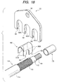
- the flange in terms of its form may be formed in a transversely wide shape as in the case of a flange 180 in a modification shown in Fig. 18, and may be provided with three U-shaped slot portions 181 in its bottom side.
- a bolt inserting hole 182 is formed in a central upper end of the flange 180.
Abstract
Description
Claims (10)
- A shield connector which covers a shielding layer exposed at a terminal portion of a shielding wire and is fixed to said shielding wire, and which is attached to a mating shielding wall to conductingly connect said sealing layer and said mating shielding wall,
said shield connector comprising:an electrically conductive flange having electrical conductivity and adapted to abut against said mating shielding wall;en electrically conductive tubular portion provided in a state of being electrically conducting with said electrically conductive flange and fitted to an inner side or an outer side of said exposed shielding layer so as to be conductingly connected to said shielding layer; anda housing fixed to said shielding wire to hold said electrically conductive flange. - The shield connector according to claim 1, further comprising:
an auxiliary sleeve fitted to said electrically conductive tubular portion with said shielding layer placed therebetween. - The shield connector according to claim 1, wherein
said electrically conductive tubular portion and said shielding layer are fused to each other. - The shield connector according to any one of claims 1 to 3, wherein
said housing is molded by charging a molten resin into a mold for resin molding in a state in which said shielding wire is placed inside said mold. - The shield connector according to claim 4, furher comprising:
a waterproofing tubular portion in which a synthetic resin softer than said housing is molded on an outer peripheral surface of said shielding wire prior to molding said housing provided on an inner side of a rear end portion of said housing. - The shield connector according to claim 4 or 5, wherein
a resin flowing-in hole for allowing a molten resin to pass therethrough is penetratingly formed in said electrically conductive flange. - A shield connector which covers a shielding layer exposed at a terminal portion of a shielding wire and is fixed to said shielding wire, and which is attached to a mating shielding wall to conductingly connect said sealing layer and said mating shielding wall,
said shield connector comprising:an electrically conductive flange having electrical conductivity and adapted to abut against said mating shielding wall;a U-shaped slot portion formed in said electrically conductive flange and adapted to accommodate an exposed portion of said shielding layer of said shielding wire and to be conductingly connected to said shielding layer; anda housing molded by disposing said shielding wire together with said electrically conductive flange in a mold for resin molding and by charging a resin into the mold. - The shield connector according to claim 7, further comprising:
an inner sleeve fitted on an inner side of said shielding layer and adapted to clamp said shielding layer in cooperation with an inner surface of said U-shaped slot portion. - The shield connector according to claim 7, further comprising:
an auxiliary barrel extending along said shielding wire and having at one end thereof a crimping portion for said shielding layer and at another end thereof a U-shaped curved portion for being brought into close contact with an inner surface of said U-shaped slot portion. - The shield connector according to any one of claims 7 to 9, further comprising:
a waterproof tubular portion in which a synthetic resin softer than said housing is molded on an outer peripheral surface of said shielding wire prior to molding said housing provided on an inner side of a rear end portion of said housing.
Applications Claiming Priority (4)
| Application Number | Priority Date | Filing Date | Title |
|---|---|---|---|
| JP2000046947 | 2000-02-24 | ||
| JP2000046947 | 2000-02-24 | ||
| JP2000049795A JP4009050B2 (en) | 1999-04-15 | 2000-02-25 | Shield connector |
| JP2000049795 | 2000-02-25 |
Publications (2)
| Publication Number | Publication Date |
|---|---|
| EP1128472A1 true EP1128472A1 (en) | 2001-08-29 |
| EP1128472B1 EP1128472B1 (en) | 2003-06-11 |
Family
ID=26585965
Family Applications (1)
| Application Number | Title | Priority Date | Filing Date |
|---|---|---|---|
| EP00122154A Expired - Lifetime EP1128472B1 (en) | 2000-02-24 | 2000-10-12 | Shield connector |
Country Status (3)
| Country | Link |
|---|---|
| US (1) | US6398563B1 (en) |
| EP (1) | EP1128472B1 (en) |
| DE (1) | DE60003279T2 (en) |
Cited By (2)
| Publication number | Priority date | Publication date | Assignee | Title |
|---|---|---|---|---|
| WO2013168818A1 (en) * | 2012-05-07 | 2013-11-14 | Yazaki Corporation | Connection structure of external conductor terminal of electric cable |
| CN108288769A (en) * | 2016-12-20 | 2018-07-17 | 矢崎总业株式会社 | Terminal compression joint constructs and the connector of tape cable |
Families Citing this family (14)
| Publication number | Priority date | Publication date | Assignee | Title |
|---|---|---|---|---|
| US6595789B2 (en) * | 2000-10-20 | 2003-07-22 | Autonetworks Technologies, Ltd. | Electronic unit, shield cable connecting structure, connecting method, wires waterproof-connecting structure, and method |
| JP3928770B2 (en) * | 2001-01-17 | 2007-06-13 | 矢崎総業株式会社 | Terminal processing structure of shielded wire |
| JP4082602B2 (en) * | 2003-10-24 | 2008-04-30 | 矢崎総業株式会社 | Connection structure of shielded wire |
| DE102006002774A1 (en) * | 2006-01-20 | 2007-08-02 | Hirschmann Automotive Gmbh | Vibration decoupled contact subzone of a plug or a coupler of a connector |
| JP4331176B2 (en) * | 2006-03-02 | 2009-09-16 | トヨタ自動車株式会社 | Case for electrical equipment and manufacturing method thereof |
| JP5070021B2 (en) * | 2007-12-05 | 2012-11-07 | 矢崎総業株式会社 | connector |
| US7503776B1 (en) * | 2007-12-07 | 2009-03-17 | Lear Corporation | Grounding connector for a shielded cable |
| FR2954607B1 (en) * | 2009-12-23 | 2019-10-18 | Valeo Systemes Thermiques | CONNECTION DEVICE FOR POWERING ELECTRICAL EQUIPMENT |
| JP5622307B2 (en) * | 2010-07-05 | 2014-11-12 | 矢崎総業株式会社 | Shield connector |
| JP5708532B2 (en) | 2012-03-08 | 2015-04-30 | 株式会社オートネットワーク技術研究所 | Electric wire with terminal |
| DE102014220016A1 (en) | 2014-10-02 | 2016-04-07 | Sumitomo Electric Bordnetze Gmbh | Device for electromagnetically compatible connection of electrical conductors with shielding layer |
| JP6955219B2 (en) * | 2018-03-30 | 2021-10-27 | 住友電装株式会社 | Wire harness |
| JP6762339B2 (en) * | 2018-05-21 | 2020-09-30 | 矢崎総業株式会社 | Terminal crimping method and crimping structure |
| JP7379085B2 (en) * | 2019-10-25 | 2023-11-14 | タイコエレクトロニクスジャパン合同会社 | Crimp structure |
Citations (4)
| Publication number | Priority date | Publication date | Assignee | Title |
|---|---|---|---|---|
| GB1276307A (en) * | 1969-03-13 | 1972-06-01 | British Aircraft Corp Ltd | Improvements relating to electrical connector assemblies |
| FR2601196A1 (en) * | 1986-07-04 | 1988-01-08 | Axon Cable Sa | Connector for multi-coaxial cables having insulation-displacement contacts |
| EP0818854A1 (en) * | 1996-07-08 | 1998-01-14 | Amphenol Corporation | Electrical connector and cable termination system |
| FR2768563A1 (en) * | 1997-09-16 | 1999-03-19 | Axon Cable Sa | Electromagnetic screening protection cable |
Family Cites Families (4)
| Publication number | Priority date | Publication date | Assignee | Title |
|---|---|---|---|---|
| US6107572A (en) * | 1994-07-29 | 2000-08-22 | Sumitomo Wiring Systems, Ltd. | Terminal-processed structure of shielded cable and terminal-processing method of the same |
| JP3485150B2 (en) | 1997-07-02 | 2004-01-13 | 矢崎総業株式会社 | Shield connector |
| US5998736A (en) * | 1998-01-20 | 1999-12-07 | Relight America, Inc. | High voltage wiring system for neon lights |
| US6261108B1 (en) * | 1999-04-15 | 2001-07-17 | Harness System Technologies Research, Ltd. | Shield connector |
-
2000
- 2000-10-12 EP EP00122154A patent/EP1128472B1/en not_active Expired - Lifetime
- 2000-10-12 US US09/686,905 patent/US6398563B1/en not_active Expired - Fee Related
- 2000-10-12 DE DE60003279T patent/DE60003279T2/en not_active Expired - Lifetime
Patent Citations (4)
| Publication number | Priority date | Publication date | Assignee | Title |
|---|---|---|---|---|
| GB1276307A (en) * | 1969-03-13 | 1972-06-01 | British Aircraft Corp Ltd | Improvements relating to electrical connector assemblies |
| FR2601196A1 (en) * | 1986-07-04 | 1988-01-08 | Axon Cable Sa | Connector for multi-coaxial cables having insulation-displacement contacts |
| EP0818854A1 (en) * | 1996-07-08 | 1998-01-14 | Amphenol Corporation | Electrical connector and cable termination system |
| FR2768563A1 (en) * | 1997-09-16 | 1999-03-19 | Axon Cable Sa | Electromagnetic screening protection cable |
Cited By (4)
| Publication number | Priority date | Publication date | Assignee | Title |
|---|---|---|---|---|
| WO2013168818A1 (en) * | 2012-05-07 | 2013-11-14 | Yazaki Corporation | Connection structure of external conductor terminal of electric cable |
| US9660355B2 (en) | 2012-05-07 | 2017-05-23 | Yazaki Corporation | Connection structure of external conductor terminal of electric cable |
| CN108288769A (en) * | 2016-12-20 | 2018-07-17 | 矢崎总业株式会社 | Terminal compression joint constructs and the connector of tape cable |
| CN108288769B (en) * | 2016-12-20 | 2019-12-10 | 矢崎总业株式会社 | terminal crimping structure and connector with cable |
Also Published As
| Publication number | Publication date |
|---|---|
| US6398563B1 (en) | 2002-06-04 |
| EP1128472B1 (en) | 2003-06-11 |
| DE60003279T2 (en) | 2004-05-06 |
| DE60003279D1 (en) | 2003-07-17 |
Similar Documents
| Publication | Publication Date | Title |
|---|---|---|
| EP1128472B1 (en) | Shield connector | |
| US8827569B2 (en) | Connector | |
| US6468110B2 (en) | Shielded-cable connector improved in transmission characteristics | |
| JP3401515B2 (en) | Improved two-part male pin connector | |
| US9455525B2 (en) | Connector with flexible conductive member to isolate terminal from vibrations in a wire | |
| US20140120763A1 (en) | Connector | |
| EP1098397B1 (en) | Equipment direct-mounting type shield electric connector assembly | |
| EP1045476A2 (en) | Cable shield grounding connector | |
| JP4270782B2 (en) | Shield terminal for coaxial cable | |
| US20210351539A1 (en) | Male connector and connector device | |
| US20230261424A1 (en) | Electromagnetic shield connector | |
| JPH06203919A (en) | Shielding connector | |
| JP2001313100A (en) | Shield connector | |
| JP4009050B2 (en) | Shield connector | |
| JP4602264B2 (en) | Shield connector | |
| JP6913070B2 (en) | Shield connector | |
| JPH07263082A (en) | Shielding connector | |
| JP3595132B2 (en) | Shield structure of shield connector directly attached to equipment | |
| US11335476B2 (en) | Wire harness | |
| JP2916570B2 (en) | Electrical connection terminal | |
| JP4392381B2 (en) | Shield connector | |
| JP3174236B2 (en) | Braided connection structure of shielded connector | |
| JP3281597B2 (en) | Termination structure of shielded wires | |
| JP3375280B2 (en) | Shield connector | |
| JP5064983B2 (en) | Butt shield connector assembly kit and shield cable harness |
Legal Events
| Date | Code | Title | Description |
|---|---|---|---|
| PUAI | Public reference made under article 153(3) epc to a published international application that has entered the european phase |
Free format text: ORIGINAL CODE: 0009012 |
|
| AK | Designated contracting states |
Kind code of ref document: A1 Designated state(s): AT BE CH CY DE DK ES FI FR GB GR IE IT LI LU MC NL PT SE Kind code of ref document: A1 Designated state(s): DE FR GB |
|
| AX | Request for extension of the european patent |
Free format text: AL;LT;LV;MK;RO;SI |
|
| 17P | Request for examination filed |
Effective date: 20011115 |
|
| AKX | Designation fees paid |
Free format text: DE FR GB |
|
| 17Q | First examination report despatched |
Effective date: 20020610 |
|
| GRAH | Despatch of communication of intention to grant a patent |
Free format text: ORIGINAL CODE: EPIDOS IGRA |
|
| RAP1 | Party data changed (applicant data changed or rights of an application transferred) |
Owner name: AUTONETWORKS TECHNOLOGIES, LTD. Owner name: SUMITOMO WIRING SYSTEMS, LTD. Owner name: SUMITOMO ELECTRIC INDUSTRIES, LTD. |
|
| GRAH | Despatch of communication of intention to grant a patent |
Free format text: ORIGINAL CODE: EPIDOS IGRA |
|
| GRAA | (expected) grant |
Free format text: ORIGINAL CODE: 0009210 |
|
| RIN1 | Information on inventor provided before grant (corrected) |
Inventor name: ICHIDA, KIYOFUMI,HARNESS SYSTEM TECHNOLOGIES RES Inventor name: SANO, ICHIAKI,HARNESS SYSTEM TECHNOLOGIES RES Inventor name: NOZAKI, TAKAO,HARNESS SYSTEM TECHNOLOGIES RES Inventor name: KANAGAWA, SYUUIHI,HARNESS SYSTEM TECHNOLOGIES RES |
|
| AK | Designated contracting states |
Designated state(s): DE FR GB |
|
| PG25 | Lapsed in a contracting state [announced via postgrant information from national office to epo] |
Ref country code: FR Free format text: LAPSE BECAUSE OF FAILURE TO SUBMIT A TRANSLATION OF THE DESCRIPTION OR TO PAY THE FEE WITHIN THE PRESCRIBED TIME-LIMIT Effective date: 20030611 |
|
| REG | Reference to a national code |
Ref country code: GB Ref legal event code: FG4D |
|
| REF | Corresponds to: |
Ref document number: 60003279 Country of ref document: DE Date of ref document: 20030717 Kind code of ref document: P |
|
| PLBE | No opposition filed within time limit |
Free format text: ORIGINAL CODE: 0009261 |
|
| STAA | Information on the status of an ep patent application or granted ep patent |
Free format text: STATUS: NO OPPOSITION FILED WITHIN TIME LIMIT |
|
| 26N | No opposition filed |
Effective date: 20040312 |
|
| EN | Fr: translation not filed | ||
| PG25 | Lapsed in a contracting state [announced via postgrant information from national office to epo] |
Ref country code: GB Free format text: LAPSE BECAUSE OF NON-PAYMENT OF DUE FEES Effective date: 20041012 |
|
| GBPC | Gb: european patent ceased through non-payment of renewal fee |
Effective date: 20041012 |
|
| PGFP | Annual fee paid to national office [announced via postgrant information from national office to epo] |
Ref country code: DE Payment date: 20121010 Year of fee payment: 13 |
|
| REG | Reference to a national code |
Ref country code: DE Ref legal event code: R119 Ref document number: 60003279 Country of ref document: DE Effective date: 20140501 |
|
| PG25 | Lapsed in a contracting state [announced via postgrant information from national office to epo] |
Ref country code: DE Free format text: LAPSE BECAUSE OF NON-PAYMENT OF DUE FEES Effective date: 20140501 |