EP1128394A2 - Beschleunigerbetriebene, gasgekühlte Transmutationsvorrichtung für transuranische Elemente - Google Patents
Beschleunigerbetriebene, gasgekühlte Transmutationsvorrichtung für transuranische Elemente Download PDFInfo
- Publication number
- EP1128394A2 EP1128394A2 EP01300204A EP01300204A EP1128394A2 EP 1128394 A2 EP1128394 A2 EP 1128394A2 EP 01300204 A EP01300204 A EP 01300204A EP 01300204 A EP01300204 A EP 01300204A EP 1128394 A2 EP1128394 A2 EP 1128394A2
- Authority
- EP
- European Patent Office
- Prior art keywords
- fissile material
- layer
- fissile
- recited
- housing
- Prior art date
- Legal status (The legal status is an assumption and is not a legal conclusion. Google has not performed a legal analysis and makes no representation as to the accuracy of the status listed.)
- Withdrawn
Links
Images


Classifications
-
- G—PHYSICS
- G21—NUCLEAR PHYSICS; NUCLEAR ENGINEERING
- G21G—CONVERSION OF CHEMICAL ELEMENTS; RADIOACTIVE SOURCES
- G21G1/00—Arrangements for converting chemical elements by electromagnetic radiation, corpuscular radiation or particle bombardment, e.g. producing radioactive isotopes
- G21G1/04—Arrangements for converting chemical elements by electromagnetic radiation, corpuscular radiation or particle bombardment, e.g. producing radioactive isotopes outside nuclear reactors or particle accelerators
- G21G1/10—Arrangements for converting chemical elements by electromagnetic radiation, corpuscular radiation or particle bombardment, e.g. producing radioactive isotopes outside nuclear reactors or particle accelerators by bombardment with electrically charged particles
Definitions
- the present invention pertains generally to devices and methods for the destruction of high level radioactive waste. More particularly, the present invention pertains to devices which use neutrons to transmute high level radioactive waste into more stable, less radiotoxic materials. The present invention is particularly, but not exclusively, useful for transmuting minor actinides, toxic fission products and plutonium into stable isotopes in a single process.
- spent nuclear fuel is highly radiotoxic and poses several challenging threats to centuries including; nuclear proliferation, radiation exposure and environmental contamination.
- spent fuel assemblies are generated each year, so that it is estimated there will be about 70,000 tons of spent fuel waste by the year 2015.
- this high level radioactive waste is stored 'temporarily'.
- About 95% of this radiotoxic material is temporarily stored at the point of generation (i.e. at the power plant), awaiting a long term solution.
- the high level radioactive waste is primarily stored in water pools, with a small amount being stored in dry storage (casks).
- casks dry storage
- Another solution is to transmute high-level radioactive waste into one or more stable, less radioactive isotopes.
- One source of high-level radioactive waste that is of particular concern here is the spent fuel removed from a typical commercial nuclear power plant. Generally, this spent fuel contains four major constituents; uranium (about 96%), plutonium (1%), minor actinides (0.1%) and fission products (balance). The uranium and a portion of the fission products become no more radiotoxic than natural uranium ore in a relatively short time, and consequently, do not require special burial or transmutation.
- the remaining constituents including the plutonium, minor actinides and a portion of the fission products such as Iodine and Technetium (hereafter referred to as toxic fission products) require special burial or transmutation.
- the spent fuel must be separated into the following four groups; plutonium, minor actinides, toxic fission products and non-radiotoxic materials.
- the radiotoxic constituents can be transmuted by reaction with neutrons into one or more stable isotopes.
- the separated plutonium can first be transmuted by reaction with neutrons in a self-sustaining, critical, thermal neutron reaction.
- a self-sustaining critical reaction a large percentage of the plutonium will transmute into more stable, less radiotoxic isotopes.
- additional levels of plutonium transmutation can be obtained in a sub-critical thermal neutron reaction.
- thermal neutrons i.e.
- neutrons having energies of less than approximately 100eV must be supplied from a source such as a particle accelerator.
- the minor actinides which are separated from the spent fuel can be transmuted to one or more stable, less radiotoxic isotopes. Specifically, this can be accomplished by the reaction of the minor actinides, which are considered non-fissile, with fast neutrons (i.e. neutrons having energies greater than approximately 100eV). It is further known that fast neutrons can be generated by bombarding a spallation target with a beam of protons which are generated by a particle accelerator. Further, it is recognized in the pertinent art that toxic fission products separated from the spent fuel can be successfully transmuted into more stable, less radiotoxic isotopes by reaction of the toxic fission products with externally supplied thermal neutrons.
- an object of the present invention to provide devices suitable for transmuting plutonium, minor actinides and toxic fission products in a single process. It is another object of the present invention to provide passively safe devices for the transmutation of separated spent radioactive fuel. It is yet another object of the present invention to provide devices that are capable of simultaneously transmuting both fissile and non-fissile radioactive materials. It is yet another object of the present invention to provide accelerator driven transmutation devices which are efficiently sized after taking advantage of plutonium's ability to undergo a critical, self-sustaining thermal neutron fission reaction. Yet another object of the present invention is to provide transmutation devices which are easy to use, relatively simple to manufacture, and comparatively cost effective.
- a transuranic transmuter for transmuting high-level radioactive waste includes a sealable, cylindrical housing having a window that allows a beam of protons to pass through the window and into the housing.
- a spallation target is positioned inside the housing and along the proton beam path. Fast neutrons are thereby generated when the beam of protons enters the housing and strikes the spallation target.
- Conductive tubes containing minor actinide microspheres are positioned as a layer inside the housing and immediately adjacent to the spallation target. Specifically, these tubes are positioned inside the housing to partially surround the spallation target.
- the minor actinide microspheres are approximately 1.5mm in diameter and coated with ceramic material.
- a block of graphite formed with recesses to hold toxic fission products and plutonium is positioned behind the tubes containing the minor actinides to interpose the minor actinides between the spallation target and the graphite block.
- the plutonium and toxic fission products are formed as 1.5mm microspheres and coated with ceramic. Within the graphite block, the toxic fission products are positioned in recesses that are closer to the spallation target than the recesses containing the plutonium.
- Helium is circulated through the housing and between the conductive tubes to regulate the temperature inside the housing. Also, the graphite block is formed with cooling channels to further allow the helium to circulate within the graphite block.
- the transmutation of the radiotoxic material can be efficiently conducted in a two-step process.
- a critical, self-sustaining, thermal neutron fission reaction can be initiated in the plutonium with the proton source de-energized.
- further transmutation of the radiotoxic materials may be achieved with the proton source energized.
- the critical, self-sustaining, thermal neutron fission reaction initiated in the plutonium will produce fast neutrons. These fast neutrons will radiate from the plutonium towards the toxic fission products and the minor actinides. Since the plutonium is held in a moderating graphite block, the fast neutrons will pass through the moderator before reaching either the minor actinides or the toxic fission products. Nevertheless, some of these neutrons will reach the minor actinides with energies in the fast spectrum, where they will be effective in fissioning a portion of the minor actinides, and creating new fast neutrons to fission additional amounts of minor actinides.
- a beam of protons is directed from the proton source into the housing and onto the spallation target.
- fast neutrons are generated by the target which travel towards the radiotoxic materials.
- a portion of the fast neutrons generated at the spallation target react with the minor actinides, causing the minor actinides to transmute by either fission or neutron capture reactions into one or more stable, less radiotoxic isotopes.
- the residual fast neutrons from the spallation target will enter the graphite block travelling towards the toxic fission products and plutonium. Additionally, the fast neutron fissioning of the minor actinides will generate neutrons, a portion of which will enter the graphite block travelling toward the toxic fission products and the plutonium.
- the neutrons While passing through the moderating graphite block the neutrons will react with the graphite and lose energy. Consequently, within the graphite block, the energies of the neutrons are, on average, highest near the spallation target. After passing through a portion of the graphite block, the moderated neutrons will react with the toxic fission products and the plutonium causing the toxic fission products and the plutonium to transmute into one or more stable, less radiotoxic isotopes. Within the graphite block, the toxic fission products are positioned closer to the spallation target than the plutonium to take advantage of the fact that the toxic fission products transmute more efficiently when reacted with the higher energy, higher flux neutrons.
- the heat generated in the various transmutation processes described above is regulated and controlled by the device of the present invention in several ways.
- Primary temperature regulation is achieved by circulating helium through the inside of the housing. Specifically, helium is circulated inside the housing between the conductive tubes and through cooling channels formed in the graphite block.
- the device of the present invention is designed and configured to be passively safe. Consequently, a melt-down can be avoided in the event of a helium coolant failure.
- the minor actinides are placed in thermally conductive tubes for the purposes of conducting heat away from the minor actinides.
- the ratio of minor actinides to plutonium charged into the transuranic transmuter can be controlled.
- the reaction rates can be controlled by varying the power of the proton beam.
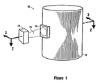
- a transuranic transmuter capable of simultaneously transmuting both fissile and non-fissile radioactive materials in accordance with the present invention is shown and generally designated 10.
- the transuranic transmuter 10 includes a sealable, cylindrical shaped housing 12 having a window 14 to allow a beam of protons 16 to enter the housing 12.
- the housing is formed with a large length to diameter ratio to allow for adequate heat removal.
- the transuranic transmuter 10 includes a proton source 18 such as a particle accelerator.
- a 10 MW proton source 18 capable of emitting protons 16 having energies of approximately 1,000 MeV and a current of approximately 10 mA is suitable for the present invention.
- the protons 16 are directed from the proton source 18 onto a beam path 20 and towards the window 14 of the housing 12.
- a typical beam path 20 for purposes of the present invention has a conical shape and a diameter 21 of about 50 cm, at the window 14 of the housing 12, perpendicular to proton motion.
- An alternate beam path would typically be about 1.6 meters tall and 15 cm wide at the window 14 (not shown).
- the housing 12 is preferably sealable, air-tight and constructed primarily from steel.
- a window 14 is provided to allow the protons 16 to enter the housing 12.
- a spallation target 22 is positioned inside the housing 12 and along the beam path 20. To summarize, the protons 16 emanate from the proton source 18, travel along the beam path 20, enter the housing 12 through the window 14 and strike the spallation target 22.
- the spallation target 22 can be made of any material known in the pertinent art, such as tungsten, which will emit fast neutrons 24 in response to collisions between the protons 16 and the target 22.
- a layer of non-fissile material 26 is positioned adjacent to the spallation target 22.
- the non-fissile material 26 can be held in thermally conductive tubes 28.
- the non-fissile material 26 is preferably formed as a microsphere having a ceramic coating 25 such as silicon carbide. Encapsulation of the radiotoxic material in a ceramic coating that is impervious to water allows for direct post-transmutation burial.
- the microspheres of non-fissile material 26 have a diameter 27 of approximately 1.5mm.
- the thermally conductive tubes 28 both hold the microspheres of non-fissile material 26 and conduct heat that is generated in the transmutation processes away from the non-fissile material 26.
- the conductive tubes 28 may be made from any suitable high temperature, conductive material known in the pertinent art, such as tungsten.
- Fig. 2 shows a representative layer of non-fissile material 26 composed of seven conductive tubes 28 of non-fissile material 26 arranged in a semi-circle immediately adjacent to and partially surrounding the spallation target 22.
- non-fissile material 26 can be any material that is not efficiently transmuted with thermal neutrons.
- the following minor actinides are considered non-fissile materials 26 for present purposes: Americium, Curium and Neptunium.
- the minor actinides such as Americium, Curium and Neptunium can undergo transmutation by either a fission process or a neutron capture process upon reaction with fast neutrons.
- transmute refers to any process which modifies the nucleus of an atom such that the product nucleus has either a different mass number or a different atomic number than the reactant nucleus, and includes the fission, absorption and scattering processes.
- a graphite block moderator 36 is positioned inside the housing 12 to interpose the non-fissile layer 26 between the graphite block moderator 36 and the spallation target 22.
- the graphite block moderator 36 is formed with recesses 40 to hold the toxic fission products 38.
- the toxic fission products 38 are preferable formed as microspheres having a ceramic coating 37 such as silicon carbide.
- the microspheres of toxic fission products 38 have a diameter 39 of approximately 1.5mm.
- the graphite block moderator 36 is also formed with recesses 34 to hold the fissile material 32. As shown in Fig.
- the fissile material 32 is preferable formed as microspheres having a ceramic coating 31 such as silicon carbide.
- the microspheres of fissile material 32 have a diameter 33 of approximately 1.5mm. It is also contemplated for the present invention that the ceramic coated microspheres will be further coated with pyrolitic carbon buffers and other protective coatings that are well known in the pertinent art. Additionally, the ceramic coated microspheres of fissile material 32 may be suspended in carbon matrix pellets 35 within the recesses 34 of the graphite block moderator 36.
- a layer of toxic fission products 38 can be positioned at a distance from the spallation target 22.
- a toxic fission product 38 is a material such as a Technetium or Iodine isotope which can be transmuted with thermal neutrons.
- the toxic fission products 38 as shown are contained in the recesses 40 that are formed in a graphite block moderator 36, any toxic fission products 38 layer configuration known in the pertinent art may be used.
- a fissile layer 32 may be positioned at a distance from the spallation target 22.
- the fissile layer 32 is positioned further from the spallation target 22 than the toxic fission products layer 38.
- eighteen recesses 34 of fissile material 32 making up a representative layer are shown arranged in a semi-circle behind the layer of toxic fission products 38 to interpose both the layer of non-fissile material 26 and the layer of toxic fission products 38 between the spallation target 22 and the fissile material 32.
- a fissile material 32 is a material such as a plutonium or uranium isotope which efficiently fissions upon reaction with thermal neutrons. It is contemplated for the present invention that the plutonium may be GT-MHR particle fuel type plutonium. Although the fissile material 32 is shown contained in recesses 34 formed in a graphite block moderator 36, any other configuration known in the pertinent art may be used for the layer of fissile material 32.
- the transmutation of the radiotoxic material can be efficiently conducted in a two step process.
- a critical, self-sustaining, thermal neutron fission reaction can be initiated in the fissile layer 32 with the proton source 18 de-energized.
- further transmutation of the radiotoxic materials 26, 32, 38 may be achieved with the proton source 18 energized.
- the first step may not be required.
- the transuranic transmuter 10 is efficiently sized to take advantage of the two-step transmutation process discussed above.
- the radiotoxic material 26, 32, 38 is placed in the transuranic transmuter 10, and a critical, self-sustaining, thermal neutron fission reaction is initiated and allowed to proceed until a predetermined amount of fissile material 32 remains. Allowing the fissile material 32 to first transmute in a critical, self-sustaining, thermal neutron fission reaction, followed by transmutation in a non-critical thermal neutron fission reaction provides several advantages over a one-step process where all transmutation occurs with the proton source 18 energized. First, the transuranic transmuter 10 can be constructed with a smaller, less powerful proton source 18. Second, since a portion of the transmutation occurs with the proton source de-energized, energy is conserved.
- the dimensions of the transuranic transmuter 10 can be reduced.
- the critical, self-sustaining, thermal neutron fission reaction (first step) could be conducted at a commercial reactor, in which case the transuranic transmuter 10 described above will be properly sized to complete the non-critical thermal neutron fission reaction (second step).
- the first step takes advantage of the fact that fissile materials 32 such as Plutonium can undergo a critical, self-sustaining, thermal neutron fission reaction. Consequently, in the absence of an external supply of thermal neutrons, a critical, self-sustaining, thermal neutron fission reaction can be initiated in the fissile material 32 resulting in a portion of the fissile material 32 being transmuted into one or more stable isotopes. Specifically, a portion of the fissile material 32 can be transmuted in a critical, self-sustaining, thermal neutron fission reaction prior to energizing the proton source 18. However, the critical, self-sustaining, thermal neutron fission reaction can only continue while a critical amount of fissile material 32 is present. As the reaction proceeds, the amount of fissile material 32 decreases until the reaction is no longer self-sustaining. Consequently, only a portion of the fissile material 32 can be transmuted prior to energizing the proton source 18.
- the critical, self-sustaining, thermal neutron fission reaction initiated in the fissile layer 32 will produce fast neutrons 24a,b. These fast neutrons 24a,b will radiate from the fissile layer 32 towards the toxic fission products 38 and the non-fissile layer 26. Since the fissile material 32 is held in a graphite block moderator 36, the fast neutrons 24a,b generated in the fissile layer 32 will pass through the graphite block moderator 36 before reaching either the non-fissile layer 26 or the toxic fission products 38. Nevertheless, some neutrons, such as neutron 24a shown in Fig.
- the duration of the first step will be approximately three years.
- Additional transmutation of the radiotoxic material 26, 32, 38 can be achieved in the second step with the proton source 18 energized. It is contemplated for the present invention that the duration of the second step will be approximately one year.
- a beam of protons 16 is directed from the proton source 18 into the housing and onto the spallation target 22. As the protons 16 impact the spallation target 22, fast neutrons 24c,d are generated by the target 22 and travel towards the radiotoxic materials 26, 32, 38. A portion of the fast neutrons generated at the spallation target, such as neutron 24c shown in Fig.
- the residual fast neutrons 24d While passing through the graphite block moderator 36 the residual fast neutrons 24d will react with the graphite block moderator 36 and lose energy. Consequently, within the graphite block moderator 36, the energies of the residual neutrons 24d will be highest near the spallation target. After passing through a portion of the graphite block moderator 36, the moderated residual neutrons 24d will react with the toxic fission products 38 and the fissile material 32 causing the toxic fission products 38 and the fissile material 32 to transmute into more stable, less radiotoxic isotopes.
- the toxic fission products 38 are positioned closer to the spallation target 22 than the fissile material 32 to take advantage of the fact that the toxic fission products 38 transmute at a faster rate when reacted with the higher energy, higher flux, residual neutrons 24d.
- each radiotoxic material 26, 32, 38 may generate neutrons 24e as a by-product of the fission reaction.
- Fig. 2 shows a representative generated neutron 24e emanating from the non-fissile material 26 and passing through the conductive tube 28. These neutrons 24e that are generated by the transmutation reactions are available for further transmutation of the radiotoxic materials 26, 32, 38.
- transmutation processes described above are known to generate heat at a process specific rate, and the heat generated must be controlled or removed from the transmuting material 26, 32, 38 to prevent overheating, melting or damage to the transuranic transmuter 10.
- the transuranic transmuter 10 has been constructed with several design features to control or remove heat from the transmuting material 26, 32, 38.
- a helium source 48 and circulator 50 are provided to circulate helium (forced cooling) as a coolant through the inside of the housing 12 and between the conductive tubes 28.
- the graphite block moderator 36 is formed with cooling channels 44 to allow helium to be circulated within the graphite block moderator 36.
- Helium is chosen because it is virtually transparent to neutrons. Additionally, helium is chemically inert, and consequently, nuclear and chemical coolant-fuel interactions are minimized. Further, the helium remains in the gaseous state providing reliable cooling that is easy to calculate and predict. Still further, protons 16 at the expected energies (see discussion above) can travel with essentially no energy loss through helium gas for several kilometers. As shown in Fig. 3, helium is circulated within the entire housing 12, and consequently, the beam of protons 16 must pass through the gaseous helium on the beam path 20 between the window 14 and the spallation target 22.
- the non-fissile material 26 is held in conductive tubes 28 to allow heat generated within the non-fissile material 26 to be conducted to the outside 42 of the tube 28.
- the energy level of the beam of protons 16 can be controlled to modify the amount of fast neutrons generated at the spallation target 22. Consequently, the rate of transmutation and the corresponding rate of heat generation can be controlled by varying the energy of the beam of protons 16.
- the ratio of non-fissile material 26 (undergoing fast neutron transmutation) to fissile material 32 (undergoing primarily thermal neutron transmutation) can be held small to avoid excessive heat generation.
- spent fuel from commercial reactors generally contains approximately ten times more plutonium than minor actinides.
- the transmuter 10 will be passively safe. Specifically, overheating can be avoided in the event of a failure in the helium source 48.
Landscapes
- Chemical & Material Sciences (AREA)
- Chemical Kinetics & Catalysis (AREA)
- General Chemical & Material Sciences (AREA)
- Physics & Mathematics (AREA)
- Engineering & Computer Science (AREA)
- General Engineering & Computer Science (AREA)
- High Energy & Nuclear Physics (AREA)
- Particle Accelerators (AREA)
Applications Claiming Priority (2)
| Application Number | Priority Date | Filing Date | Title |
|---|---|---|---|
| US511749 | 2000-02-24 | ||
| US09/511,749 US6472677B1 (en) | 2000-02-24 | 2000-02-24 | Devices and methods for transmuting materials |
Publications (2)
| Publication Number | Publication Date |
|---|---|
| EP1128394A2 true EP1128394A2 (de) | 2001-08-29 |
| EP1128394A3 EP1128394A3 (de) | 2003-01-08 |
Family
ID=24036267
Family Applications (1)
| Application Number | Title | Priority Date | Filing Date |
|---|---|---|---|
| EP01300204A Withdrawn EP1128394A3 (de) | 2000-02-24 | 2001-01-10 | Beschleunigerbetriebene, gasgekühlte Transmutationsvorrichtung für transuranische Elemente |
Country Status (3)
| Country | Link |
|---|---|
| US (1) | US6472677B1 (de) |
| EP (1) | EP1128394A3 (de) |
| JP (1) | JP2001264487A (de) |
Cited By (6)
| Publication number | Priority date | Publication date | Assignee | Title |
|---|---|---|---|---|
| WO2005001849A1 (fr) * | 2003-06-27 | 2005-01-06 | Eremeev, Petr Igorevich | Procede de prise en charge du combustible nucleaire epuise |
| EP1509927A4 (de) * | 2002-05-17 | 2007-04-04 | Oregon State | Verarbeiten radioaktiver materialien mit wasserstoffisotopkernen |
| US20110169492A1 (en) * | 2007-11-28 | 2011-07-14 | Groves Joel L | Neutron generator |
| CN101061552B (zh) * | 2002-10-25 | 2011-11-02 | 通用原子公司 | 放射性废物的分解系统和方法 |
| CN110335697A (zh) * | 2019-07-11 | 2019-10-15 | 四川大学 | 一种高丰度98Tc的制备方法 |
| CN111128431A (zh) * | 2020-01-02 | 2020-05-08 | 中国原子能科学研究院 | 用于生产放射性同位素的靶件制备方法、靶体及用于承载靶件的组件 |
Families Citing this family (13)
| Publication number | Priority date | Publication date | Assignee | Title |
|---|---|---|---|---|
| FR2806206B1 (fr) * | 2000-03-08 | 2002-04-26 | Commissariat Energie Atomique | Procede d'incineration d'elements chimiques transuraniens et reacteur nucleaire mettant en oeuvre ce procede |
| US6974720B2 (en) * | 2003-10-16 | 2005-12-13 | Cree, Inc. | Methods of forming power semiconductor devices using boule-grown silicon carbide drift layers and power semiconductor devices formed thereby |
| US20090238321A1 (en) * | 2008-03-20 | 2009-09-24 | Areva Np Inc. | Nuclear power plant with actinide burner reactor |
| JP5522427B2 (ja) * | 2009-02-20 | 2014-06-18 | 独立行政法人日本原子力研究開発機構 | 長寿命核分裂生成物を短寿命核種へ変換する方法 |
| EP2532006B1 (de) | 2010-02-04 | 2015-04-22 | General Atomics | Kernspaltungsreaktor |
| CA2713972A1 (en) * | 2010-07-27 | 2012-01-27 | Mevex Corporation | Power concentrator for electron and/or x-ray beams |
| US10535441B1 (en) | 2010-07-27 | 2020-01-14 | Mevex Corporation | Method of irradiating a target |
| US10332646B2 (en) * | 2011-12-05 | 2019-06-25 | Wisconsin Alumni Research Foundation | Apparatus and method for generating medical isotopes |
| JP2015519586A (ja) * | 2012-06-15 | 2015-07-09 | デント インターナショナル リサーチ,インコーポレイテッド | 元素を変換するための装置及び方法 |
| US10706982B2 (en) * | 2012-11-23 | 2020-07-07 | Péter Teleki | Combined moderator/target for neutron activation process |
| EP3806110A1 (de) * | 2015-12-15 | 2021-04-14 | Clear Inc. | Kernreaktorsystem zum löschen von radioaktivität |
| CN110444312B (zh) * | 2019-09-03 | 2020-12-29 | 中国科学院近代物理研究所 | 利用干馏法从铀裂变产物中分离医用同位素131i的方法 |
| CN113488204B (zh) * | 2021-07-12 | 2023-07-25 | 西南科技大学 | 一种用于快中子堆的套管式ma嬗变棒 |
Family Cites Families (5)
| Publication number | Priority date | Publication date | Assignee | Title |
|---|---|---|---|---|
| US4780682A (en) | 1987-10-20 | 1988-10-25 | Ga Technologies Inc. | Funnel for ion accelerators |
| US4987007A (en) | 1988-04-18 | 1991-01-22 | Board Of Regents, The University Of Texas System | Method and apparatus for producing a layer of material from a laser ion source |
| US5160696A (en) * | 1990-07-17 | 1992-11-03 | The United States Of America As Represented By The United States Department Of Energy | Apparatus for nuclear transmutation and power production using an intense accelerator-generated thermal neutron flux |
| US5513226A (en) * | 1994-05-23 | 1996-04-30 | General Atomics | Destruction of plutonium |
| US6233298B1 (en) * | 1999-01-29 | 2001-05-15 | Adna Corporation | Apparatus for transmutation of nuclear reactor waste |
-
2000
- 2000-02-24 US US09/511,749 patent/US6472677B1/en not_active Expired - Fee Related
-
2001
- 2001-01-10 EP EP01300204A patent/EP1128394A3/de not_active Withdrawn
- 2001-02-16 JP JP2001040240A patent/JP2001264487A/ja active Pending
Cited By (9)
| Publication number | Priority date | Publication date | Assignee | Title |
|---|---|---|---|---|
| EP1509927A4 (de) * | 2002-05-17 | 2007-04-04 | Oregon State | Verarbeiten radioaktiver materialien mit wasserstoffisotopkernen |
| CN101061552B (zh) * | 2002-10-25 | 2011-11-02 | 通用原子公司 | 放射性废物的分解系统和方法 |
| WO2005001849A1 (fr) * | 2003-06-27 | 2005-01-06 | Eremeev, Petr Igorevich | Procede de prise en charge du combustible nucleaire epuise |
| US20110169492A1 (en) * | 2007-11-28 | 2011-07-14 | Groves Joel L | Neutron generator |
| US9001956B2 (en) | 2007-11-28 | 2015-04-07 | Schlumberger Technology Corporation | Neutron generator |
| US9204527B2 (en) | 2007-11-28 | 2015-12-01 | Schlumberger Technology Corporation | Neutron generator |
| US9839112B2 (en) | 2007-11-28 | 2017-12-05 | Schlumberger Technology Corporation | Neutron generator |
| CN110335697A (zh) * | 2019-07-11 | 2019-10-15 | 四川大学 | 一种高丰度98Tc的制备方法 |
| CN111128431A (zh) * | 2020-01-02 | 2020-05-08 | 中国原子能科学研究院 | 用于生产放射性同位素的靶件制备方法、靶体及用于承载靶件的组件 |
Also Published As
| Publication number | Publication date |
|---|---|
| JP2001264487A (ja) | 2001-09-26 |
| US6472677B1 (en) | 2002-10-29 |
| EP1128394A3 (de) | 2003-01-08 |
Similar Documents
| Publication | Publication Date | Title |
|---|---|---|
| US6472677B1 (en) | Devices and methods for transmuting materials | |
| US5160696A (en) | Apparatus for nuclear transmutation and power production using an intense accelerator-generated thermal neutron flux | |
| US6738446B2 (en) | System and method for radioactive waste destruction | |
| US9177679B2 (en) | Accelerator-based method of producing isotopes | |
| Abderrahim et al. | Transmutation of high‐level nuclear waste by means of accelerator driven system | |
| Heidet et al. | Accelerator–reactor coupling for energy production in advanced nuclear fuel cycles | |
| Velasquez et al. | Axial neutron flux evaluation in a Tokamak system: a possible transmutation blanket position for a fusion–fission transmutation system | |
| Melville et al. | A theoretical model for the production of Ac-225 for cancer therapy by neutron capture transmutation of Ra-226 | |
| Abderrahim | Contribution of the European Commission to a European Strategy for HLW Management Through Partitioning & Transmutation: Presentation of MYRRHA and Its Role in the European P&T Strategy | |
| Wimmers et al. | Nuclear Physics and Reactor Technologies (Fission and Fusion) | |
| McIntyre et al. | Accelerator-driven subcritical fission in molten salt core: Closing the nuclear fuel cycle for green nuclear energy | |
| Nolen Jr | A target concept for intense radioactive beams in the {sup 132} Sn Region | |
| Eriksson | Accelerator-driven systems: safety and kinetics | |
| Tanabe | Sources of energetic quanta (EQ)(radiation sources) | |
| Pudjorahardjo et al. | High power particle accelerator for driving the nuclear waste transmutation system at nuclear power plant | |
| JP2022062962A (ja) | アクチニウム225の生成方法 | |
| Ripani | Neutron sources and transmutation of nuclear waste | |
| Bevelacqua | Speculative High-Level Nuclear Waste Processing Methods | |
| Moore et al. | The TRIGA Reactor Facility at the Armed Forces Radiobiology Research Institute: A Simplified Technical Description. | |
| Yim | Basic Nuclear Science and Engineering | |
| Baxevanis | Accelerator Driven Subcritical Reactors | |
| Han et al. | Transmutation of 126Sn in spallation targets of accelerator-driven systems | |
| Yu et al. | Nuclear Technology and Safety | |
| CN105513663A (zh) | 用于辐照重化学元素的同位素将核能转化为热的方法以及用于实现该方法的装置(实施例) | |
| Freiwald | Nuclear Terms: a glossary |
Legal Events
| Date | Code | Title | Description |
|---|---|---|---|
| PUAI | Public reference made under article 153(3) epc to a published international application that has entered the european phase |
Free format text: ORIGINAL CODE: 0009012 |
|
| AK | Designated contracting states |
Kind code of ref document: A2 Designated state(s): AT BE CH CY DE DK ES FI FR GB GR IE IT LI LU MC NL PT SE TR |
|
| AX | Request for extension of the european patent |
Free format text: AL;LT;LV;MK;RO;SI |
|
| PUAL | Search report despatched |
Free format text: ORIGINAL CODE: 0009013 |
|
| RIC1 | Information provided on ipc code assigned before grant |
Free format text: 7G 21G 1/10 A, 7G 21C 1/30 B |
|
| AK | Designated contracting states |
Kind code of ref document: A3 Designated state(s): AT BE CH CY DE DK ES FI FR GB GR IE IT LI LU MC NL PT SE TR |
|
| AX | Request for extension of the european patent |
Free format text: AL;LT;LV;MK;RO;SI |
|
| AKX | Designation fees paid |
Designated state(s): DE ES FR GB IT |
|
| STAA | Information on the status of an ep patent application or granted ep patent |
Free format text: STATUS: THE APPLICATION IS DEEMED TO BE WITHDRAWN |
|
| 18D | Application deemed to be withdrawn |
Effective date: 20030709 |