EP1128380A2 - Index position detector for spindle motor and motor apparatus including the same - Google Patents
Index position detector for spindle motor and motor apparatus including the same Download PDFInfo
- Publication number
- EP1128380A2 EP1128380A2 EP00310973A EP00310973A EP1128380A2 EP 1128380 A2 EP1128380 A2 EP 1128380A2 EP 00310973 A EP00310973 A EP 00310973A EP 00310973 A EP00310973 A EP 00310973A EP 1128380 A2 EP1128380 A2 EP 1128380A2
- Authority
- EP
- European Patent Office
- Prior art keywords
- inductor
- circuit board
- rotor yoke
- flange portion
- rotor
- Prior art date
- Legal status (The legal status is an assumption and is not a legal conclusion. Google has not performed a legal analysis and makes no representation as to the accuracy of the status listed.)
- Withdrawn
Links
- 230000004907 flux Effects 0.000 claims abstract description 34
- 238000001514 detection method Methods 0.000 description 22
- 230000000452 restraining effect Effects 0.000 description 7
- 230000000630 rising effect Effects 0.000 description 6
- 230000035945 sensitivity Effects 0.000 description 5
- 238000010276 construction Methods 0.000 description 3
- 230000000873 masking effect Effects 0.000 description 3
- 239000002184 metal Substances 0.000 description 3
- 229910052751 metal Inorganic materials 0.000 description 3
- 229910000519 Ferrosilicon Inorganic materials 0.000 description 2
- XEEYBQQBJWHFJM-UHFFFAOYSA-N Iron Chemical group [Fe] XEEYBQQBJWHFJM-UHFFFAOYSA-N 0.000 description 2
- 229910000831 Steel Inorganic materials 0.000 description 2
- 230000007274 generation of a signal involved in cell-cell signaling Effects 0.000 description 2
- 238000000034 method Methods 0.000 description 2
- 239000004033 plastic Substances 0.000 description 2
- 238000004080 punching Methods 0.000 description 2
- 239000011347 resin Substances 0.000 description 2
- 229920005989 resin Polymers 0.000 description 2
- 239000010959 steel Substances 0.000 description 2
- 239000000758 substrate Substances 0.000 description 2
- 230000007423 decrease Effects 0.000 description 1
- 238000010586 diagram Methods 0.000 description 1
- 230000006698 induction Effects 0.000 description 1
- 239000000696 magnetic material Substances 0.000 description 1
- 230000000737 periodic effect Effects 0.000 description 1
- 230000002093 peripheral effect Effects 0.000 description 1
- 238000005476 soldering Methods 0.000 description 1
Images


Classifications
-
- G—PHYSICS
- G11—INFORMATION STORAGE
- G11B—INFORMATION STORAGE BASED ON RELATIVE MOVEMENT BETWEEN RECORD CARRIER AND TRANSDUCER
- G11B19/00—Driving, starting, stopping record carriers not specifically of filamentary or web form, or of supports therefor; Control thereof; Control of operating function ; Driving both disc and head
- G11B19/20—Driving; Starting; Stopping; Control thereof
- G11B19/28—Speed controlling, regulating, or indicating
Definitions
- the present invention relates to an index position detector for a spindle motor which rotates rotating recording media such as floppy disks, and also relates to a motor apparatus including the index position detector.
- an index signal which provides one pulse for each rotation is required to determine the starting point for writing data.
- the index signal is also used for detecting the rotational condition of the floppy disk, or the motor, so as to provide a ready signal for writing or reading.
- the index signal is also used to start writing in the process of formatting tracks, and to stop the writing when the rotation stops.
- Figs. 10 to 12 conceptually show a construction of a motor apparatus including an index position detector which detects the index position of the spindle motor.
- the motor apparatus includes a mount 101, a circuit board 102 which is mounted on the mount 101, and a rotor yoke 103.
- the mount 101 is constructed of a metal plate, and is provided with three attachment tabs 101a at the periphery thereof.
- Each of the attachment tabs 101a is formed unitarily with the mount 101 and is bent upward in an L-shape.
- the attachment tabs 101a are provided with attachment holes 101b for fixing the mount 101 to a housing of a floppy disk drive (FDD) by screws or by other means.
- FDD floppy disk drive
- the mount 101 is also provided with four restraining hooks 101c at the periphery thereof.
- the restraining hooks 101c are shaped approximately like the letter L and project upward. As shown in Figs. 10 and 11, a part of each of the restraining hooks 101c is bent in the horizontal direction so as to press downward and hold the circuit board 102, which is disposed on the mount 101.
- the circuit board 102 is constructed with an insulated substrate on which wiring patterns and circuit components such as a driver circuit and a driver control circuit (not shown) are mounted.
- the circuit board 102 is provided with a bearing hole 102a at the center thereof, through which a bearing 104 having a shaft hole 104a is inserted.
- the bearing 104 is attached to the mount 101, and is provided with an iron-core member 105.
- the iron-core member 105 has twelve pole pieces 105a which are arranged radially at even intervals, and stator coils 106 are formed around the pole pieces 105a.
- the stator coils 106 may be divided into three types for applying three phases, U-phase, V-phase, and W-phase.
- the iron-core member 105 is constructed of, for example, a laminated iron core formed by punching out a plurality of magnetic steel plates, such as ferrosilicon plates, and stacking them.
- a Hall device 107 for detecting the index position of a rotating recording media is mounted on the circuit board 102, so as to oppose one of the pole pieces 105a.
- the rotor yoke 103 has a shape like a shallow dish inverted on the circuit board 102, including a flange portion 103a at the periphery thereof.
- a ring-type rotor magnet 108 is affixed on the inner wall of the flange portion 103a.
- the rotor magnet 108 is constructed of a resin, such as a rubber or a plastic, containing magnetic material.
- the rotor magnet 108 is equally divided along the periphery thereof into, for example, sixteen portions, which are magnetized so as to alternate S-pole and N-pole.
- a window portion 103b having a predetermined width is formed in the flange portion 103a.
- a pair of dipolar magnets 108a and 108b is provided to the rotor magnet 108 so as to project out through the window portion 103b beyond the periphery of the flange portion 103a.
- the dipolar magnets 108a and 108b may be separated from the rotor magnet 108 and be stuck on the periphery of the rotor magnet 108.
- the rotor yoke 103 is also provided with a shaft 109 which penetrates through the center thereof, and the lower side of the shaft is inserted through the shaft hole 104a formed in the bearing 104. Accordingly, the rotor yoke 103 is rotatably disposed above the circuit board 102 as shown in Fig. 10 so as to cover the stator coils 106, in a manner such that the Hall device 10 opposes the flange portion 103a at the periphery thereof.
- a thrust bearing is disposed under the shaft hole 104a so as to support the shaft 109At the bottom end.
- the shaft 109 Can smoothly rotate while being supported by the shaft hole 104a and the thrust bearing.
- a chucking device for receiving and holding the floppy disk at the center hub thereof (not shown in the figure) is mounted on the rotor yoke 103.
- a three-phase AC power supply applies a three-phase alternating current to the stator coils 106 of three types for U-phase, V-phase and W-phase, by switching the current in a predetermined order. Accordingly, magnetic opposing force is continuously generated between the stator coils 106 and the rotor magnet 108, so that the rotor yoke 103 rotates above the circuit board 102, which is a part of the stator.
- the switching of the current is performed by detecting the rotational position using position detectors, for example, three Hall devices disposed between the stator coils 106, and by using the detection signal as a switching control signal.
- the dipolar magnets 108a and 108b When the rotor yoke 103 of the spindle motor rotates as described above, the dipolar magnets 108a and 108b also rotate along with the rotation of the rotor yoke 103. Accordingly, the dipolar magnets 108a and 108b periodically move toward and away from the Hall device 107. When the dipolar magnets 108a and 108b are away, the Hall device 107 receives a small amount of magnetic flux, so that the detection output is approximately 0. When the dipolar magnets 108a and 108b are in proximity, the Hall device 107 receives sufficient magnetic flux, so that the detection output increases or decreases in accordance with the movement of the dipolar magnets 108a and 108b.
- the detection output is then compared with a predetermined reference voltage to obtain a square wave signal representing the result of the comparison.
- the square wave signal is used for generating an index signal which provides a pulse at the same time when, for example, the square wave signal provides a rising edge.
- the conventional index position detector for the spindle motor has the following problems. That is, an expensive Hall device 107 is required for detecting the magnetic flux from the dipolar magnets 108a and 108b with high sensitivity.
- the window portion 103b must be formed in the flange portion 103a of rotor yoke 103, and the end portions of the dipolar magnets 108a and 108b must project far beyond the window portion 103b. Accordingly, high processing cost is incurred when the dipolar magnets 108a and 108b are combined with the rotor magnet 108.
- an object of the present invention to provide an index position detector for a spindle motor which is free from the above-described problems, and which realizes the detection of the index position by using the rotor yoke with a simple and cost-saving construction which includes the conventional window portion.
- an index position detector for a spindle motor includes a rotor magnet which is provided to an inner surface of a flange portion of a rotor yoke with which the spindle motor is constructed, a window portion formed in the flange portion in a manner such that a part of the rotor magnet faces outside, and an inductor which is disposed in a stator section so as to oppose the periphery of the flange portion and which detects a magnetic flux of the rotor magnet via the window portion.
- the high-sensitivity inductor directly receives the magnetic flux from the part of the rotor magnet which is facing outside via the window portion formed in the flange portion of the rotor yoke.
- the index signal is more reliably obtained based on the detection output from the inductor at low cost by using the conventional rotor yoke.
- the inductor may be disposed so as to oppose the periphery of the flange portion in a manner such that the central axis of a coil contained in the inductor is approximately parallel to the tangential direction of the periphery of the rotor yoke.
- the magnetic flux of the rotor magnet more efficiently affects the inductor via the window portion, so that the sensitivity of the magnetic flux detection by the inductor is increased.
- reliability of the index signal generation is also increased.
- a motor apparatus comprises a circuit board which is disposed above a mount, a rotor yoke which is rotatably supported by the mount, a rotor magnet which is provided to an inner surface of a flange portion of the rotor yoke, stator coils which are disposed between the rotor yoke and the mount and which are arranged radially around the rotational center of the rotor yoke, lands which are provided on the circuit board at positions between the stator coils to connect coil terminals of the stator coils, and an inductor which is mounted on the circuit board so as to oppose the periphery of the flange portion and which detects a magnetic flux of the rotor magnet via the window portion, wherein the circuit board is formed so as not to expand over one side of the mount relative to the rotational center of the rotor yoke.
- the circuit board is formed within one side of the mount, the area of the circuit board is reduced, so that the motor is smaller and lighter.
- the coil terminals of the stator coils are connected to the lands which are provided on the circuit board at positions between the stator coils.
- the magnetic flux of the rotor magnet more efficiently affects the inductor via the window portion, so that the sensitivity of the magnetic flux detection by the inductor is increased.
- reliability of the index signal generation is also increased.
- the lands on which the coil terminals of the stator coils are soldered are provided on the circuit board on which the inductor is mounted, and the area of the circuit board is less than half the area of the mount, in an embodiment.
- the area of the circuit board is reduced.
- the circuit board may be more easily attached to the mount, and a smaller motor may be manufactured at a low cost.
- such a construction is applied so that a part of the rotor magnet disposed inside the rotor yoke faces outside through the window portion via the flange portion.
- the magnetic flux of the rotor magnet affects, through the window portion, the inductor which is disposed at the periphery of the rotor.
- the inductor is disposed so as to oppose the flange portion in a manner such that the central axis of the coil contained in the inductor is approximately parallel to the tangential direction of the rotor yoke. Accordingly, the coil in the inductor may be affected by a weak magnetic flux emanating from parts deeper inside the rotor magnet compared to the part close to the window portion of the rotor yoke, which increases the precision of the index position detection.
- the lands on which the coil terminals of the stator coils with which the spindle motor is constructed are connected to the lands which are provided on the circuit board on which the inductor is mounted.
- the area of the circuit board may be reduced to less than half the area of the metal mount. Accordingly, the circuit board may be more easily attached to the mount, and the cost for the circuit board may be reduced.
- the entire body of the index position detector and the spindle motor may be lighter and smaller.
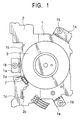
- Fig. 1 is a plan view conceptually showing a motor apparatus including an index position detector for a spindle motor according to the present invention
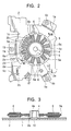
- Fig. 2 is a plan view conceptually showing a stator section of the motor apparatus shown in Fig. 1.
- the spindle motor includes a circuit board 2 which is mounted on a mount 1, and a rotor yoke 3.
- the mount 1 is constructed of a metal plate, and is provided with three attachment tabs la at the periphery thereof. Each of the attachment tabs la is formed unitarily with the mount 1, and is bent upward in an L-shape. In addition, the attachment tabs la are provided with attachment holes 1b, for fixing the mount 1 to a housing of a floppy disk drive by screws or by other means.
- the mount 1 is also provided with two restraining hooks 1c at the periphery thereof. The restraining hooks 1c are shaped approximately like the letter L and project upward.
- the restraining hooks 1c press downward and hold the circuit board 2, one at the periphery thereof and the other at the edge of a through hole 2c formed in the circuit board 2. As shown in Fig. 1, a part of each of the restraining hooks 1c is bent in the horizontal direction so as to press and hold the circuit board 2.
- the circuit board 2 is constructed with an insulated substrate on which wiring patterns and circuit components such as a driver circuit and a driver control circuit (not shown) are mounted.
- the area of the circuit board 2 is half the area of the mount 1, and the circuit board 2 is disposed at the side in which an inductor 7, which will be described below, is provided.
- the circuit board 2 is provided with an opening 2a at one side, through which a bearing 4 having a shaft hole 4a is inserted.
- the bearing 4 is attached to the mount 1, and is provided with an iron-core member 5.
- the iron-core member 5 has twelve pole pieces 5a which are arranged radially at even intervals, and stator coils 6 are formed around the pole pieces 5a.
- the stator coils 6 may be divided into three types for applying three phases, U-phase, V-phase, and W-phase.
- Three coil terminals 6a for the three types of the stator coils 6 and one common coil terminal 6b are soldered on lands 2b provided on the circuit board 2.
- the iron-core member 5 is constructed with, for example, a laminated iron core formed by punching out a plurality of magnetic steel plates, such as ferrosilicon plates, and stacking them.
- the inductor 7 for detecting the index position of the recording medium is disposed as shown in Fig. 1 in a long hole 2d formed in the circuit board 2, so as to oppose one of the pole pieces 5a.
- the circuit board 2 is also provided with a land 2e for soldering lead terminals 7a of the inductor 7.
- the rotor yoke 3 has a shape like a shallow dish inverted on the circuit board 2, including a flange portion 3a at the periphery thereof.
- a ring-type rotor magnet 8 is affixed on the inner wall of the flange portion 3a.
- the rotor magnet 8 comprises a resin, such as a rubber or a plastic, and the cross sectional shape of the rotor magnet 8 does not vary in the circumferential direction.
- the rotor magnet 8 is equally divided along the periphery into, for example, sixteen portions, which are magnetized so as to alternate S-pole and N-pole.
- the flange portion 3a of the rotor yoke 3 is provided with a window portion 3b having a predetermined width, through which a part of the rotor magnet 8 is facing outside. Accordingly, the window portion 3b is not provided with dipolar magnets as in the conventional type.
- the window portion 3b periodically opposes the inductor 7 in accordance with the rotation of the rotor magnet 8.
- the circuit board 2 is also provided with four lands 2f for connecting external leads, and the lands 2f are connected to the lands 2b via electric wires formed on the circuit board 2.
- the rotor yoke 3 is also provided with a shaft 9 which penetrates through the center thereof, and the lower side of the shaft is inserted through the shaft hole 4a formed in the bearing 4. Accordingly, the rotor yoke 3 is disposed above the circuit board 2 as shown in Fig. 1 so as to cover the stator coils 6, in a manner such that the inductor 7 opposes the flange portion 3a at the periphery thereof.
- a thrust bearing 10 is disposed under the shaft hole 4a, so as to support the shaft 9At the bottom end.
- the shaft 9 Can smoothly rotate while being supported by the shaft hole 4a and the thrust bearing 10.
- a chucking device for receiving and holding the floppy disk at the center hub (not shown) is mounted on the rotor yoke 3.
- a three-phase AC power supply applies a three-phase alternating current to the stator coils 106 of three types for U-phase, V-phase, and W-phase, by switching the current in a predetermined order. Accordingly, magnetic opposing force is continuously generated between the stator coils 6 and the rotor magnet 8, so that the rotor yoke 3 rotates above the mount 1 and the circuit board 2, which are a part of the stator.
- the switching of the current is performed by detecting the voltage induced by each of the stator coils to determine the rotational position, and by using the detection signal as a switching control signal.
- three Hall devices required in the conventional motor apparatus may be omitted, and the area of the circuit board 2 may be reduced.
- the rotor magnet 8 which is facing outside via the window portion 3b also rotates along with the rotation of the rotor yoke 3. Accordingly, the outwardly facing part of the rotor magnet 8 periodically moves toward and away from the inductor 7.
- the inductor 7 receives small amount of magnetic flux, so that the inducted voltage is approximately 0.
- the inductor 7 receives sufficient magnetic flux from the rotor magnet 8, so that the voltage induced by the inductor 7 varies proportionally to the time variation of the magnetic flux.
- the induced voltage is then compared with a predetermined reference voltage to obtain a square wave signal representing the result of the comparison.
- the square wave signal is used for generating an index signal which provides a pulse at the same time when, for example, the square wave signal provides a rising edge.
- the inductor 7 is disposed in a manner such that the central axis of a coil contained in the inductor 7 is approximately parallel to the tangential direction of the rotor yoke 3. Accordingly, the amount of magnetic flux which affects the inductor 7 is at a maximum, so that the sensitivity of the magnetic flux detection is sufficiently increased.
- the voltage induced by the inductor 7 varies proportionally to the time variation of the magnetic flux.
- required induction voltage may be obtained by increasing the rotational speed of the rotor yoke 3, even when the amount of the magnetic flux obtained from the rotor magnet 8 is small. Accordingly, insufficient magnetic flux may be compensated for by increasing the diameter of the rotor yoke 3 to increase the peripheral speed.
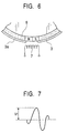
- the induced voltage includes a sub-peak as shown in Fig. 7, which does not arise in the conventional case in which the Hall devices 107 are used.
- This sub-peak impedes accurate detection of the index position.
- the sub-peak is excluded by masking as described below.
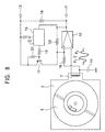
- Fig. 8 shows an index signal generating circuit which excludes the sub-peak and generates the index signal
- Fig. 9 shows waveforms of voltages obtained at certain points in the circuit.
- the index signal generating circuit includes a comparator 12 which compares the induced voltage obtained from the inductor 7 and a mask signal obtained from a transistor 11, a power supply terminal 13, a bias power supply 14, a monostable multivibrator (mask-voltage generator) 15 which outputs a square wave signal for a predetermined time period after receiving the result of the comparison from the comparator 12, and the transistor 11 which switches the square wave signal obtained from the monostable multivibrator 15 to generate the mask signal.
- a comparator 12 which compares the induced voltage obtained from the inductor 7 and a mask signal obtained from a transistor 11, a power supply terminal 13, a bias power supply 14, a monostable multivibrator (mask-voltage generator) 15 which outputs a square wave signal for a predetermined time period after receiving the result of the
- a recursive resistor 12f is connected between the non-inverting input terminal and the output terminal of the comparator 12.
- the non-inverting input of the comparator 12 is connected to one end of the inductor 7, and the output terminal of the comparator 12 is connected to a signal output terminal 17 and to the power supply terminal 13 via a resistor 18.
- the bias power supply 14 is connected between the other end of the inductor 7 and the ground.
- the input terminal of the monostable multivibrator 15 is connected to the output terminal of the comparator 12, and the output terminal of the monostable multivibrator 15 is connected to base of the transistor 11 via a resistor 19.
- a resistor 20 is connected between the base and the emitter of the transistor 11.
- the collector of the transistor 11 is connected to the non-inverting input terminal of the comparator 12, and the emitter of the transistor 11 is connected to the power supply terminal 13.
- the inductor 7 detects the periodic proximity of the outwardly facing part of the rotor 8 by using the time variation of the magnetic flux, and outputs the magnetic flux detection signal.
- the detection output representing the induced voltage has two positive-polarity peaks, P 1 and P 2 .
- the comparator 12 compares the voltage input (first input) obtained from the non-inverting input terminal and the magnetic flux detection signal (second input) obtained from the inverting input terminal. Referring to Fig. 9A, the first input is shown by the dotted-chain line, and the second input is shown by the solid line.
- the comparator 12 outputs a negative-polarity output which falls when the second input voltage exceeds the first input voltage, and rises when the first input voltage exceeds the second input voltage. The output from the comparator is supplied to the signal output terminal 17.
- the monostable multivibrator 15 reacts to the rising edge of the output from the comparator, and generates a negative-polarity square wave signal for a predetermined time period.
- the transistor 11 is ON during the time period in which the square wave signal is supplied, so as to input high voltage V H to the non-inverting input terminal of the comparator 12, as shown by the dotted-chain line in Fig. 9A.
- the high voltage V H is approximately the same as the power supply voltage V cc .
- the first input voltage is sufficiently higher than the second input voltage, so that the second peak P 2 is masked.
- the mask signal is not supplied to the comparator 12 from the transistor 11, so that the above-described comparison is performed between the first input signal and the second input signal.
- the voltage V 2 which is the magnetic flux detection output while the magnetic flux is not detected by the inductor 7, must be lower than the voltage V 1 supplied to the non-inverting input of the comparator 12.
- the positive-polarity peak P 1 which is obtained when the inductor 7 detects the magnetic flux must be higher than the voltage V 1 .
- the comparator output includes the falling edge at the time when the second input voltage exceeds the first input voltage, and also includes the rising edge at the same time when the first input voltage exceeds the second input voltage.
- the first input exceeds the second input voltage at the time when the induced voltage obtained by the inductor 7 is approximately zero.
- the index signal is generated by using the rising edge of the comparator output.
- the index signal provides a pulse at the time when the comparator output provides the rising edge, that is, the time when the magnetic flux detection output is approximately zero. Since the amplitude of the magnetic flux detection signal is completely free from temperature variation, time intervals between the pulses of the index signal are not affected by temperature variation. In addition, even when the magnetic flux detection signal obtained from the inductor 7 includes two peaks P 1 and P 2 of the same polarity and approximately the same magnitude, the index signal provides a pulse at precise times since one of the peaks, P 2 , is masked by applying the mask signal.
Landscapes
- Brushless Motors (AREA)
- Permanent Magnet Type Synchronous Machine (AREA)
- Rotational Drive Of Disk (AREA)
Abstract
Description
Claims (4)
- An index position detector for a spindle motor, comprising:a rotor magnet which is provided to an inner surface of a flange portion of a rotor yoke with which the spindle motor is constructed;a window portion formed in said flange portion in a manner such that a part of said rotor magnet faces outwardly; andan inductor which is disposed in a stator section so as to oppose the periphery of said flange portion and which detects a magnetic flux of said rotor magnet via said window portion.
- An index position detector for a spindle motor, according to Claim 1, wherein said inductor is disposed so as to oppose the periphery of said flange portion in a' manner such that the central axis of a coil contained in said inductor is approximately parallel to the tangential direction of the periphery of said rotor yoke.
- A motor apparatus comprising:a circuit board which is disposed above a mount;a rotor yoke which is rotatably supported by said mount;a rotor magnet which is provided to an inner surface of a flange portion of said rotor yoke;stator coils which are disposed between said rotor yoke and said mount and which are arranged radially around the rotational center of said rotor yoke;lands which are provided on said circuit board at positions between said stator coils to connect coil terminals of said stator coils; andan inductor which is mounted on said circuit board so as to oppose the periphery of said flange portion and which detects a magnetic flux of said rotor magnet via said window portion,wherein said circuit board is formed so as not to extend over one side of the mount relative to said rotational center of said rotor yoke.
- A motor apparatus according to Claim 3, wherein said lands on which said coil terminals of said stator coils are soldered are provided on said circuit board on which said inductor is mounted, and wherein the area of said circuit board is smaller than half the area of said mount.
Applications Claiming Priority (2)
| Application Number | Priority Date | Filing Date | Title |
|---|---|---|---|
| JP2000044891A JP2001236721A (en) | 2000-02-22 | 2000-02-22 | Index position detector of spindle motor and motor device having the same |
| JP2000044891 | 2000-02-22 |
Publications (2)
| Publication Number | Publication Date |
|---|---|
| EP1128380A2 true EP1128380A2 (en) | 2001-08-29 |
| EP1128380A3 EP1128380A3 (en) | 2003-03-12 |
Family
ID=18567582
Family Applications (1)
| Application Number | Title | Priority Date | Filing Date |
|---|---|---|---|
| EP00310973A Withdrawn EP1128380A3 (en) | 2000-02-22 | 2000-12-08 | Index position detector for spindle motor and motor apparatus including the same |
Country Status (4)
| Country | Link |
|---|---|
| US (1) | US6603304B2 (en) |
| EP (1) | EP1128380A3 (en) |
| JP (1) | JP2001236721A (en) |
| CN (1) | CN1179344C (en) |
Families Citing this family (6)
| Publication number | Priority date | Publication date | Assignee | Title |
|---|---|---|---|---|
| JP2003059254A (en) * | 2001-08-22 | 2003-02-28 | Mitsumi Electric Co Ltd | Flexible disk drive |
| JP2003134770A (en) * | 2001-10-23 | 2003-05-09 | Mitsumi Electric Co Ltd | Flexible disk drive |
| JP2004364354A (en) * | 2003-06-02 | 2004-12-24 | Mitsumi Electric Co Ltd | Disk index signal generation method and disk drive device |
| JP5101309B2 (en) * | 2008-01-15 | 2012-12-19 | 三菱重工業株式会社 | MOTOR POSITION DETECTION METHOD, MOTOR DRIVE DEVICE, AND PUMP |
| CN202840736U (en) | 2012-08-31 | 2013-03-27 | 日本电产株式会社 | Motor used for driving color wheel and digital optical processing projector comprising motor used for driving color wheel |
| JP6514970B2 (en) * | 2015-06-25 | 2019-05-15 | 株式会社マキタ | Electric tool |
Family Cites Families (8)
| Publication number | Priority date | Publication date | Assignee | Title |
|---|---|---|---|---|
| US3483457A (en) * | 1967-06-21 | 1969-12-09 | Massachusetts Inst Technology | Electronically commutated permanent magnet torque motor |
| US4295085A (en) * | 1979-05-25 | 1981-10-13 | General Electric Company | Phase lock loop commutation position control and method |
| JP2546085B2 (en) * | 1991-06-07 | 1996-10-23 | ティアック株式会社 | Disk unit |
| US5408153A (en) * | 1991-07-05 | 1995-04-18 | Canon Denshi Kabushiki Kaisha | Index position detecting apparatus for an electromagnetic rotary machine |
| JP2854519B2 (en) | 1994-02-07 | 1999-02-03 | 株式会社三協精機製作所 | Brushless motor |
| JP3124678B2 (en) * | 1994-03-16 | 2001-01-15 | アルプス電気株式会社 | motor |
| JP3151758B2 (en) * | 1995-06-23 | 2001-04-03 | ソニー株式会社 | Sensorless motor drive circuit |
| JPH09326159A (en) * | 1996-06-04 | 1997-12-16 | Alps Electric Co Ltd | Index signal forming circuit |
-
2000
- 2000-02-22 JP JP2000044891A patent/JP2001236721A/en not_active Withdrawn
- 2000-12-08 EP EP00310973A patent/EP1128380A3/en not_active Withdrawn
-
2001
- 2001-02-13 CN CNB011018887A patent/CN1179344C/en not_active Expired - Fee Related
- 2001-02-21 US US09/790,226 patent/US6603304B2/en not_active Expired - Fee Related
Also Published As
| Publication number | Publication date |
|---|---|
| CN1179344C (en) | 2004-12-08 |
| US6603304B2 (en) | 2003-08-05 |
| EP1128380A3 (en) | 2003-03-12 |
| JP2001236721A (en) | 2001-08-31 |
| CN1310444A (en) | 2001-08-29 |
| US20020059038A1 (en) | 2002-05-16 |
Similar Documents
| Publication | Publication Date | Title |
|---|---|---|
| US4093897A (en) | Electric motor | |
| US4578606A (en) | Brushless DC electric motor and tachogenerator assembly | |
| JPS60261350A (en) | Angular position detector of rotary electronic machine rotorby electronic switching | |
| US4455516A (en) | Brushless motor | |
| GB1563228A (en) | Electric motors | |
| JPH11318067A (en) | Electronic commutation type motor | |
| US6476528B2 (en) | Spindle motor rotor, index signal output device, and floppy disk drive having the same | |
| US4737675A (en) | Brushless motor with center leads for preventing signal distortion | |
| US6603304B2 (en) | Index position detector for spindle motor and motor apparatus including the same | |
| US6697215B2 (en) | Index signal output device and floppy disk drive | |
| JPS6145468A (en) | Apparatus and circuit for driving signal processor | |
| JPH04362566A (en) | Disk device | |
| US5319271A (en) | Pulse signal generating device | |
| JPH1141897A (en) | Motor with rotation speed detection means | |
| JP2536854B2 (en) | Method and apparatus for generating rotation speed information for controlling rotation speed of brushless DC motor | |
| JPH0828033B2 (en) | Flexible disk drive device | |
| JPS61280753A (en) | Variable speed permanent magnet motor | |
| JPS581896Y2 (en) | Turntable drive device | |
| JP4418045B2 (en) | Electric motor | |
| JP2603170Y2 (en) | Disk rotation drive | |
| JP2629656B2 (en) | Rotational position detector | |
| JPH0260449A (en) | Motor for media drive device | |
| KR900007228Y1 (en) | Motor detection device | |
| KR960009804Y1 (en) | Rotating frequency generator of small precision motor | |
| JPS6260457A (en) | Flat type motor |
Legal Events
| Date | Code | Title | Description |
|---|---|---|---|
| PUAI | Public reference made under article 153(3) epc to a published international application that has entered the european phase |
Free format text: ORIGINAL CODE: 0009012 |
|
| AK | Designated contracting states |
Kind code of ref document: A2 Designated state(s): AT BE CH CY DE DK ES FI FR GB GR IE IT LI LU MC NL PT SE TR |
|
| AX | Request for extension of the european patent |
Free format text: AL;LT;LV;MK;RO;SI |
|
| PUAL | Search report despatched |
Free format text: ORIGINAL CODE: 0009013 |
|
| AK | Designated contracting states |
Kind code of ref document: A3 Designated state(s): AT BE CH CY DE DK ES FI FR GB GR IE IT LI LU MC NL PT SE TR Designated state(s): AT BE CH CY DE DK ES FI FR GB GR IE IT LI LU MC NL PT SE TR |
|
| AX | Request for extension of the european patent |
Extension state: AL LT LV MK RO SI |
|
| 17P | Request for examination filed |
Effective date: 20030502 |
|
| AKX | Designation fees paid |
Designated state(s): DE FR GB |
|
| 17Q | First examination report despatched |
Effective date: 20040317 |
|
| STAA | Information on the status of an ep patent application or granted ep patent |
Free format text: STATUS: THE APPLICATION IS DEEMED TO BE WITHDRAWN |
|
| 18D | Application deemed to be withdrawn |
Effective date: 20050628 |