EP1128371A1 - Procédé et dispositif de contrôle du positionnement d'un faisceau optique incident sur une piste d'un support mobile d'informationS contenues dans ladite piste, en particulier un disque numérique multi-fonctions - Google Patents
Procédé et dispositif de contrôle du positionnement d'un faisceau optique incident sur une piste d'un support mobile d'informationS contenues dans ladite piste, en particulier un disque numérique multi-fonctions Download PDFInfo
- Publication number
- EP1128371A1 EP1128371A1 EP01400389A EP01400389A EP1128371A1 EP 1128371 A1 EP1128371 A1 EP 1128371A1 EP 01400389 A EP01400389 A EP 01400389A EP 01400389 A EP01400389 A EP 01400389A EP 1128371 A1 EP1128371 A1 EP 1128371A1
- Authority
- EP
- European Patent Office
- Prior art keywords
- sampled
- time difference
- signal
- signals
- inter
- Prior art date
- Legal status (The legal status is an assumption and is not a legal conclusion. Google has not performed a legal analysis and makes no representation as to the accuracy of the status listed.)
- Granted
Links
- 230000003287 optical effect Effects 0.000 title claims abstract description 16
- 238000000034 method Methods 0.000 title claims description 12
- 238000005070 sampling Methods 0.000 claims abstract description 23
- 238000005314 correlation function Methods 0.000 claims description 33
- 230000007704 transition Effects 0.000 claims description 27
- 238000012545 processing Methods 0.000 claims description 13
- 238000012805 post-processing Methods 0.000 claims description 11
- 102100021908 3-mercaptopyruvate sulfurtransferase Human genes 0.000 claims description 7
- 101000753843 Homo sapiens 3-mercaptopyruvate sulfurtransferase Proteins 0.000 claims description 7
- 238000001514 detection method Methods 0.000 claims description 6
- 238000007781 pre-processing Methods 0.000 claims description 3
- 238000004364 calculation method Methods 0.000 claims description 2
- 101100488882 Saccharomyces cerevisiae (strain ATCC 204508 / S288c) YPL080C gene Proteins 0.000 claims 1
- 101100278987 Arabidopsis thaliana ECH2 gene Proteins 0.000 description 8
- 230000006870 function Effects 0.000 description 6
- 235000021183 entrée Nutrition 0.000 description 3
- 230000010354 integration Effects 0.000 description 3
- 230000008569 process Effects 0.000 description 3
- 102100040515 Delta(3,5)-Delta(2,4)-dienoyl-CoA isomerase, mitochondrial Human genes 0.000 description 2
- 101000966982 Homo sapiens Delta(3,5)-Delta(2,4)-dienoyl-CoA isomerase, mitochondrial Proteins 0.000 description 2
- 240000008042 Zea mays Species 0.000 description 2
- 238000001914 filtration Methods 0.000 description 2
- 230000002123 temporal effect Effects 0.000 description 2
- 230000008859 change Effects 0.000 description 1
- 230000003111 delayed effect Effects 0.000 description 1
- 238000011161 development Methods 0.000 description 1
- 238000010586 diagram Methods 0.000 description 1
- 238000005516 engineering process Methods 0.000 description 1
- 238000009432 framing Methods 0.000 description 1
- 238000004519 manufacturing process Methods 0.000 description 1
- 238000005259 measurement Methods 0.000 description 1
- 230000004048 modification Effects 0.000 description 1
- 238000012986 modification Methods 0.000 description 1
- 230000004044 response Effects 0.000 description 1
- 230000002441 reversible effect Effects 0.000 description 1
Images


Classifications
-
- G—PHYSICS
- G11—INFORMATION STORAGE
- G11B—INFORMATION STORAGE BASED ON RELATIVE MOVEMENT BETWEEN RECORD CARRIER AND TRANSDUCER
- G11B7/00—Recording or reproducing by optical means, e.g. recording using a thermal beam of optical radiation by modifying optical properties or the physical structure, reproducing using an optical beam at lower power by sensing optical properties; Record carriers therefor
- G11B7/08—Disposition or mounting of heads or light sources relatively to record carriers
- G11B7/09—Disposition or mounting of heads or light sources relatively to record carriers with provision for moving the light beam or focus plane for the purpose of maintaining alignment of the light beam relative to the record carrier during transducing operation, e.g. to compensate for surface irregularities of the latter or for track following
- G11B7/0901—Disposition or mounting of heads or light sources relatively to record carriers with provision for moving the light beam or focus plane for the purpose of maintaining alignment of the light beam relative to the record carrier during transducing operation, e.g. to compensate for surface irregularities of the latter or for track following for track following only
Definitions
- the invention relates to controlling the positioning of a incident beam on a track of a support, mobile in rotation, of information contained in said track, and more particularly the control and determination of the beam positioning error incident to the runway.
- the invention applies advantageously but not limited to digital discs, in particular discs digital multifunction (DVD: "Digital Versatile disc” in language English) storing compressed image data.
- DVD digital multifunction
- a digital disc has a single spiral track whose relief is representative of the binary information stored on the track of the disk. It is illuminated by an incident optical beam, for example a spot laser, the disc track and several photodetectors, for example four, detect the reflections of the light beam on the disc.
- the sensor optical formed by photodetectors then delivers four signals elementary respectively delivered by the four photodetectors, as well as a global signal, or useful signal, equal to the sum of the four elementary signals, useful signal from which the information is extracted binaries read on the track.
- Enslavement of the optical beam on the disc track mobile in rotation is carried out exclusively from the four signals elementary delivered by photodetectors. More specifically, we sum the signals in pairs so as to form two signals which are equalizes in an analog equalizer before formatting them, by comparison with a threshold, in two comparators. The two signals thus formed are mutually out of phase if the laser spot is not located not on the track. We then detect the phase difference between these two signals (phase difference which is actually a time difference between these two signals), time difference which corresponds to the error of beam positioning relative to the runway. This error of positioning is then conventionally used in a loop control system to modify the incident optical system and bring back and slave the optical beam on the runway.
- Such a device of the prior art comprises a large number of analog components, which is relatively disadvantageous by one point of congestion view. Furthermore, when technology evolves, the modification and production of new device components require a significant time of conception and realization.
- mirror signal which is calculated at from the lower amplitude of the wanted signal. More specifically, we compares the low envelope of the useful signal to a threshold, which provides said mirror signal. And, this mirror signal thus obtained is always in quadrature phase with respect to a binary signal representative of the crossing a portion of the runway. Determining the sign of the phase difference between the mirror signal and the runway crossing signal, provides the direction of crossing the track.
- the invention aims to provide a solution to these problems and has in particular to improve the accuracy in determining positioning error, while avoiding in particular analog equalizers.
- the invention also makes it possible to determine the direction of crossing of a section of track without requiring the creation of a mirror signal.
- the invention therefore provides a control of the positioning of a incident optical beam on a track of a mobile information carrier contained in said track, radically different from that proposed until then, and in particular using an inter-correlation function between two mutually out of phase sampled signals.
- the search for maximum of the inter-correlation function will provide, at all times current, the current value of the phase difference between the two signals, i.e. the current value of the time difference between these two signals.
- the invention proposes a method for controlling the positioning of an incident optical beam on a track of a support of information contained in said track and mobile in rotation, method in which the beam reflected by the disc is captured by means of a optical sensor comprising several photodetectors delivering respectively several elementary signals, and the error is determined beam positioning relative to the track from signals elementary.
- sampled signals which we here denotes sampled "secondary signals”, whose time difference mutual is representative of the beam positioning error by compared to the runway. And, we determine, at the sampling frequency, the successive current values of said mutual time difference by searching, at the sampling frequency, the successive current maxima of the inter-correlation function between the two secondary signals sampled.
- the process according to the invention is an optimum process essentially arithmetic, which leads to improved performance and which, moreover, is less sensitive to noise.
- the function of inter-correlation operates on all the sampled signals and not not only on the transitions of these sampled signals (a transition being the crossing by a predetermined threshold, for example the value zero, of the signal sampled), as has already been described in particular in French patent application No. 9903237 in the name of the Applicant.
- the process according to the invention therefore also overcomes the problem of estimating the time instants of these transitions.
- Each reference time difference is advantageously a integer multiple of a basic time difference, the value of which depends on the frequency band occupied by the two secondary signals sampled.
- one of the reference time differences is zero and the others are two to two equals and of opposite sign.
- the frequency band occupied by the two signals secondary is proportional to the speed of rotation of the portion of track read. So this basic time difference is not the same for 1x or 16x speeds (a rotation speed of 1x corresponding to 4 m / s). Generally, the choice of the value of this time difference of basis is not critical to the invention, but inappropriate value may lead to degraded performance. Those skilled in the art will be able to adjust the value of this basic time difference, as well as the number of samples of the inter-correlation function, so that we can cover the whole possible time differences between the two sampled signals and for also be able to obtain an inter-correlation function which is not under or oversampled.
- the number of reference time differences is five and the basic time difference is advantageously chosen to be less than the inverse of the width of the strip frequencies.
- Determining the value of the corresponding time difference at a current maximum includes, in one embodiment of the invention, the selection, among the samples of the inter-correlation function, the one with the highest value and the two samples framing it. This determination also includes an interpolation parabolic between the three selected values and the calculation of the ratio between two factors resulting from this parabolic interpolation.
- this mode of implementation using parabolic interpolation requires at least three values of inter-correlation function. That said, in the event that only three cross-correlation function values are used (corresponding to a set of three reference time differences), a choice should be made value of the basic time difference large enough to be able to determine the maximum of this inter-correlation function. In the case where five samples are used, the value of the basic time difference may be smaller.
- the invention also relates to a device for controlling the positioning of an incident optical beam on a track of a support of information contained in said track and mobile in rotation, this device comprising a sensor capable of picking up the beam reflected by the disk and comprising several photodetectors.
- the device includes also control means capable of determining the error of beam positioning relative to the track from signals elementary respectively delivered by the photodetectors.
- the processing means are then able to search for each maximum current of the inter-correlation function from each set samples stored in the storage medium, and determining the value of the time difference corresponding to this current maximum, this value thus determined providing the current value of the time difference between the sampled secondary signals.
- the means of processing include selection means capable of selecting, from the samples stored in the storage means, the one having the most great value and the two samples surrounding it.
- the means of treatment also include interpolation means suitable for perform a parabolic interpolation between the three values selected and calculate the ratio between two factors resulting from this parabolic interpolation, this ratio providing the current value of the mutual time difference between the two secondary signals sampled.
- the device according to the invention also comprises advantageously post-processing means able to develop from successive report scanners, a first output signal binary representative of the possible crossing of the track by the signal incident, and to develop from the numerators and denominators of successive reports, a second binary output signal representative of the direction of crossing of the runway by the incident signal.
- a subject of the invention is also a disc player.
- digital multifunction incorporating a control device such as defined above.
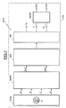
- the reference DCP more particularly designates a positioning control device according to the invention, comprising header a PHD sensor composed of four photodetectors A, B, C, D.
- a laser diode emits a laser beam which is directed towards the face of the disc on which the track containing the information is engraved, by in particular through a separating plate and an optical system classic.
- the beam reflected by the rotating disc then crosses into the other direction the separating plate and is picked up by the four photodetectors A, B, C, D which are all four in a plane parallel to the plane of the disk.
- Each photodetector delivers a signal that has been referenced, to for the sake of simplification, by the same letter as that assigned to photodetectors.
- These elementary signals A, B, C, D are then processed in MPRT pre-processing means, essentially comprising summers and analog to digital converters.
- references A + C and B + D thus designate two secondary signals, sampled after passing through two analog-to-digital converters controlled by a clock signal
- the frequency of sampling Fe is for example equal to 120 MHz corresponding to a sampling period of the order 8.33 ns.
- each sample of a secondary signal is a signed integer represented on 7 bits.
- MT processing means will determine the values current or successive of said mutual time difference TE by seeking, at the sampling frequency, the successive current maxima of the inter-correlation function between the two secondary signals sampled.
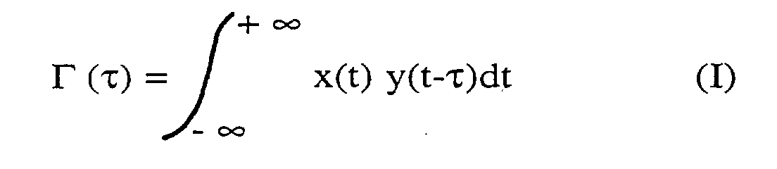
- the inter-correlation function ⁇ has a maximum for the value of ⁇ equal to the value of the time difference (delay) between the signals x and y.
- the delay (deviation mutual time) between the sampled signals A + C on the one hand, and B + D on the other hand is variable.
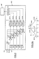
- the MIC inter-correlation means will then estimate, at the sampling frequency, i.e. for each pair samples of signals A + C and B + D present at the input of the means MIC inter-correlation, the inter-correlation function ⁇ ( ⁇ ) for a game predetermined reference time difference -2D ', -D', 0, D 'and 2D'.
- the processing means MT then go, for each set ECH1-ECH5 samples, determine the maximum of this function of inter-correlation by performing as will be seen in more detail below a parabolic interpolation, the value of the time difference dT of this maximum current MAX (counted in figure 2a from the deviation reference time zero) is then representative of the current value of the mutual time difference between the two sampled signals A + C and B + D. These operations are repeated when the samples appear according to signals A + C and B + D. So we get, at the frequency sampling (i.e. every 8.33 ns in this case), successive values of the mutual time difference TE between the two signals sampled A + C and B + D.
- the means inter-correlation MIC have two inputs E1, E2 to receive respectively the two sampled secondary signals A + C and B + D.
- the intercorrelation means here comprise five multipliers M1-M5 each having a first input el and a second input e2.
- the delay means comprise a chain of four elements delay ER1-ER4, each defining a delay value equal to the deviation basic temporal D '.
- the delay means also include a delay element additional ERS defining a 2D 'delay value equal to double of the basic time difference.
- the value D 'of the basic time difference is equal to one whole number of sampling periods. For example, for a rotation speed equal to 2x, and a frequency band occupied by the sampled signals equal to 9 MHz, we can choose D 'equal to the reverse double the width of the frequency band, i.e. 1/18 MHz, i.e. of the order of 55 ns, which corresponds to a basic delay equal to 6 samples (for a sampling frequency of 120 MHz).
- each delay element ERi can be consisting of 12 flip-flops in series clocked by the signal sampling, while the ERS element may consist of 24 flip-flops in series clocked by the sampling clock signal.
- the first input el of each multiplier is connected to the first input E1 of the inter-correlation means by means of the additional delay element ERS.
- the second entry e2 of another multiplier (here the multiplier M5) is connected to the other end EX2 of the chain of delay.
- the respective second entries e2 of the other three multipliers M2, M3 and M4 are respectively connected to the three intermediate points EI2, EI3 and EI4 of the chain of delay elements.
- the respective outputs of the five M1-M5 multipliers are connected to five LPF1-LPF5 digital low-pass filters, of structure known per se. All these low-pass filters realize the present integration in the formula for the inter-correlation function.
- Each low pass filter here is a first order recursive filter.
- the parameter N defines the filter cutoff frequency, i.e. the integration time of the correlator. In this case, the value 64 has been chosen for N so to provide a cut-off frequency of 300 kHz.
- Filter outputs low pass provide the five samples ECH1-ECH5 of the function of inter-correlation. These samples are stored in a means of RS storage composed for example of five scales. In the example described, each sample is a 14-bit word.
- selection means MS able to select, from among samples stored in the RS storage means, that (referenced b in Figure 2a) with the highest value and the two samples the frame (respectively referenced a and c in FIG. 2a).
- ECH4 is greater than ECH3 and if ECH4 is greater than ECH2 (step 40), then the sample with the largest value (b) is the ECH4 sample and the two samples surrounding it are samples ECH3 and ECH5.
- the sample ECH3 is greater than or equal to the ECH2 sample and also greater than or equal to the ECH4 sample (step 41), then b is equal to ECH3, a is equal to ECH2 and c is equal to ECH4.
- sample ECH2 is strictly greater than sample ECH3 and to sample ECH4 (step 42), then b is equal to ECH2, a is equal to ECH1 and c is equal to ECH3.
- the MIP parabolic interpolation means will then use the values a, b and c to perform a parabolic interpolation between these three samples, so as to determine the MAX maximum of the function of inter-correlation and consequently the time difference dT separating this maximum of sample b ( Figure 2a).
- the sample of the highest value inter-correlation function i.e. sample b
- the difference mutual time T between the two sampled signals A + C and B + D is then equal to dT.
- sample b corresponds to the difference reference time equal to -D 'or + D'
- the value D ' has been chosen so that, whatever the difference mutual time between the secondary signals A + C and B + D, we have always the corresponding sample b, i.e. at the reference time difference -D ', either to + D', or to 0.
- T M + (ca) / (2 (2b-ac))
- M denotes an integer capable of taking the value -1, 0 or +1.
- This value -1, 0 or +1 is defined by the selection means MS. So, if we refer again to Figure 4, we see that if sample b is sample ECH4, M will take the value 1. On the other hand, if sample b corresponds to sample ECH3, M will take the value 0, and if sample b corresponds to sample ECH2, M will take the value -1.
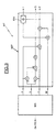
- the material structure of the MIP interpolation means can be produced as illustrated in FIG. 3, based on adders and multipliers. These MIP means can thus be produced in a way software within a microprocessor or in the form of a circuit integrated.
- the MIP means deliver a value of signal P and a value of signal Q. These two values are divided into a divider DIV, so as to provide the desired mutual time difference T. This division is advantageously carried out for reasons of precision, in "floating binary".
- the positioning error TE is then equal to the product of the time difference T by the estimated speed of rotation.
- This speed of estimated rotation is for example from counting the number of zero crossings of the global signal A + B + C + D during a certain number samples, typically 88,000 to 120 MHz.
- This estimate of the rotation speed also corrects the value of the deviation basic temporal D '.
- the successive samples of the P numerators and denominators Q will respectively form a first input signal sampled P and a second sampled input signal Q.
- the MPST post-processing means will then develop from these two sampled input signals a first binary output signal TZC, representative of the possible crossing of the runway portion by the incident signal and a second representative DIR binary output signal the direction of crossing of the runway portion by the incident signal.
- the signal P is equal to zero each time the error of TE positioning is zero and can therefore be used as a signal TZC.
- the Q signal which directly depends on the width of the frequencies, is maximum when the laser spot is on the track and minimum when the laser spot is located between two portions of the track. He can therefore act as a "mirror" signal.
- the invention is remarkable here in the sense that the P and Q signals are always quadrature, so that they have the same properties as the TZC and "mirror" signals used in the prior art.
- the signals sampled P and Q come from the same processing block, i.e. MIP interpolation means. They can therefore undergo identical filtering without risk of measurement disturbance.
- the signal P will be used to set the TZC signal. More specifically, the detection of each transition TR of signal P with respect to a predetermined threshold, for example the value zero, will be representative of the possible crossing of a section of runway by the incident signal. So the TZC signal will be a sampled signal binary alternately taking the values +1 or 0 at each crossing of the threshold by the signal P. Materially, the signal TZC is obtained, as illustrated in FIG. 5, by comparison of the signal P in a CMH hysteresis comparator of known structure, the value of the hysteresis Hyst being taken for example equal to 1/8 of the amplitude of the signal P.
- a predetermined threshold for example the value zero
- q denotes the amplitude of the signal Q at each current transition TR of signal P
- qp denotes the amplitude of this signal Q at the previous transition TR of signal P.
- the DIR signal will take either the value 0 or the value 1, in depending on the direction of crossing of the track portion.
- the post-processing means include a first input to receive the first sampled input signal P and a second input to receive the second input signal sampled Q.
- the MPST post-processing means also include transition detection means, namely the hysteresis comparator CMH, connected to the first input, and able to detect each transition TR of the input signal P and to deliver the first binary output signal TZC.
- transition detection means namely the hysteresis comparator CMH
- These means also include a sample and hold device ECB of known structure, connected to the second input and by means CMH transition detection. This sampler is able to store the amplitude of the second input signal Q at each current transition detected TR of the first input signal P.
- the MPST means also include a flip-flop BS, controlled by the transitions TR of the first input signal P, and connected to the output of the ECB sampler-blocker. This rocker is intended to memorize the amplitude of the second input signal Q at the previous transition of the first input signal.
- an LG logic block generates the second output signal binary DIR.
- This LG logic block includes a CMP comparator whose two inputs are respectively connected to the output of the BS flip-flop and to the ECB sampler-blocker output.
- LG logic block has also an exclusive OR logic gate referenced PL including one input is connected to the output of the CMP comparator and the other input of which receives the first TZC output signal. The output of the logic gate PL delivers the second binary DIR output signal.
- two low-pass filters LPF8 and LPF9 of the infinite impulse response intended to filter the P and Q signals before their treatment are advantageously adjusted according to the frequency of crossing portions of tracks which is a signal delivered by the logic block LG.
- a cut-off frequency of the order 100 kHz for low-pass filters when the frequency of crossing of track portions is less than 50 kHz (start of carriage movement).
- a cutoff frequency of the order of 600 kHz for low-pass filters when the frequency of crossing of track portions is greater than 50 kHz.
- the system according to the invention also makes it possible to better control the detection of transitions when you start moving the carriage and allow also to easily determine the changes in direction of crossing portions of tracks. It suffices to memorize no only the value of the amplitude of the signal Q at the previous transition, but also that at the transition preceding this preceding transition. If qpp designates the amplitude of the signal Q two transitions before a current transition, then any change in direction of crossing will be detected each time the absolute value of the difference (q-qp) will be less than the absolute value of the difference (q-qpp).
Landscapes
- Optical Recording Or Reproduction (AREA)
- Moving Of Head For Track Selection And Changing (AREA)
- Moving Of The Head For Recording And Reproducing By Optical Means (AREA)
Abstract
Description
- des moyens de prétraitement aptes à élaborer à partir des signaux élémentaires, deux signaux secondaires échantillonnés par un signal d'horloge d'échantillonnage, l'écart temporel mutuel entre les deux signaux secondaires échantillonnés étant représentatif de l'erreur de positionnement du faisceau par rapport à la piste,
- des moyens d'inter-corrélation aptes à effectuer, à la fréquence du signal d'échantillonnage, la fonction d'inter-corrélation entre les deux signaux secondaires échantillonnés, et
- des moyens de traitement aptes à déterminer les valeurs courantes successives dudit écart temporel mutuel en recherchant, à la fréquence d'échantillonnage, les maxima courants successifs de la fonction d'inter-corrélation entre les deux signaux secondaires échantillonnés. Selon un mode de réalisation de l'invention, les moyens d'inter-corrélation comportent
- deux entrées pour recevoir respectivement les deux signaux secondaires échantillonnés;
- un jeu de multiplieurs, connectés aux deux entrées par des moyens de retard, et délivrant respectivement un jeu de signaux intermédiaires échantillonnés correspondant respectivement aux produits des signaux secondaires échantillonnés mutuellement décalés temporellement par des écarts temporels de référence;
- un jeu de filtres passe-bas respectivement connectés aux sorties des différents multiplieurs; et
- un moyen de stockage, connecté aux sorties des filtres passe-bas et apte à stocker les jeux successifs d'échantillons de la fonction d'inter-corrélation respectivement associés aux différents écarts temporels de référence.
- la figure 1 représente très schématiquement un synoptique d'un dispositif de contrôle selon l'invention, incorporé dans un lecteur de disque DVD;
- la figure 2 illustre, plus en détail mais toujours schématiquement, l'architecture interne des moyens d'inter-corrélation du dispositif de la figure 1;
- la figure 2a représente une fonction d'inter-corrélation échantillonnée réalisée par les moyens de la figure 2;
- la figure 3 illustre plus en détail mais toujours schématiquement, l'architecture interne des moyens de traitement des dispositifs de la figure 1;
- la figure 4 représente un organigramme illustrant la sélection opérée par les moyens de sélection incorporés dans les moyens de traitement du dispositif selon l'invention;
- la figure 5 illustre plus en détail l'architecture interne de moyens de post-traitement du dispositif selon l'invention; et
- la figure 5a représente les signaux d'entrée traités par ces moyens de post-traitement ainsi que l'un des signaux de sortie délivré par ces moyens de post-traitement.
Claims (13)
- Procédé de contrôle du positionnement d'un faiceau optique incident sur une piste d'un support, mobile en rotation, d'informations contenues dans ladite piste,dans lequel on capte le faisceau réfléchi par le disque au moyen d'un capteur optique comportant plusieurs photodétecteurs (PHD) délivrant respectivement plusieurs signaux élémentaires (A,B,C,D), et on détermine l'erreur de positionnement (TE) du faisceau par rapport à la piste à partir des signaux élémentaires, caractérisé par le fait qu'on élabore à partir des signaux élémentaires, deux signaux secondaires (A+C; B+D) échantillonnés dont l'écart temporel mutuel (T) est représentatif de l'erreur de positionnement (TE) du faisceau par rapport à la piste, et on détermine, à la fréquence d'échantillonnage, les valeurs courantes successives dudit écart temporel mutuel (T) en recherchant, à la fréquence d'échantillonnage, les maxima courants successifs (MAX) de la fonction d'inter-corrélation entré les deux signaux secondaires échantillonnés.
- Procédé selon la revendication 1, caractérisé par le fait qu'on recherche chaque maximum courant (MAX) de la fonction d'inter-corrélation à partir d'un jeu d'échantillons (ECH1-ECH5) de cette fonction d'inter-corrélation correspondant respectivement à un jeu prédéterminé de valeurs d'écarts temporels de référence (-2D', ..., 2D'), et on détermine la valeur de l'écart temporel (T) correspondant à ce maximum courant, cette valeur ainsi déterminée fournissant la valeur courante de l'écart temporel mutuel (T) entre les deux signaux secondaires échantillonnés.
- Procédé selon la revendication 2, caractérisé par le fait que chaque écart temporel de référence est un multiple entier d'un écart temporel de base (D'), l'un des écarts temporels de référence étant nul et les autres étant deux à deux égaux et de signe opposé, et par le fait que la valeur de l'écart temporel de base (D') dépend de la bande de fréquences occupée par les deux signaux secondaires échantillonnés.
- Procédé selon la revendication 3, caractérisé par le fait que le nombre d'écarts temporels de référence est égal à cinq, et par le fait que la valeur de l'écart temporel de base (D') est inférieure à l'inverse de la largeur de la bande de fréquences.
- Procédé selon l'une des revendications 2 à 4, caractérisé par le fait que la détermination de la valeur de l'écart temporel (T) correspondant à un maximum courant (MAX) comporte la sélection, parmi les échantillons de la fonction d'inter-corrélation, de celui ayant la plus grande valeur (b) et des deux échantillons (a, c) l'encadrant, une interpolation parabolique entre les trois valeurs sélectionnées et le calcul du rapport (P/Q) entre deux facteurs résultant de cette interpolation parabolique.
- Procédé selon la revendication 5, caractérisé par le fait qu'on élabore à partir des numérateurs (P) des rapports successifs, un premier signal de sortie binaire (TZC) représentatif du franchissement éventuel de la portion de piste par le signal incident, et on élabore à partir des numérateurs (P) et des dénominateurs (Q) des rapports rapports successifs, un deuxième signal de sortie binaire (DIR) représentatif du sens de franchissement de la portion de piste par le signal incident.
- Dispositif de contrôle du positionnement d'un faiceau optique incident sur une piste d'un support, mobile en rotation, d'informations contenues dans ladite piste,comprenant un capteur apte à capter le faisceau réfléchi par le disque et comportant plusieurs photodétecteurs (PHD), et des moyens de contrôle aptes à déterminer l'erreur de positionnement (TE) du faisceau par rapport à la piste à partir des signaux élémentaires respectivement délivrés par les photodétecteurs, caractérisé par le fait que les moyens de contrôle comportentdes moyens de prétraitement (MPRT) aptes à élaborer à partir des signaux élémentaires, deux signaux secondaires (A+C; B+D) échantillonnés par un signal d'horloge d'échantillonnage, l'écart temporel mutuel (T) entre les deux signaux secondaires échantillonnés étant représentatif de l'erreur de positionnement (TE) du faisceau par rapport à la piste;des moyens d'inter-corrélation (MIC) aptes à effectuer, à la fréquence d'échantillonnage, la fonction d'inter-corrélation entre les deux signaux secondaires échantillonnés; etdes moyens de traitement (MT) aptes à déterminer les valeurs courantes successives dudit écart temporel mutuel (T) en recherchant, à la fréquence d'échantillonnage, les maxima courants successifs (MAX) de la fonction d'inter-corrélation entre les deux signaux secondaires échantillonnés.
- Dispositif selon la revendication 7, caractérisé par le fait que les moyens d'inter-corrélation (MIC) comportent :et par le fait que les moyens de traitements (MT) sont aptes à rechercher chaque maximum courant (MAX) de la fonction d'inter-corrélation à partir de chaque jeu d'échantillons stockés dans le moyen de stockage, et à déterminer la valeur de l'écart temporel (T) correspondant à ce maximum courant, cette valeur ainsi déterminée fournissant la valeur courante de l'écart temporel mutuel (T) entre les deux signaux secondaires échantillonnés.deux entrées (E1, E2) pour recevoir respectivement les deux signaux secondaires échantillonnés (A+C, B+D), un jeu de multiplieurs (M1-M5), connectés aux deux entrées par des moyens de retard (ERi, ERS), et délivrant respectivement un jeu de signaux intermédiaires échantillonnés correspondant respectivement aux produits des signaux secondaires échantillonnés mutuellemnt décalés temporellement par des écarts temporels de référence;un jeu de fitres passe-bas (LPF1, LPF5) respectivement connectés aux sorties des différents multiplieurs; etun moyen de stockage (RS), connecté aux sorties des filtres passe-bas et apte à stocker les jeux successifs d'échantillons (ECH1-ECH5) de la fonction d'inter-corrélation respectivement associés aux différents écarts temporels de référence (-2D', ..., +2D'),
- Dispositif selon la revendication 8, caractérisé par le fait que les moyens d'inter-corrélation (MIC) comportent cinq multiplieurs (M1-M5) possédant chacun une première entrée (e1) et une deuxième entrée (e2), par le fait que les moyens de retard comportent une chaíne de quatre éléments de retard (ERi) définissant chacun une valeur de retard égale à un écart temporel de base (D'), et un élément de retard supplémentaire (ERS) définissant une valeur de retard (2D') égale au double de l'écart temporel de base, par le fait que la première entrée (el) de chaque multiplieur est reliée à la première entrée (E1) des moyens d'inter-corrélation par l'intermédiaire de l'élément de retard supplémentaire (ERS), par le fait que l'une des extrémités (EX1) de la chaíne d'éléments de retard et la deuxième entrée (e2) de l'un des multiplieurs (M1) sont directement connectées à la deuxième entrée (E2) des moyens d'inter-corrélation,tandis que la deuxième entrée (e2) d'un autre multiplieur (M5) est connectée à l'autre extrémité (EX2) de la chaíne d'éléments de retard et que les deuxièmes entrées respectives (e2) des trois autres multiplieurs (M2-M4) sont respectivement connectés aux trois points intermédiaires (EI2-EI4) de la chaíne d'éléments de retard, et par le fait que l'écart temporel de base (D') est inférieur à l'inverse de la largeur de la bande de fréquences occupée par les deux signaux secondaires échantillonnés.
- Dispositif selon la revendication 8 ou 9, caractérisé par le fait que les moyens de traitement comportent des moyens de sélection (MS) aptes à sélectionner, parmi les échantillons stockés dans les moyens de stockage (RS), celui (b) ayant la plus grande valeur et les deux échantillons (a, c) l'encadrant, et des moyens d'interpolation (MIP) aptes à effectuer une interpolation parabolique entre les trois valeurs sélectionnées et à calculer le rapport entre deux facteurs (P, Q) résultant de cette interpolation parabolique, ce rapport (P/Q) fournissant la valeur courante de l'écart temporel mutuel (T) entre les deux signaux secondaires échantillonnés.
- Dispositif selon la revendication 10, caractérisé par le fait qu'il comprend des moyens de post-traitement (MPST) aptes à élaborer à partir des numérateurs (P) des rapports successifs, un premier signal de sortie binaire (P) représentatif du franchissement éventuel de la portion de piste par le signal incident, et à élaborer à partir des numérateurs et des dénominateurs des rapports successifs, un deuxième signal de sortie binaire (Q) représentatif du sens de franchissement de la portion de piste par le signal incident.
- Dispositif selon la revendication 11, caractérisé par le fait que les moyens de post-traitement (MPST) comportentune première entrée pour recevoir un premier signal d'entrée échantillonné (P) formé par les numérateurs successifs et une deuxième entrée pour recevoir un deuxième signal d'entrée échantillonné (Q) formé par les dénominateurs successifs;des moyens de détection de transitions (CMH), connectés à la première entrée, aptes à détecter chaque transition (TR) du premier signal d'entrée (P) et à délivrer le premier signal de sortie binaire (TZC);un échantillonneur-bloqueur (ECB), connecté à la deuxième entrée et aux moyens de détection de transitions (CMH), apte à stocker l'amplitude (q) du deuxième signal d'entrée (Q) à chaque transition courante détectée (TR) du premier signal d'entrée (P);une bascule (BS), commandée par les transitions (TR) du premier signal d'entrée, et connectée à la sortie de l'échantillonneur-bloqueur et destinée à mémoriser l'amplitude (qp) du deuxième signal d'entrée à la transition précédente du premier signal d'entrée (P); etun bloc logique (LG) comportant un comparateur (CMP) dont les deux entrées sont respectivement reliées à la sortie de la bascule (BS) et à la sortie de l'échantillonneur-bloqueur (ECB), et dont la sortie est reliée à l'une des entrées d'une porte logique OU EXCLUSIF (PL) dont l'autre entrée reçoit ledit premier signal de sortie binaire (TZC), et dont la sortie délivre le deuxième signal de sortie binaire (DIR).
- Lecteur de disque numérique multifonctions, caractérisé par le fait qu'il comporte un dispositif selon l'une des revendications 7 à 12.
Applications Claiming Priority (2)
| Application Number | Priority Date | Filing Date | Title |
|---|---|---|---|
| FR0002263A FR2805381B1 (fr) | 2000-02-23 | 2000-02-23 | Procede et dispositif de controle du positionnement d'un faisceau optique incident sur une piste d'un support mobile d'informations contenues dans ladite piste, en particulier un disque numerique multifonctions |
| FR0002263 | 2000-02-23 |
Publications (2)
| Publication Number | Publication Date |
|---|---|
| EP1128371A1 true EP1128371A1 (fr) | 2001-08-29 |
| EP1128371B1 EP1128371B1 (fr) | 2009-07-22 |
Family
ID=8847312
Family Applications (1)
| Application Number | Title | Priority Date | Filing Date |
|---|---|---|---|
| EP01400389A Expired - Lifetime EP1128371B1 (fr) | 2000-02-23 | 2001-02-14 | Procédé et dispositif de contrôle du positionnement d'un faisceau optique incident sur une piste d'un support mobile d'informationS contenues dans ladite piste, en particulier un disque numérique multi-fonctions |
Country Status (5)
| Country | Link |
|---|---|
| US (1) | US6452878B1 (fr) |
| EP (1) | EP1128371B1 (fr) |
| JP (1) | JP2001266364A (fr) |
| DE (1) | DE60139287D1 (fr) |
| FR (1) | FR2805381B1 (fr) |
Cited By (1)
| Publication number | Priority date | Publication date | Assignee | Title |
|---|---|---|---|---|
| EP4567437A1 (fr) * | 2023-12-07 | 2025-06-11 | Commissariat à l'Energie Atomique et aux Energies Alternatives | Mesure de la phase d'une impédance complexe par seuillage |
Families Citing this family (3)
| Publication number | Priority date | Publication date | Assignee | Title |
|---|---|---|---|---|
| DE10064051A1 (de) * | 2000-12-21 | 2002-12-05 | Thomson Brandt Gmbh | Positionsregelung mittels Spurzählwert |
| US7548493B2 (en) * | 2003-05-16 | 2009-06-16 | Koninklijke Philips Electronics N.V. | Extended focus control |
| TW200735075A (en) * | 2005-06-29 | 2007-09-16 | Koninkl Philips Electronics Nv | Single spot cross-correlation tracking |
Citations (1)
| Publication number | Priority date | Publication date | Assignee | Title |
|---|---|---|---|---|
| US5956304A (en) * | 1997-08-15 | 1999-09-21 | Cirrus Logic, Inc. | Differential phase error detector using dual arm correlation for servo tracking in an optical disk storage device |
Family Cites Families (3)
| Publication number | Priority date | Publication date | Assignee | Title |
|---|---|---|---|---|
| EP0191467B1 (fr) * | 1985-02-15 | 1991-03-27 | Hitachi, Ltd. | Appareil à disque optique |
| US5490133A (en) * | 1990-10-05 | 1996-02-06 | Hitachi, Ltd. | Optical information processing apparatus and method of controlling position of optical spot and reproducing signals |
| JP3633095B2 (ja) * | 1996-04-22 | 2005-03-30 | 富士通株式会社 | 光学的記憶装置 |
-
2000
- 2000-02-23 FR FR0002263A patent/FR2805381B1/fr not_active Expired - Fee Related
-
2001
- 2001-02-13 US US09/782,711 patent/US6452878B1/en not_active Expired - Lifetime
- 2001-02-14 DE DE60139287T patent/DE60139287D1/de not_active Expired - Lifetime
- 2001-02-14 EP EP01400389A patent/EP1128371B1/fr not_active Expired - Lifetime
- 2001-02-22 JP JP2001045919A patent/JP2001266364A/ja active Pending
Patent Citations (1)
| Publication number | Priority date | Publication date | Assignee | Title |
|---|---|---|---|---|
| US5956304A (en) * | 1997-08-15 | 1999-09-21 | Cirrus Logic, Inc. | Differential phase error detector using dual arm correlation for servo tracking in an optical disk storage device |
Cited By (2)
| Publication number | Priority date | Publication date | Assignee | Title |
|---|---|---|---|---|
| EP4567437A1 (fr) * | 2023-12-07 | 2025-06-11 | Commissariat à l'Energie Atomique et aux Energies Alternatives | Mesure de la phase d'une impédance complexe par seuillage |
| FR3156535A1 (fr) * | 2023-12-07 | 2025-06-13 | Commissariat à l'Energie Atomique et aux Energies Alternatives | Mesure de la phase d’une impédance complexe par seuillage |
Also Published As
| Publication number | Publication date |
|---|---|
| JP2001266364A (ja) | 2001-09-28 |
| DE60139287D1 (de) | 2009-09-03 |
| EP1128371B1 (fr) | 2009-07-22 |
| FR2805381A1 (fr) | 2001-08-24 |
| US6452878B1 (en) | 2002-09-17 |
| FR2805381B1 (fr) | 2003-09-05 |
Similar Documents
| Publication | Publication Date | Title |
|---|---|---|
| EP1065662B1 (fr) | Procédé et dispositif pour l'asservissement d'un faisceau optique incident sur une piste d'un support mobile d'informations, en particulier un disque numérique à vitesse de rotation élevée | |
| EP0236195B1 (fr) | Procédé pour déplacer un système mobile par rapport à un support d'informations et dispositif pour le mettre en oeuvre | |
| CH636196A5 (fr) | Procede de codage et codeur angulaire pour la mise en oeuvre de ce procede. | |
| EP0025730B1 (fr) | Détecteur de mouvement pour systèmes de réduction de visibilité du bruit sur des images de télévision | |
| FR2974914A1 (fr) | Dispositif de reception d'un systeme de positionnement par satellite comprenant une fonction de detection de faux accrochages | |
| FR2692700A1 (fr) | Dispositif de traitement d'un signal mesure correspondant à l'intensité de rayons X réfléchie par une structure de couches multiples sur un substrat. | |
| EP1128371B1 (fr) | Procédé et dispositif de contrôle du positionnement d'un faisceau optique incident sur une piste d'un support mobile d'informationS contenues dans ladite piste, en particulier un disque numérique multi-fonctions | |
| EP0540385A1 (fr) | Procédé de lecture d'informations enregistrées et système de lecture | |
| EP0627113B1 (fr) | Support d'enregistrement d'informations, enregistreur, lecteur et procede d'enregistrement | |
| EP0410826B1 (fr) | Procédé itératif d'estimation de mouvement, entre une image de référence et une image courante, et dispositif pour la mise en oeuvre de ce procédé | |
| EP1037204B1 (fr) | Procédé et dispositif d'asservissement d'un faisceau optique incident sur une piste d'un support mobile d'informations, en particulier un disque numérique | |
| FR2923300A1 (fr) | Procede de trajectographie passive par mesures d'angles | |
| EP1089203B1 (fr) | Procédé et dispositif d'extraction de données binaires véhiculées par un signal incident, en particulier un signal issu d'un disque numérique | |
| WO2008113708A2 (fr) | Dispositif de reception de signaux satellitaires comprenant une boucle de phase avec compensation des retards | |
| WO2008142226A2 (fr) | Procede de demodulation synchrone et support d'enregistrement pour ce procede, demodulateur synchrone et capteur incorporant ce demodulateur | |
| FR3003414A1 (fr) | Methode de calibration d'un capteur de position dans une machine electrique synchrone | |
| EP1096685B1 (fr) | Dispositif électronique de calcul du déphasage mutuel de deux signaux incidents échantillonnés | |
| EP0359314B1 (fr) | Système de traitement d'images | |
| WO1991008493A2 (fr) | Procede et dispositif de comparaison de deux signaux analogiques variables | |
| EP0373979B1 (fr) | Procédé pour estimer la distance entre un objet fixe et un véhicule en déplacement et dispositif pour la mise en oeuvre de ce procédé | |
| EP1502257B1 (fr) | Procede d asservissement radial pour un dispositif de reprod uction d informations d un disque optique et dispositif de reproduction mettant en oeuvre ce procede | |
| EP1746487B1 (fr) | Procédé et dispositif de détection de déplacement d'une entité pourvue d'un capteur d'images | |
| EP0975126B1 (fr) | Procédé d'estimation d'erreur de fréquence d'un d'émodulateur QPSK | |
| FR2952190A1 (fr) | Procede de determination d'un parametre associe a la vibration d'un objet par vibrometrie laser | |
| EP1233521A1 (fr) | Procédé de synchronisation d'un signal d'horloge avec un signal de référence |
Legal Events
| Date | Code | Title | Description |
|---|---|---|---|
| PUAI | Public reference made under article 153(3) epc to a published international application that has entered the european phase |
Free format text: ORIGINAL CODE: 0009012 |
|
| AK | Designated contracting states |
Kind code of ref document: A1 Designated state(s): AT BE CH CY DE DK ES FI FR GB GR IE IT LI LU MC NL PT SE TR Kind code of ref document: A1 Designated state(s): DE FR GB IT |
|
| AX | Request for extension of the european patent |
Free format text: AL;LT;LV;MK;RO;SI |
|
| RAP1 | Party data changed (applicant data changed or rights of an application transferred) |
Owner name: STMICROELECTRONICS S.A. |
|
| 17P | Request for examination filed |
Effective date: 20020221 |
|
| AKX | Designation fees paid |
Free format text: DE FR GB IT |
|
| 17Q | First examination report despatched |
Effective date: 20071115 |
|
| GRAP | Despatch of communication of intention to grant a patent |
Free format text: ORIGINAL CODE: EPIDOSNIGR1 |
|
| GRAS | Grant fee paid |
Free format text: ORIGINAL CODE: EPIDOSNIGR3 |
|
| GRAA | (expected) grant |
Free format text: ORIGINAL CODE: 0009210 |
|
| AK | Designated contracting states |
Kind code of ref document: B1 Designated state(s): DE FR GB IT |
|
| REG | Reference to a national code |
Ref country code: GB Ref legal event code: FG4D Free format text: NOT ENGLISH |
|
| REF | Corresponds to: |
Ref document number: 60139287 Country of ref document: DE Date of ref document: 20090903 Kind code of ref document: P |
|
| PLBE | No opposition filed within time limit |
Free format text: ORIGINAL CODE: 0009261 |
|
| STAA | Information on the status of an ep patent application or granted ep patent |
Free format text: STATUS: NO OPPOSITION FILED WITHIN TIME LIMIT |
|
| 26N | No opposition filed |
Effective date: 20100423 |
|
| REG | Reference to a national code |
Ref country code: FR Ref legal event code: ST Effective date: 20101029 |
|
| PG25 | Lapsed in a contracting state [announced via postgrant information from national office to epo] |
Ref country code: FR Free format text: LAPSE BECAUSE OF NON-PAYMENT OF DUE FEES Effective date: 20100301 |
|
| PG25 | Lapsed in a contracting state [announced via postgrant information from national office to epo] |
Ref country code: IT Free format text: LAPSE BECAUSE OF FAILURE TO SUBMIT A TRANSLATION OF THE DESCRIPTION OR TO PAY THE FEE WITHIN THE PRESCRIBED TIME-LIMIT Effective date: 20090722 |
|
| PGFP | Annual fee paid to national office [announced via postgrant information from national office to epo] |
Ref country code: DE Payment date: 20110207 Year of fee payment: 11 |
|
| PGFP | Annual fee paid to national office [announced via postgrant information from national office to epo] |
Ref country code: GB Payment date: 20110128 Year of fee payment: 11 |
|
| GBPC | Gb: european patent ceased through non-payment of renewal fee |
Effective date: 20120214 |
|
| REG | Reference to a national code |
Ref country code: DE Ref legal event code: R119 Ref document number: 60139287 Country of ref document: DE Effective date: 20120901 |
|
| PG25 | Lapsed in a contracting state [announced via postgrant information from national office to epo] |
Ref country code: GB Free format text: LAPSE BECAUSE OF NON-PAYMENT OF DUE FEES Effective date: 20120214 |
|
| PG25 | Lapsed in a contracting state [announced via postgrant information from national office to epo] |
Ref country code: DE Free format text: LAPSE BECAUSE OF NON-PAYMENT OF DUE FEES Effective date: 20120901 |