EP1128182A2 - Electrophoretic method and electrophoretic instrument therefor - Google Patents
Electrophoretic method and electrophoretic instrument therefor Download PDFInfo
- Publication number
- EP1128182A2 EP1128182A2 EP01301697A EP01301697A EP1128182A2 EP 1128182 A2 EP1128182 A2 EP 1128182A2 EP 01301697 A EP01301697 A EP 01301697A EP 01301697 A EP01301697 A EP 01301697A EP 1128182 A2 EP1128182 A2 EP 1128182A2
- Authority
- EP
- European Patent Office
- Prior art keywords
- gel
- syringe
- capillary
- charging
- flow passage
- Prior art date
- Legal status (The legal status is an assumption and is not a legal conclusion. Google has not performed a legal analysis and makes no representation as to the accuracy of the status listed.)
- Granted
Links
Images




Classifications
-
- G—PHYSICS
- G01—MEASURING; TESTING
- G01N—INVESTIGATING OR ANALYSING MATERIALS BY DETERMINING THEIR CHEMICAL OR PHYSICAL PROPERTIES
- G01N27/00—Investigating or analysing materials by the use of electric, electrochemical, or magnetic means
- G01N27/26—Investigating or analysing materials by the use of electric, electrochemical, or magnetic means by investigating electrochemical variables; by using electrolysis or electrophoresis
- G01N27/416—Systems
- G01N27/447—Systems using electrophoresis
- G01N27/44704—Details; Accessories
Definitions
- the present invention relates to an electrophoretic instrument, and particularly to an electrophoretic instrument using a capillary filled with a gel of a medium for separating samples as an electrophoretic lane.
- the PCT Japanese patent publication No.11-511555 discloses a replacing means in which the old gel inside a capillary of a gel system is replaced by a new gel delivered by a pump. A manual operation is required to open the valve inserted between the charging syringe and the injection syringe when the injection syringe is charged with the gel. Therefore, the measurement must be temporarily suspended, and as the result, processing ability of the analysis device is lowered.
- An object of the present invention is to provide an electrophoretic method and an electrophoretic instrument which can perform gel charging during continuous analysis, and accordingly can improve the processing ability during analysis.
- an electrophoretic instrument which comprises a gel injection mechanism for injecting a gel of a medium for separating samples into one or more capillaries; and a check valve for preventing back-flow of the gel to a gel charging syringe arranged between a gel injection syringe and the gel charging syringe.
- a polymer gel is used as the electrophoretic separation medium, and a labeled sample to be analyzed is moved in the polymer gel of electrophoretic separation medium during the electrophoresis.
- an electrophoretic instrument comprising a capillary; a gel injection mechanism for injecting a gel of a medium for separating a sample into the capillary; and a detection unit for optically detecting elctrophoretically separated compositions of the sample introduced into the capillary
- the gel injection mechanism comprises an injection syringe for injecting the gel into the capillary; a charging syringe for charging the injection syringe with the gel; a block having a flow passage connecting the both syringes, the capillary and a buffer reservoir; and a check valve for preventing the gel from flowing back to the charging syringe.
- the check valve described above is constructed so as to prevent the gel from flowing back to the charging syringe when the gel is injected from the injection syringe into the capillary.
- the flow passage of the block is composed of a first flow passage communicating between the charging syringe and the injection syringe; and a second flow passage for communicating between the injection syringe and the capillary.
- a branching passage to the buffer reservoir, into which an electrode used at performing electrophoresis is inserted, is provided at a middle position of the second flow passage.
- FIG. 1a is a schematic view showing the overall structure of an embodiment of an electrophoretic instrument in accordance with the present invention.
- FIG. 1b is a schematic view showing the structure of a capillary array of the above-described embodiment of the electrophoretic instrument.
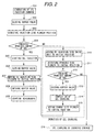
- FIG. 2 is a flowchart showing the gel charging operation in the electrophoretic instrument of FIG. 1.
- FIG. 3 is a cross-sectional view showing a check valve inserted between a charging syringe and a first passage.
- FIG. 4 is a front view of the check valve of FIG. 3 seeing from the block side.
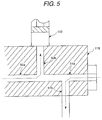
- FIG. 5 is an enlarged view of the inner flow passage of the block.
- FIG. 6 is a schematic view showing a linear encoder.
- FIG. 7 is a conceptual view of an optical detector of the linear encoder.
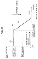
- FIG. 8 is a diagram showing change in moving speed of a drive unit depending on the positional relation of the drive unit and a syringe.
- FIG. 1a is a view showing the overall structure of an embodiment of an electrophoretic instrument in accordance with the present invention.
- Number of capillary formed of quartz tubes is at least one or more.
- a capillary array 118 is formed using a plurality of capillaries.
- One end of each of the capillaries containing the injected gel, not shown, is inserted into each of sample containers 122 in order to supply a sample to the capillary, and the capillaries in the other end side are bundled together before a detection part 117, and the ends of the bundle of the capillaries passing through the detection part 117 are inserted to a block 116 through a junction portion.
- FIG. 1a is a view showing the overall structure of an embodiment of an electrophoretic instrument in accordance with the present invention.
- Number of capillary formed of quartz tubes is at least one or more.
- a capillary array 118 is formed using a plurality of capillaries.
- FIG. 1b is a schematic view showing the capillary array, and the bundle portion of the array in the gel supplying side is inserted to the block, or the junction portion is joined with the flow passage of the flow passage.
- a cylindrical electrode 1 covering each of the capillaries is provided in the sample supply side of the capillaries.
- a common electrode 3, not shown, is integrally arranged in an array holder 3 so that the common electrode and the cylindrical electrodes 1 are connected to an electric power source 121 when the capillary array is attached to the array holder 3.
- the pairs of the capillary and the cylindrical electrode are inserted into sample containers 122 or a buffer container 123 to absorb samples or a buffer solution into the capillaries by the electrophoretic action.
- the capillary 118 is filled with a gel of a medium for separating a sample from the block 116 side before starting measurement.
- the outer surface of each of the capillaries is coated with a polyimide film in order to improve its mechanical strength, but the polyimide film at a position of the detector is peeled and removed off from the capillary so as to transmit excited light through the capillary and to extract generated fluorescence.
- a gel injection mechanism is composed of the block 116, an injection syringe 113, a charging syringe 114 and a check valve 115.
- the injection syringe 113 for injecting the electrophorsis medium gel such as a polymer gel into the capillaries 118 and the charging syringe 114 for charging the injection syringe 113 with the gel are attached to the block 116.
- the inside of the block 113 is composed of a first flow passage 52 communicating between the charging syringe 114 and the injection syringe 113 and a second flow passage 51 communicating between the injection syringe 113 and the capillaries 118.
- a branching passage to a buffer reservoir 126, which is to be in ground electric potential when performing electrophoresis, is provided at a position in the middle of the second flow passage.
- a check valve 115 is inserted between the charging syringe 114 and the first flow passage 52 to prevent the gel from flowing back to the charging syringe 114.
- the charging syringe 114 and the injection syringe 113 are pressed by driving motors 13, 14 controlled by a control unit 12 to move down drive units 17 and 18 attached to actuators 15, 16, respectively.
- Encoders 19 and 110 are attached to the drive units 17 and 18, respectively. Positional information of the drive units 17 and 18 obtained by reading values of the encoders is transmitted to the computer 11 through the control unit 12.
- the capillary array 118 is moved to a sample container 122 after being filled with the gel, and then moved to a buffer container 123 after sucking a sample by an electric action.
- a voltage is applied to the buffer container 123 through the electrode portion of the capillaries, an electric field is produced between the buffer container 123 and the buffer reservoir 126, and as the result, the samples in the capillaries are started to be electrophoresed.
- the introduced sample is separated because the electrophoretic mobility of a molecule differs depending on its molecular weight and so on, and therefore, the separated samples are detected at the detection part 117. Since the sample is labeled with a fluorescent substance in advance, the fluorescent substance is excited by a light source 119 at a detection part 117, and the fluorescence generated at that time is detected by a photo-detector 120 such as a CCD camera or the like.
- the base of terminal of the sample can be identified from the wavelength of the detected fluorescence by labeling the sample with specific fluorescent substances depending on the bases of terminal of the DNA such as adenine, guanine, thymine and cytosine.
- specific fluorescent substances depending on the bases of terminal of the DNA such as adenine, guanine, thymine and cytosine.
- FIG. 2 is a flowchart showing the gel charging operation.
- the control unit 12 receiving a command of gel injection from a computer 11 (201) initially closes a buffer valve 124 (202). After that, the drive unit 17 is moved down to automatically detect a position of a plunger 111 of the injection syringe 113 (203). An amount of gel remaining in the injection syringe 113 can be checked from a value of the linear encoder 19 in the injection side at that time (204). If the amount of the gel in the injection syringe 113 is insufficient, operation of charging the injection syringe 113 with the gel from the charging syringe 114 is performed in prior to gel injection to the capillary array 118.
- the gel charging operation is performed as following.
- the drive unit 17 in the injection side is moved to a position corresponding to a position of the plunger 111 of the injection syringe 113 at the time when the injection syringe 113 is filly filled with the gel (210).
- the drive unit 18 in the charging side is moved down to a position of the plunger 112 of the charging syringe 114 (211), and an remaining amount of the gel is checked from a value of the encoder 110 in the charging side (212). If the remaining amount is sufficient, the charging syringe 114 is stared to be pressed to start gel charging (213).
- the drive unit 17 in the injection side is started to press the injection syringe 113 to start gel injection to the capillaries 118 (205).
- the check valve 115 prevents the gel from flowing back to the charging syringe 114.
- the buffer valve 124 is closed, the gel pushed out from the injection syringe 113 flows into the capillaries 118 of only one flow passage to which the gel can flow out.
- the gel injection is completed when a certain mount of the gel is charged into the capillary, and the drive unit 17 in the injection side is stopped to press the injection syringe 113 (206), and moved upward in order to release the pressure, and stands by (207). Further, after the buffer valve 124 is opened (208), voltage is applied to the electrode portion of the capillaries to start electrophoresis (209).
- FIG. 3 shows a cross-sectional view when the check valve 16 is divided along the flow passage
- FIG. 4 shows a front view when the check valve 16 is seen from the block side.
- FIG. 5 shows an enlarged view of the flow passage in the block. Since the sample and ionized impurities flowing from the capillaries 118 into the flow passage 51a in the block flows toward the buffer reservoir 126 into which the electrode 127 in the ground electric potential is inserted, the gel flows toward the flow passage 51b from the flow passage 51a.
- the impurities can be prevented from entering and mixing with the gel filling in the capillaries 118 (the gel in the first flow passage and the both syringes) in the following measurement and from then on.
- a film 61 having slits 62 formed on a straight line is attached to the drive unit, and the slits pass through a photodetecting part 63 attached to the main body of the instrument when the drive unit is moved.
- the photodetecting unit 63 is composed of a light source part 71 having a light-emitting diode 72 as a light source and a lens for forming a parallel light beam; and a photo-sensor 74. Thereby, number of the slits passing between the light source part 71 and the photo-sensor 74 can be optically counted.
- the control unit 12 can recognize a movement per unit time of the drive unit by periodically checking the number counted by the detecting unit 63, and a position of the drive unit at the present time can be also known from the total movement.
- the detection of a plunger position described in the operation of gel injection will be described below in detail.
- the detection of a plunger position means an operation of the drive unit automatically moving down to the position of the plunger using a characteristic of a DC motor that the rotating speed varies depending on the magnitude of load.
- the operation principle will be described below, referring to FIG. 8.
- the rotating speed of the DC motor is drastically decreased (83), and the motor is finally locked to stop motion of the drive unit (84). Therefore, by setting a threshold at a speed slower than the normal speed of the drive unit described above, it is possible to judge whether or not the drive unit is in contact with the plunger. Actually, the value of the linear encoder is checked at a preset cycle, and when the movement of the drive unit becomes smaller than a preset threshold, it is judged that the drive unit is in contact with the plunger.
Landscapes
- Health & Medical Sciences (AREA)
- Life Sciences & Earth Sciences (AREA)
- Molecular Biology (AREA)
- Chemical & Material Sciences (AREA)
- Biochemistry (AREA)
- Electrochemistry (AREA)
- Physics & Mathematics (AREA)
- Analytical Chemistry (AREA)
- Chemical Kinetics & Catalysis (AREA)
- General Health & Medical Sciences (AREA)
- General Physics & Mathematics (AREA)
- Immunology (AREA)
- Pathology (AREA)
- Investigating, Analyzing Materials By Fluorescence Or Luminescence (AREA)
- Automatic Analysis And Handling Materials Therefor (AREA)
- Investigating Or Analysing Materials By Optical Means (AREA)
- Physical Or Chemical Processes And Apparatus (AREA)
Abstract
Description
Claims (12)
- An electrophoresis method comprising the steps of supplying a gel for electrophoresis to a bore of an injection syringe; driving a plunger of said injection syringe injecting the gel into a bore of a capillary through a flow passage communicating to said capillary; and supplying an analyzed sample to said capillary to separate said sample by electrophoresis, the method further comprising the steps of:detecting an amount of the gel remaining in said injection syringe;driving a plunger of a charging syringe to charge said flow passage in said block with the gel when the value of amount is smaller than a predetermined amount of the gel, the charging syringe being connected to said flow passage in said block through a check valve; thensupplying the gel to said capillary by the plunger of said injection syringe.
- An electrophoresis method according to claim 1, wherein said capillary is a capillary array having a plurality of capillaries, and a sample is electrophoretically moved from sample supply ends serving as a cathode of the capillaries toward a buffer reservoir serving as an anode.
- An electrophoresis method according to claim 1, the method further comprising the steps of obtaining amounts of the gel in said injection syringe and said charging syringe using encoders; injecting an amount of the gel necessary for once of the electrophoresis into said capillaries; then checking an amount of the gel remaining in said injection syringe; and supplying an amount of the gel necessary for the second and thereafter electrophoreses from said charging syringe into said injection syringe as required.
- An electrophoresis method according to claim 1, the method further comprising the steps of exciting the sample separated by the electrophoresis using an electromagnetic wave; and detecting fluorescence generated by the excitation.
- An electrophoretic instrument comprising:a capillary;a gel injection mechanism for injecting a gel of a sample separating medium into said capillary;a detecting unit for detecting a sample introduced into said capillary and electrophoretically separated;an injection syringe with a plunger for injecting said gel into said capillary;a charging syringe with a plunger for performing charging with said gel;a flow passage connecting between said syringes, said capillary and a buffer reservoira check valve for preventing said gel from flowing back to said charging syringe, said check valve being arranged between said charging syringe and said flow passage; andan encoder for obtaining an amount of the gel in said injection syringe.
- An electrophoretic instrument according to claim 5, which further comprises a light source for exciting the electrophoretically separated sample; and a detector for detecting fluorescence generated by the excitation.
- An electrophoretic instrument according to claim 5, wherein said flow passage is composed of a first flow passage communicating between said charging syringe and said injection syringe, and a second flow passage communicating between said injection syringe and said capillary.
- An electrophoretic instrument according to claim 5, wherein a branching passage to said buffer reservoir is provided at a middle position of said second flow passage, an electrode used at performing electrophoresis being inserted into said buffer reservoir.
- An electrophoretic instrument according to claim 5, which comprises motors for driving said injection syringe and said charging syringe.
- An electrophoretic instrument according to claim 9, which comprises a control unit for controlling a driving amount and sequence of said motor using a signal of said encoder.
- An electrophoretic instrument according to claim 10, wherein it is detected from a signal of said encoder that the plunger of said syringe is in contact with a drive unit.
- An electrophoretic instrument comprising:a capillary;a gel injection mechanism for injecting a gel of a sample separating medium into said capillary;a detecting unit for detecting a sample introduced into said capillary and electrophoretically separated;an injection syringe with a plunger for injecting said gel into said capillary;a charging syringe with a plunger for performing charging with said gel;a flow passage connecting between said syringes, said capillary and a buffer reservoira check valve for preventing said gel from flowing back to said charging syringe, said check valve being arranged between said charging syringe and said flow passage; andan encoder for detecting positional information of a drive unit.
Applications Claiming Priority (2)
| Application Number | Priority Date | Filing Date | Title |
|---|---|---|---|
| JP2000056042A JP3389547B2 (en) | 2000-02-28 | 2000-02-28 | Electrophoresis device |
| JP2000056042 | 2000-02-28 |
Publications (3)
| Publication Number | Publication Date |
|---|---|
| EP1128182A2 true EP1128182A2 (en) | 2001-08-29 |
| EP1128182A3 EP1128182A3 (en) | 2004-01-28 |
| EP1128182B1 EP1128182B1 (en) | 2007-10-03 |
Family
ID=18577068
Family Applications (1)
| Application Number | Title | Priority Date | Filing Date |
|---|---|---|---|
| EP01301697A Expired - Lifetime EP1128182B1 (en) | 2000-02-28 | 2001-02-26 | Electrophoretic method and electrophoretic instrument therefor |
Country Status (3)
| Country | Link |
|---|---|
| US (1) | US6660148B2 (en) |
| EP (1) | EP1128182B1 (en) |
| JP (1) | JP3389547B2 (en) |
Cited By (2)
| Publication number | Priority date | Publication date | Assignee | Title |
|---|---|---|---|---|
| WO2003062814A1 (en) | 2002-01-18 | 2003-07-31 | Hitachi High-Technologies Corporation | Capillary electrophoretic device |
| EP1467202A3 (en) * | 2003-04-11 | 2005-08-03 | Hitachi High-Technologies Corporation | Capillary electrophoresis apparatus |
Families Citing this family (14)
| Publication number | Priority date | Publication date | Assignee | Title |
|---|---|---|---|---|
| JP3492587B2 (en) | 2000-03-30 | 2004-02-03 | 株式会社日立製作所 | Electrophoresis device with plunger detection function |
| EP1979079A4 (en) | 2006-02-03 | 2012-11-28 | Integenx Inc | Microfluidic devices |
| JP4297922B2 (en) | 2006-06-27 | 2009-07-15 | 株式会社日立ハイテクノロジーズ | Capillary electrophoresis device |
| JP4843406B2 (en) * | 2006-08-07 | 2011-12-21 | 株式会社日立ハイテクノロジーズ | Capillary electrophoresis analyzer |
| KR101058541B1 (en) | 2010-02-25 | 2011-08-23 | 한국 한의학 연구원 | Electrophoresis device |
| EP2606154B1 (en) | 2010-08-20 | 2019-09-25 | Integenx Inc. | Integrated analysis system |
| US10865440B2 (en) | 2011-10-21 | 2020-12-15 | IntegenX, Inc. | Sample preparation, processing and analysis systems |
| US20150136604A1 (en) | 2011-10-21 | 2015-05-21 | Integenx Inc. | Sample preparation, processing and analysis systems |
| CN114471756B (en) | 2013-11-18 | 2024-04-16 | 尹特根埃克斯有限公司 | Cartridges and instruments for sample analysis |
| WO2015179098A1 (en) | 2014-05-21 | 2015-11-26 | Integenx Inc. | Fluidic cartridge with valve mechanism |
| CN107106983B (en) | 2014-10-22 | 2021-04-16 | 尹特根埃克斯有限公司 | Systems and methods for sample preparation, processing and analysis |
| CN107209149B (en) * | 2015-03-27 | 2020-06-30 | 株式会社日立高新技术 | Electrophoresis apparatus and electrophoresis method |
| CN111974316B (en) * | 2019-05-24 | 2024-11-26 | 南京英钛智能科技有限公司 | A gel preparation system |
| JP7289985B2 (en) * | 2020-03-06 | 2023-06-12 | 株式会社日立ハイテク | Measurement system and liquid transfer control method |
Family Cites Families (5)
| Publication number | Priority date | Publication date | Assignee | Title |
|---|---|---|---|---|
| EP0607495B1 (en) * | 1992-08-26 | 1998-01-14 | Hitachi, Ltd. | Capillary electrophoresis |
| US5409586A (en) * | 1992-08-26 | 1995-04-25 | Hitachi, Ltd. | Method for analyzing nucleic acid or protein and apparatus therefor |
| US5635050A (en) * | 1995-08-23 | 1997-06-03 | Beckman Instruments, Inc. | Electrophoretic system including means for replacing separation medium |
| US6027627A (en) * | 1997-06-30 | 2000-02-22 | Spectrumedix Corporation | Automated parallel capillary electrophoretic system |
| JP2000162183A (en) * | 1998-11-30 | 2000-06-16 | Inst Of Physical & Chemical Res | Capillary electrophoresis device |
-
2000
- 2000-02-28 JP JP2000056042A patent/JP3389547B2/en not_active Expired - Lifetime
-
2001
- 2001-02-26 US US09/793,242 patent/US6660148B2/en not_active Expired - Fee Related
- 2001-02-26 EP EP01301697A patent/EP1128182B1/en not_active Expired - Lifetime
Cited By (4)
| Publication number | Priority date | Publication date | Assignee | Title |
|---|---|---|---|---|
| WO2003062814A1 (en) | 2002-01-18 | 2003-07-31 | Hitachi High-Technologies Corporation | Capillary electrophoretic device |
| EP1378745B1 (en) * | 2002-01-18 | 2012-04-11 | Hitachi High-Technologies Corporation | Capillary electrophoretic device |
| EP1467202A3 (en) * | 2003-04-11 | 2005-08-03 | Hitachi High-Technologies Corporation | Capillary electrophoresis apparatus |
| US7419578B2 (en) | 2003-04-11 | 2008-09-02 | Hitachi High-Technologies Corporation | Capillary electrophoresis apparatus |
Also Published As
| Publication number | Publication date |
|---|---|
| US6660148B2 (en) | 2003-12-09 |
| EP1128182A3 (en) | 2004-01-28 |
| US20010017263A1 (en) | 2001-08-30 |
| JP3389547B2 (en) | 2003-03-24 |
| EP1128182B1 (en) | 2007-10-03 |
| JP2001242140A (en) | 2001-09-07 |
Similar Documents
| Publication | Publication Date | Title |
|---|---|---|
| US6660148B2 (en) | Electrophoretic method and electrophoretic instrument therefor | |
| US6905583B2 (en) | Closed-loop control of electrokinetic processes in microfluidic devices based on optical readings | |
| US7655125B2 (en) | Electrophoresis apparatus | |
| EP2609420B1 (en) | Disposible bio-analysis cartridge and instrument for conducting bio-analysis using same | |
| JPH10246721A (en) | Microchip electrophoresis device | |
| US8187442B2 (en) | Microchip processing method and apparatus | |
| US8257569B2 (en) | Capillary array unit and capillary electrophoresis apparatus | |
| KR101531064B1 (en) | Capillary electrophoresis using clear coated capillary tubes | |
| EP0854362A3 (en) | Multi-capillary electrophoresis apparatus | |
| US7208072B2 (en) | Multi-segment cartridge for bio-separation with multiplexed fluorescence detection | |
| EP1367388A1 (en) | Capillary electrophoresis apparatus and method | |
| US6383356B1 (en) | Capillary electrophoretic apparatus | |
| US20020144907A1 (en) | Apparatus and method of introducing a sample in a microchip electrophoresis | |
| JPH08101164A (en) | Capillary type electrophoresis device | |
| JP3492587B2 (en) | Electrophoresis device with plunger detection function | |
| US7931789B2 (en) | Device for charging separation buffer liquid to microchip, and microchip processing device equipped with the charging device, electrophoresis method in capillary channel and its microchip processing device | |
| JP4801007B2 (en) | Electrophoresis device and pump mechanism used therefor | |
| JP3562460B2 (en) | Electrophoresis device | |
| US12345994B2 (en) | Electrophoresis device | |
| JPH11108889A (en) | Capillary electrophoresis device | |
| JP2005062115A (en) | Chemiluminescence detection apparatus using capillary electrophoresis and analysis method using this chemiluminescence detection apparatus | |
| JP2000009690A (en) | Solution filling device for capillary electrophoresis | |
| JP2002350399A (en) | Gel injection device | |
| CN1234010C (en) | Electrophoresis separation analysis system | |
| EP2023135A1 (en) | Method for pretreatment of electrophoresis, substrate for analysis, and pretreatment apparatus for electrophoresis |
Legal Events
| Date | Code | Title | Description |
|---|---|---|---|
| PUAI | Public reference made under article 153(3) epc to a published international application that has entered the european phase |
Free format text: ORIGINAL CODE: 0009012 |
|
| 17P | Request for examination filed |
Effective date: 20010315 |
|
| AK | Designated contracting states |
Kind code of ref document: A2 Designated state(s): AT BE CH CY DE DK ES FI FR GB GR IE IT LI LU MC NL PT SE TR |
|
| AX | Request for extension of the european patent |
Free format text: AL;LT;LV;MK;RO;SI |
|
| PUAL | Search report despatched |
Free format text: ORIGINAL CODE: 0009013 |
|
| AK | Designated contracting states |
Kind code of ref document: A3 Designated state(s): AT BE CH CY DE DK ES FI FR GB GR IE IT LI LU MC NL PT SE TR |
|
| AX | Request for extension of the european patent |
Extension state: AL LT LV MK RO SI |
|
| AKX | Designation fees paid |
Designated state(s): FR GB |
|
| REG | Reference to a national code |
Ref country code: DE Ref legal event code: 8566 |
|
| GRAP | Despatch of communication of intention to grant a patent |
Free format text: ORIGINAL CODE: EPIDOSNIGR1 |
|
| GRAS | Grant fee paid |
Free format text: ORIGINAL CODE: EPIDOSNIGR3 |
|
| GRAA | (expected) grant |
Free format text: ORIGINAL CODE: 0009210 |
|
| AK | Designated contracting states |
Kind code of ref document: B1 Designated state(s): FR GB |
|
| REG | Reference to a national code |
Ref country code: GB Ref legal event code: FG4D |
|
| ET | Fr: translation filed | ||
| PLBE | No opposition filed within time limit |
Free format text: ORIGINAL CODE: 0009261 |
|
| STAA | Information on the status of an ep patent application or granted ep patent |
Free format text: STATUS: NO OPPOSITION FILED WITHIN TIME LIMIT |
|
| 26N | No opposition filed |
Effective date: 20080704 |
|
| REG | Reference to a national code |
Ref country code: FR Ref legal event code: PLFP Year of fee payment: 16 |
|
| REG | Reference to a national code |
Ref country code: FR Ref legal event code: PLFP Year of fee payment: 17 |
|
| REG | Reference to a national code |
Ref country code: FR Ref legal event code: PLFP Year of fee payment: 18 |
|
| PGFP | Annual fee paid to national office [announced via postgrant information from national office to epo] |
Ref country code: GB Payment date: 20200219 Year of fee payment: 20 |
|
| PGFP | Annual fee paid to national office [announced via postgrant information from national office to epo] |
Ref country code: FR Payment date: 20200113 Year of fee payment: 20 |
|
| REG | Reference to a national code |
Ref country code: GB Ref legal event code: PE20 Expiry date: 20210225 |
|
| PG25 | Lapsed in a contracting state [announced via postgrant information from national office to epo] |
Ref country code: GB Free format text: LAPSE BECAUSE OF EXPIRATION OF PROTECTION Effective date: 20210225 |