EP1128154B1 - Ballistic armor panel - Google Patents
Ballistic armor panel Download PDFInfo
- Publication number
- EP1128154B1 EP1128154B1 EP00124949A EP00124949A EP1128154B1 EP 1128154 B1 EP1128154 B1 EP 1128154B1 EP 00124949 A EP00124949 A EP 00124949A EP 00124949 A EP00124949 A EP 00124949A EP 1128154 B1 EP1128154 B1 EP 1128154B1
- Authority
- EP
- European Patent Office
- Prior art keywords
- foregoing
- ballistic armor
- armor panel
- board
- apertures
- Prior art date
- Legal status (The legal status is an assumption and is not a legal conclusion. Google has not performed a legal analysis and makes no representation as to the accuracy of the status listed.)
- Expired - Lifetime
Links
Images

Classifications
-
- F—MECHANICAL ENGINEERING; LIGHTING; HEATING; WEAPONS; BLASTING
- F41—WEAPONS
- F41H—ARMOUR; ARMOURED TURRETS; ARMOURED OR ARMED VEHICLES; MEANS OF ATTACK OR DEFENCE, e.g. CAMOUFLAGE, IN GENERAL
- F41H5/00—Armour; Armour plates
- F41H5/02—Plate construction
- F41H5/04—Plate construction composed of more than one layer
- F41H5/0414—Layered armour containing ceramic material
- F41H5/0421—Ceramic layers in combination with metal layers
-
- F—MECHANICAL ENGINEERING; LIGHTING; HEATING; WEAPONS; BLASTING
- F41—WEAPONS
- F41H—ARMOUR; ARMOURED TURRETS; ARMOURED OR ARMED VEHICLES; MEANS OF ATTACK OR DEFENCE, e.g. CAMOUFLAGE, IN GENERAL
- F41H5/00—Armour; Armour plates
- F41H5/02—Plate construction
- F41H5/023—Armour plate, or auxiliary armour plate mounted at a distance of the main armour plate, having cavities at its outer impact surface, or holes, for deflecting the projectile
Definitions
- This invention generally relates to ballistic armor panels of the type useful in protection of objects and equipment against small arms bullets and kinetic energy projectiles, i.e. fire arm rounds and projectiles artillery fragments and shrapnel.
- the invention is in particular concerned with a carrying board supporting a plurality of bodies.
- Ballistic armor panels are utilized for a variety of protective missions, in particular for reducing hit-risk of objects such as vehicles, equipment, structures, etc. from small arms projectiles, kinetic energy penetrators and from fragments of explosive charges, bombs, etc.
- armor panels are applied to the objects, which armor panels should be capable of stopping a bullet or a projectile or a fragment of an explosive charge within an extremely short distance, i.e. the effective thickness of the ballistic armor panel.
- a variety of armor panels are known, each typically comprising several layers of material holding a plurality of hard bodies typically made of ceramic material for effectively distributing the impact of a projectile, bullet, etc.
- the ceramic bodies are bonded to the carrying layers by suitable adhesive materials.
- carrier board It is known further a structure of carrier board as per FR2526535.
- the carrier board has annular apertures, which cannot be distributed in a honey comb fashion so as to keep the distance between adjacent apertures at a minimum.
- the present invention provides an improved ballistic armor panel for attaching to an object, according to the text of independent claim 1.
- the bodies are made of a ceramic material, such as, for example, alumina, silicone carbide, boron carbide, etc.
- the bodies may be made of a low density material although this is not a requirement.
- the bodies correspond in shape with the apertures of the board.
- Said bodies may be cylindrical or polygonal.
- the openings of the carrying board form together a honey-comb like shape.
- the apertures are formed with an annular rim extending into the aperture and being essentially flush with a surface of the carrying board remote from the object.
- the apertures taper from a face of the carrying board facing the object.
- the bodies may be also adhered within the apertures of the carrying board. They may also be adhered to a back layer of resilient material applied between the object and the carrying board. Such a layer may be made, for example, from laminates of ballistic fibers.
- the carrying board may be formed with suitable bores for directly attaching to a surface of the object. Any of the apertures of the board may serve as a bore.
- a ballistic panel 10 comprising a carrying board 12 made of a hard material such as, for example, steel, titanium, aluminum, composite materials, etc.
- the carrying board is formed with a plurality of apertures 16, which in the present example are cylindrical.
- the apertures 16 may be machined or may be pre-molded, e.g. when the carrying board is made of cast material.
- the thickness of the wall between adjoining apertures is between about 0.5 to 1 mm. However, this thickness may differ depending on different parameters such as type of materials and its mechanical properties, thickens of panel, etc.
- the carrying board 12 is formed with several bores 20, for connecting the panel to an object by bolts 22, etc. However, any one of the apertures 16 may also serve for attaching the board to the object (not shown).
- the object may be a structure, a vehicle, etc. and the board may be attached with possible use of different adapters.
- the bodies 24 are snugly received within the apertures 16 and their axial length does not exceed that of the apertures, whereby the bodies 24 do not project from a front face 30 of the carrying board 12.
- a bonding material may be applied between the walls of the bodies 24 and the apertures 16.
- the axial length of the bodies 24 is shorter than that of the apertures and the front faces 32 of the bodies are retracted so that they extend below the front face 30 of the carrying board, rendering the edges of the bodies less susceptible to external impact and to deterioration upon hitting by an external body thus reducing the damage of the bodies 24.
- FIG. 2 wherein an armor panel 40 is attached to an object 42 by bolts 44.
- the apertures 46 of the carrying member 48 are formed with an annular rim 50 at a front end thereof, essentially flush with the front face 54 of the panel. This arrangement is useful both for retaining the bodies 56 within the apertures 46 as well as for preventing deterioration of the edges of the front face 58 of the body 56.
- the carrying board 60 is formed with a plurality of apertures 62 tapering from a wide opening at a rear face facing the object (not shown) and a narrower opening at the front face 64 . This arrangement ensures that the bodies 66 do not disengage from the apertures of the carrying board.
- the carrying board 68 comprises tapering apertures 70 as in the embodiment of Fig. 3, with the addition that each aperture is formed with an annular rim 72 as in the embodiment of Fig. 2, whereby the bodies 74 supported in such apertures are shorter than those of Fig. 3 and are thus more protected.
- Fig. 5 represents still a further embodiment in which a ballistic panel 80 , which is similar to the embodiment of Fig. 1, (although any other of the previous embodiments may be selected).
- a thin layer of flexible material 82 such as a resilient material, Kevlar TM , Dyneema TM , fiberglass, laminate of ballistic fibers, etc. adhered to the back face of the carrying board 84 by a layer of adhesive substance 86, bonding the bodies 88 on the one hand, and providing some impact dampening on the other hand.
- a ballistic panel 98 formed with a plurality of polygonal apertures 100 (hexagonal in the specific embodiment, though any other polygonal shape will be suitable, e.g. triangular, square, hectagonal etc.) each fitted with a body 102 having a corresponding shape and retained as explained hereinbefore.
- Bolts 105 extend via edge apertures 103 and are fitted with washers 104 .
Landscapes
- Engineering & Computer Science (AREA)
- Chemical & Material Sciences (AREA)
- Ceramic Engineering (AREA)
- General Engineering & Computer Science (AREA)
- Aiming, Guidance, Guns With A Light Source, Armor, Camouflage, And Targets (AREA)
Description
- This invention generally relates to ballistic armor panels of the type useful in protection of objects and equipment against small arms bullets and kinetic energy projectiles, i.e. fire arm rounds and projectiles artillery fragments and shrapnel. The invention is in particular concerned with a carrying board supporting a plurality of bodies.
- Ballistic armor panels are utilized for a variety of protective missions, in particular for reducing hit-risk of objects such as vehicles, equipment, structures, etc. from small arms projectiles, kinetic energy penetrators and from fragments of explosive charges, bombs, etc. For that purpose, armor panels are applied to the objects, which armor panels should be capable of stopping a bullet or a projectile or a fragment of an explosive charge within an extremely short distance, i.e. the effective thickness of the ballistic armor panel.
- A variety of armor panels are known, each typically comprising several layers of material holding a plurality of hard bodies typically made of ceramic material for effectively distributing the impact of a projectile, bullet, etc. Typically the ceramic bodies are bonded to the carrying layers by suitable adhesive materials.
- One considerable disadvantage of heretofore known armor panels resides in that the carrying layers are not fitted for attaching directly to the object to be protected, whereby additional fixing means are required which are both heavy and somewhat cumbersome in assembly. A second disadvantage is the labor required for assembling protective panels of the aforementioned type. Evermore, the ceramic bodies are exposed and are thus vulnerable to mechanical damage and after a series of several hits they may brake and the ballistic panel may loose its effectiveness. In particular, the edges of the ceramic bodies are susceptible to damage and break easily, reducing the effectiveness of the armor panel
- There is known a security barrier structure described in EP 151011. Its content is taken as basis for the preamble of independent claim 1. This structure is not a ballistic armor panel but merely an anti-drill barrier for a safe to render it resistant to a drilling operation.
- It is known further a structure of carrier board as per FR2526535. In this structure the carrier board has annular apertures, which cannot be distributed in a honey comb fashion so as to keep the distance between adjacent apertures at a minimum.
- Still further there is known an abrasive resistant laminated article as described in US4307140. This artice is not suitable for protection of an object from projectiles, but is merely abrasion resistance lining, which is intended to be in sliding contact with abrasive agregates. The cover is designed as laminated plate in which abrasion resistant tiles are bonded to a cushioning support.
- It is thus an object of the present invention to provide a new and improved armor panel, which substantially reduces or overcomes the above drawbacks.
- The present invention provides an improved ballistic armor panel for attaching to an object, according to the text of independent claim 1. Typically, the bodies are made of a ceramic material, such as, for example, alumina, silicone carbide, boron carbide, etc. The bodies may be made of a low density material although this is not a requirement.
- Preferably, the bodies correspond in shape with the apertures of the board. Said bodies may be cylindrical or polygonal. By one specific design, where the bodies are polygonal, the openings of the carrying board form together a honey-comb like shape.
- Preferably, in order to retain the bodies within the apertures and to reduce their susceptibility to breakage, the apertures are formed with an annular rim extending into the aperture and being essentially flush with a surface of the carrying board remote from the object.
- According to a different embodiment, the apertures taper from a face of the carrying board facing the object.
- The bodies may be also adhered within the apertures of the carrying board. They may also be adhered to a back layer of resilient material applied between the object and the carrying board. Such a layer may be made, for example, from laminates of ballistic fibers.
- The carrying board may be formed with suitable bores for directly attaching to a surface of the object. Any of the apertures of the board may serve as a bore.
- In order to understand the invention and to see how it may be carried out in practice, a preferred embodiment will now be described, by way of non-limiting example only, with reference to the accompanying drawings, in which:
- Fig. 1 is perspective view, partially cut-out, of a ballistic armor panel according to a first embodiment of the present invention;
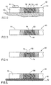
- Fig. 2 is a sectional view of a portion of a ballistic panel according to a modification of the invention, wherein the apertures are formed with an annular rim;
- Fig. 3 is a sectional view of a portion of a ballistic panel according to a still a modification of the invention, wherein the apertures taper;
- Fig. 4 is a sectional view illustrating a modification of the embodiment seen in Fig. 3 wherein the apertures taper and are formed with an annular rim;
- Fig. 5 is a sectional view illustrating a further application of the present invention, with a resilient back-layer provided at a back face of the carrier board;
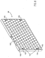
- Fig. 6 is a perspective view, partially cut-out, of still a different embodiment of the invention.
- Attention is first directed to Fig. 1 of the drawings in which a
ballistic panel 10 comprising a carryingboard 12 made of a hard material such as, for example, steel, titanium, aluminum, composite materials, etc. The carrying board is formed with a plurality ofapertures 16, which in the present example are cylindrical. Theapertures 16 may be machined or may be pre-molded, e.g. when the carrying board is made of cast material. - The thickness of the wall between adjoining apertures is between about 0.5 to 1 mm. However, this thickness may differ depending on different parameters such as type of materials and its mechanical properties, thickens of panel, etc.
- The
carrying board 12 is formed withseveral bores 20, for connecting the panel to an object bybolts 22, etc. However, any one of theapertures 16 may also serve for attaching the board to the object (not shown). The object may be a structure, a vehicle, etc. and the board may be attached with possible use of different adapters. - A plurality of
cylindrical bodies 24, made of an essentially hard material e.g. hard ceramics such as alumina, boron carbide, silicone carbide, glass, etc. are received within theapertures 16. Thebodies 24 are snugly received within theapertures 16 and their axial length does not exceed that of the apertures, whereby thebodies 24 do not project from afront face 30 of thecarrying board 12. - In order to prevent the
bodies 24 from spontaneously detaching from the carryingboard 12, a bonding material may be applied between the walls of thebodies 24 and theapertures 16. - According to one particular embodiment (not shown), the axial length of the
bodies 24 is shorter than that of the apertures and thefront faces 32 of the bodies are retracted so that they extend below thefront face 30 of the carrying board, rendering the edges of the bodies less susceptible to external impact and to deterioration upon hitting by an external body thus reducing the damage of thebodies 24. - Further attention is now directed to Fig. 2, wherein an
armor panel 40 is attached to anobject 42 bybolts 44. The apertures 46 of the carryingmember 48 are formed with an annular rim 50 at a front end thereof, essentially flush with thefront face 54 of the panel. This arrangement is useful both for retaining the bodies 56 within the apertures 46 as well as for preventing deterioration of the edges of the front face 58 of the body 56. - In Fig. 3 the
carrying board 60 is formed with a plurality ofapertures 62 tapering from a wide opening at a rear face facing the object (not shown) and a narrower opening at thefront face 64. This arrangement ensures that thebodies 66 do not disengage from the apertures of the carrying board. - In the embodiment of Fig. 4 the carrying
board 68 comprises taperingapertures 70 as in the embodiment of Fig. 3, with the addition that each aperture is formed with anannular rim 72 as in the embodiment of Fig. 2, whereby thebodies 74 supported in such apertures are shorter than those of Fig. 3 and are thus more protected. - Fig. 5 represents still a further embodiment in which a
ballistic panel 80, which is similar to the embodiment of Fig. 1, (although any other of the previous embodiments may be selected). In the present embodiment there is provided a thin layer of flexible material 82 (such as a resilient material, Kevlar™, Dyneema™, fiberglass, laminate of ballistic fibers, etc.) adhered to the back face of thecarrying board 84 by a layer ofadhesive substance 86, bonding thebodies 88 on the one hand, and providing some impact dampening on the other hand. - In Fig. 6 there is shown a
ballistic panel 98 formed with a plurality of polygonal apertures 100 (hexagonal in the specific embodiment, though any other polygonal shape will be suitable, e.g. triangular, square, hectagonal etc.) each fitted with abody 102 having a corresponding shape and retained as explained hereinbefore.Bolts 105 extend viaedge apertures 103 and are fitted withwashers 104. - As will be appreciated by a versed person, only some preferred embodiments have been shown and described in the specification and drawings.
Claims (15)
- A ballistic armor panel (10) for attaching to an object to protect it against small arms bullets and kinetic projectiles, the panel comprising a carrying board (12), said board being made of a hard material, said board is provided with a structure defined by a plurality of adjoining through-going apertures (16), distributed within the board, said panel (10) further comprising a plurality of bodies (24) made of a hard material, characterized in that each said body (24) is snugly received within a said aperture (16).
- A ballistic armor panel (10) according to Claim 1, wherein the bodies (24) correspond in shape with the apertures (16) of the carrying board (12).
- A ballistic armor panel (10) according to at least one of the foregoing claims, wherein the bodies (24) are cylindrical or polygonal.
- A ballistic armor panel (98) according to at least one of the foregoing claims, wherein the carrying board has a honey-comb like shape.
- A ballistic armor panel according to at least one of the foregoing daims, wherein the apertures (16) are formed with an annular rim (50) being flush with a face (54) of the carrying board remote from the object (42).
- A ballistic armor panel according to at least one of the foregoing claims, wherein the walls of the apertures (62) taper from a face (64) thereof facing the object.
- A ballistic armor panel according to at least one of the foregoing claims, wherein the bodies are fixed to the carrying board by an adhesive substance.
- A ballistic armor panel according to at least one of the foregoing claims, wherein the bodies are defined by an axial length and the board is defined by a thickness, wherein the axial length of said bodies does not exceed the thickness of the carrying board.
- A ballistic armor panel according to at least one of the foregoing claims, wherein the carrying board comprises bores (20) for attaching to the object (42).
- A ballistic armor panel according to at least one of the foregoing claims, wherein the carrying board is attached to the object by fasteners (22) extending through the apertures.
- A ballistic armor panel according to at least one of the foregoing claims, wherein a layer (82) of resilient material is provided intermediate the object and the carrying board.
- A ballistic armor panel according to at least one of the foregoing claims, wherein the wall thickness between adjoining apertures (16) is between about 0.5 mm to 1 mm.
- A ballistic armor panel as in at least one of the foregoing claims, in which the hard material of the board is any one of steel, titanium, or a ceramic material.
- A ballistic armor panel as in at least one of the foregoing claims, in which the hard material of the body (24) is any one of a ceramic material, or a silicone carbide.
- A ballistic armor panel (10) according to at least one of the foregoing claims, wherein said apertures (16; 62) are formed having a wide opening at a rear face of said board (16; 60) facing said object (42) and a narrower opening at a front face (64) of the board (12; 60).
Applications Claiming Priority (2)
| Application Number | Priority Date | Filing Date | Title |
|---|---|---|---|
| IL13464200A IL134642A0 (en) | 2000-02-21 | 2000-02-21 | Ballistic armor panel |
| IL13464200 | 2000-02-21 |
Publications (3)
| Publication Number | Publication Date |
|---|---|
| EP1128154A2 EP1128154A2 (en) | 2001-08-29 |
| EP1128154A3 EP1128154A3 (en) | 2001-11-14 |
| EP1128154B1 true EP1128154B1 (en) | 2006-06-21 |
Family
ID=11073858
Family Applications (1)
| Application Number | Title | Priority Date | Filing Date |
|---|---|---|---|
| EP00124949A Expired - Lifetime EP1128154B1 (en) | 2000-02-21 | 2000-11-15 | Ballistic armor panel |
Country Status (4)
| Country | Link |
|---|---|
| US (1) | US6892623B2 (en) |
| EP (1) | EP1128154B1 (en) |
| DE (1) | DE60028919T2 (en) |
| IL (1) | IL134642A0 (en) |
Cited By (1)
| Publication number | Priority date | Publication date | Assignee | Title |
|---|---|---|---|---|
| KR102068015B1 (en) * | 2018-10-04 | 2020-01-20 | 국방과학연구소 | Perforated steel-ball armor and manufacturing method thereof |
Families Citing this family (35)
| Publication number | Priority date | Publication date | Assignee | Title |
|---|---|---|---|---|
| US6826996B2 (en) * | 2002-03-11 | 2004-12-07 | General Dynamics Land Systems, Inc. | Structural composite armor and method of manufacturing it |
| IL149591A (en) * | 2002-05-12 | 2009-09-22 | Moshe Ravid | Ballistic armor |
| IL157584A (en) * | 2003-08-26 | 2008-07-08 | Cohen Michael | Composite armor plate |
| US7513186B2 (en) | 2004-03-11 | 2009-04-07 | Plasan-Kibbutz Sasa | Ballistic armor |
| AU2005327229A1 (en) | 2004-06-11 | 2006-08-17 | Stewart & Stevenson Tactical Vehicle Systems, L.P. | Armored cab for vehicles |
| US7322267B1 (en) * | 2004-06-15 | 2008-01-29 | Foi Group, Llc | Enhanced light weight armor system with reactive properties |
| US20060213360A1 (en) * | 2005-03-23 | 2006-09-28 | Mosche Ravid | Perforated armor plates |
| GB0506360D0 (en) | 2005-03-30 | 2005-05-04 | Secr Defence | A ceramic element for use in armour |
| US7661228B1 (en) | 2005-05-06 | 2010-02-16 | Kontek Industries, Inc. | Armored building modules and panels |
| WO2007055736A2 (en) * | 2005-05-26 | 2007-05-18 | Composix Co. | Ceramic multi-hit armor |
| US20070039837A1 (en) * | 2005-06-09 | 2007-02-22 | Erez Hanina | Energy dampening system and an element therefore |
| US7490539B2 (en) * | 2005-07-22 | 2009-02-17 | Mkp Structural Design Associates, Inc. | Lightweight composite armor |
| US7694621B1 (en) | 2005-07-22 | 2010-04-13 | Mkp Structural Design Associates, Inc. | Lightweight composite armor |
| US7389718B1 (en) | 2005-09-23 | 2008-06-24 | Carter Gerald D | Ballistic blanket |
| US7500422B2 (en) * | 2005-12-16 | 2009-03-10 | Robert Mazur | Modular functional star-disc system |
| US7866248B2 (en) * | 2006-01-23 | 2011-01-11 | Intellectual Property Holdings, Llc | Encapsulated ceramic composite armor |
| US7546796B2 (en) * | 2006-02-03 | 2009-06-16 | Lockheed Martin Corporation | Armor and method of making same |
| WO2008054867A2 (en) * | 2006-05-01 | 2008-05-08 | Warwick Mills, Inc. | Mosaic extremity protection system with transportable solid elements |
| US7703375B1 (en) * | 2006-08-15 | 2010-04-27 | Lawrence Technological University | Composite armor with a cellular structure |
| RU2329455C1 (en) * | 2007-01-24 | 2008-07-20 | Общество с ограниченной ответственностью "Научно-производственный Центр СПЛАВ" | Composite armour |
| US20080236378A1 (en) * | 2007-03-30 | 2008-10-02 | Intellectual Property Holdings, Llc | Affixable armor tiles |
| US8770085B2 (en) * | 2007-09-28 | 2014-07-08 | General Dynamics Land Systems, Inc. | Apparatus, methods and system for improved lightweight armor protection |
| US20100282062A1 (en) * | 2007-11-16 | 2010-11-11 | Intellectual Property Holdings, Llc | Armor protection against explosively-formed projectiles |
| US8096223B1 (en) * | 2008-01-03 | 2012-01-17 | Andrews Mark D | Multi-layer composite armor and method |
| IL192894A0 (en) * | 2008-07-17 | 2011-08-01 | Moshe Ravid | Armor panel |
| IL195090A0 (en) * | 2008-11-04 | 2009-09-22 | Gigi Simovich | A method and a device for pre-stressed armor |
| IL196191A (en) | 2008-12-25 | 2013-09-30 | Moshe Ravid | Armor plate |
| US8375841B2 (en) | 2009-06-17 | 2013-02-19 | Industrie Bitossi, S.p.A. | Armor tile |
| ITFI20090130A1 (en) * | 2009-06-17 | 2010-12-18 | Ind Bitossi Spa | COMPONENTS FOR CERAMIC CUPS. |
| DE102010000648B4 (en) * | 2010-03-05 | 2024-09-19 | Knds Deutschland Gmbh & Co. Kg | Composite armor element for protection against projectiles |
| US20110259184A1 (en) * | 2010-04-26 | 2011-10-27 | Adams Richard W | Multi-structure metal matrix composite armor with integrally cast holes |
| USD701821S1 (en) | 2010-12-16 | 2014-04-01 | Industrie Bitossi, S.p.A. | Armor tile |
| IL213397A (en) * | 2011-06-06 | 2015-05-31 | Ilan Gavish | Stand-off armor module and method for formation thereof |
| US9658033B1 (en) * | 2012-05-18 | 2017-05-23 | Armorworks Enterprises LLC | Lattice reinforced armor array |
| CA2974304C (en) * | 2015-01-19 | 2021-01-26 | Flsmidth A/S | Interlocking wear-resistant panel system |
Family Cites Families (21)
| Publication number | Priority date | Publication date | Assignee | Title |
|---|---|---|---|---|
| GB127321A (en) * | 1917-04-18 | 1919-06-05 | Thomas George Herbert Burton | Improvements in Bullet Proof Shields, Armour, and like Projectile Resisting Devices. |
| US5456156A (en) * | 1965-09-14 | 1995-10-10 | The United States Of America As Represented By The Secretary Of The Army | Ceramic armor |
| US3634177A (en) * | 1966-11-01 | 1972-01-11 | Gen Electric | Lightweight transparent penetration-resistant structure |
| DE1719543B2 (en) * | 1968-02-17 | 1976-06-16 | PROCESS FOR ANTI-ELECTROSTATIC EQUIPMENT OF FABRICS, FIBERS AND TEXTILES MADE OF POLYESTER OR POLYAMIDE | |
| US3874855A (en) * | 1969-07-22 | 1975-04-01 | Cegedur Gp | Composite shock resisting bodies |
| FR2419498A1 (en) * | 1978-03-08 | 1979-10-05 | Merlin Gerin | CAST COMPOSITE SHIELD |
| US4198454A (en) * | 1978-10-27 | 1980-04-15 | American Air Filter Company, Inc. | Lightweight composite panel |
| US4307140A (en) * | 1980-07-31 | 1981-12-22 | Davis Thomas E | Abrasive resistant laminated article and method of manufacture |
| FR2526535A1 (en) * | 1982-05-04 | 1983-11-10 | Pequignot Michel | SHIELDING PLATE, ESPECIALLY FOR LIGHT SHIELDING |
| US4529640A (en) * | 1983-04-08 | 1985-07-16 | Goodyear Aerospace Corporation | Spaced armor |
| GB2153406B (en) * | 1984-01-26 | 1987-04-15 | Chubb & Sons Lock & Safe Co | Anti-drill barrier structure for safe or strongroom doors or walls |
| US4841838A (en) * | 1987-10-13 | 1989-06-27 | Scully Andrew J | Armor retension mechanism having anti-theft means |
| US5014593A (en) * | 1988-03-01 | 1991-05-14 | General Dynamics Land Systems, Inc. | Perforated plate armor |
| WO1991007632A1 (en) * | 1989-11-13 | 1991-05-30 | Allied-Signal Inc. | Ballistic resistant composite armor |
| FR2655413B1 (en) * | 1989-12-06 | 1994-06-03 | Europ Propulsion | BALLISTIC PROTECTION SHIELD. |
| US5349893A (en) * | 1992-02-20 | 1994-09-27 | Dunn Eric S | Impact absorbing armor |
| USH1434H (en) * | 1993-08-30 | 1995-05-02 | The United States Of America As Represented By The Secretary Of The Army | Method and apparatus for conformal embedded ceramic armor |
| IL119386A (en) * | 1996-10-09 | 2000-09-28 | Cohen Michael | Composite armor |
| US6289781B1 (en) * | 1996-08-26 | 2001-09-18 | Michael Cohen | Composite armor plates and panel |
| US6203908B1 (en) * | 1996-08-26 | 2001-03-20 | Michael Cohen | Composite armor |
| AU6173698A (en) * | 1997-02-19 | 1998-09-09 | Franklin C. Moore | Composite armor for a vehicle and method for manufacturing such an armour |
-
2000
- 2000-02-21 IL IL13464200A patent/IL134642A0/en not_active IP Right Cessation
- 2000-11-15 EP EP00124949A patent/EP1128154B1/en not_active Expired - Lifetime
- 2000-11-15 DE DE60028919T patent/DE60028919T2/en not_active Expired - Lifetime
-
2001
- 2001-02-16 US US09/785,072 patent/US6892623B2/en not_active Expired - Fee Related
Cited By (1)
| Publication number | Priority date | Publication date | Assignee | Title |
|---|---|---|---|---|
| KR102068015B1 (en) * | 2018-10-04 | 2020-01-20 | 국방과학연구소 | Perforated steel-ball armor and manufacturing method thereof |
Also Published As
| Publication number | Publication date |
|---|---|
| DE60028919T2 (en) | 2007-07-12 |
| US6892623B2 (en) | 2005-05-17 |
| IL134642A0 (en) | 2001-05-20 |
| DE60028919D1 (en) | 2006-08-03 |
| US20010032541A1 (en) | 2001-10-25 |
| EP1128154A3 (en) | 2001-11-14 |
| EP1128154A2 (en) | 2001-08-29 |
Similar Documents
| Publication | Publication Date | Title |
|---|---|---|
| US6892623B2 (en) | Ballistic armor panel | |
| US5221807A (en) | Ballistic protection armor | |
| US7513186B2 (en) | Ballistic armor | |
| AU2012267563B2 (en) | Enhanced ballistic protective system | |
| EP1409948B1 (en) | Ceramic armour systems with a front spall layer and a shock absorbing layer | |
| US6408733B1 (en) | Ceramic armor apparatus for multiple bullet protection | |
| US7562612B2 (en) | Ceramic components, ceramic component systems, and ceramic armour systems | |
| EP1352207B1 (en) | Laminated armor | |
| EP1322904B1 (en) | Composite armor panel | |
| US20060213360A1 (en) | Perforated armor plates | |
| US7077048B1 (en) | Multi-layered trap ballistic armor | |
| IL160843A (en) | Ballistic armor with particularly a layer of hard bodies | |
| EP1522817B1 (en) | A composite armor plate and ceramic bodies for use therein | |
| US4869152A (en) | Combined active and passive armor system | |
| US6718861B1 (en) | Momentum trap ballistic armor system | |
| EP1080337B1 (en) | Composite armor plate | |
| AU1175200A (en) | Ballistic armor panel | |
| RU160384U1 (en) | MULTILAYER ARMOR | |
| EP2202479A2 (en) | Armor Plate | |
| US20110113951A1 (en) | Protection of personnel and articles from impact of ballistic devices | |
| RU160711U1 (en) | MULTILAYER ARMOR | |
| EP1605224A2 (en) | A passive armor assembly including an armor member made of a brittle material | |
| RU2247301C2 (en) | Armor protection |
Legal Events
| Date | Code | Title | Description |
|---|---|---|---|
| PUAI | Public reference made under article 153(3) epc to a published international application that has entered the european phase |
Free format text: ORIGINAL CODE: 0009012 |
|
| AK | Designated contracting states |
Kind code of ref document: A2 Designated state(s): DE FR GB Kind code of ref document: A2 Designated state(s): AT BE CH CY DE DK ES FI FR GB GR IE IT LI LU MC NL PT SE TR |
|
| AX | Request for extension of the european patent |
Free format text: AL;LT;LV;MK;RO;SI |
|
| PUAL | Search report despatched |
Free format text: ORIGINAL CODE: 0009013 |
|
| AK | Designated contracting states |
Kind code of ref document: A3 Designated state(s): AT BE CH CY DE DK ES FI FR GB GR IE IT LI LU MC NL PT SE TR |
|
| AX | Request for extension of the european patent |
Free format text: AL;LT;LV;MK;RO;SI |
|
| RAP1 | Party data changed (applicant data changed or rights of an application transferred) |
Owner name: RAFAEL ARMAMENT DEVELOPMENT AUTHORITY LTD. |
|
| 17P | Request for examination filed |
Effective date: 20020412 |
|
| AKX | Designation fees paid |
Free format text: DE FR GB |
|
| 17Q | First examination report despatched |
Effective date: 20031211 |
|
| GRAP | Despatch of communication of intention to grant a patent |
Free format text: ORIGINAL CODE: EPIDOSNIGR1 |
|
| GRAS | Grant fee paid |
Free format text: ORIGINAL CODE: EPIDOSNIGR3 |
|
| GRAA | (expected) grant |
Free format text: ORIGINAL CODE: 0009210 |
|
| AK | Designated contracting states |
Kind code of ref document: B1 Designated state(s): DE FR GB |
|
| REG | Reference to a national code |
Ref country code: GB Ref legal event code: FG4D |
|
| REF | Corresponds to: |
Ref document number: 60028919 Country of ref document: DE Date of ref document: 20060803 Kind code of ref document: P |
|
| ET | Fr: translation filed | ||
| PLBE | No opposition filed within time limit |
Free format text: ORIGINAL CODE: 0009261 |
|
| STAA | Information on the status of an ep patent application or granted ep patent |
Free format text: STATUS: NO OPPOSITION FILED WITHIN TIME LIMIT |
|
| 26N | No opposition filed |
Effective date: 20070322 |
|
| PGFP | Annual fee paid to national office [announced via postgrant information from national office to epo] |
Ref country code: DE Payment date: 20091119 Year of fee payment: 10 |
|
| PGFP | Annual fee paid to national office [announced via postgrant information from national office to epo] |
Ref country code: FR Payment date: 20091204 Year of fee payment: 10 Ref country code: GB Payment date: 20091111 Year of fee payment: 10 |
|
| GBPC | Gb: european patent ceased through non-payment of renewal fee |
Effective date: 20101115 |
|
| REG | Reference to a national code |
Ref country code: DE Ref legal event code: R119 Ref document number: 60028919 Country of ref document: DE Effective date: 20110601 Ref country code: DE Ref legal event code: R119 Ref document number: 60028919 Country of ref document: DE Effective date: 20110531 |
|
| REG | Reference to a national code |
Ref country code: FR Ref legal event code: ST Effective date: 20110801 |
|
| PG25 | Lapsed in a contracting state [announced via postgrant information from national office to epo] |
Ref country code: DE Free format text: LAPSE BECAUSE OF NON-PAYMENT OF DUE FEES Effective date: 20110531 |
|
| PG25 | Lapsed in a contracting state [announced via postgrant information from national office to epo] |
Ref country code: FR Free format text: LAPSE BECAUSE OF NON-PAYMENT OF DUE FEES Effective date: 20101130 |
|
| PG25 | Lapsed in a contracting state [announced via postgrant information from national office to epo] |
Ref country code: GB Free format text: LAPSE BECAUSE OF NON-PAYMENT OF DUE FEES Effective date: 20101115 |