EP1128078B1 - Sealing device for a rolling contact bearing - Google Patents
Sealing device for a rolling contact bearing Download PDFInfo
- Publication number
- EP1128078B1 EP1128078B1 EP00126814A EP00126814A EP1128078B1 EP 1128078 B1 EP1128078 B1 EP 1128078B1 EP 00126814 A EP00126814 A EP 00126814A EP 00126814 A EP00126814 A EP 00126814A EP 1128078 B1 EP1128078 B1 EP 1128078B1
- Authority
- EP
- European Patent Office
- Prior art keywords
- sealing
- sealing device
- contact
- lip
- fact
- Prior art date
- Legal status (The legal status is an assumption and is not a legal conclusion. Google has not performed a legal analysis and makes no representation as to the accuracy of the status listed.)
- Expired - Lifetime
Links
Images
Classifications
-
- F—MECHANICAL ENGINEERING; LIGHTING; HEATING; WEAPONS; BLASTING
- F16—ENGINEERING ELEMENTS AND UNITS; GENERAL MEASURES FOR PRODUCING AND MAINTAINING EFFECTIVE FUNCTIONING OF MACHINES OR INSTALLATIONS; THERMAL INSULATION IN GENERAL
- F16C—SHAFTS; FLEXIBLE SHAFTS; ELEMENTS OR CRANKSHAFT MECHANISMS; ROTARY BODIES OTHER THAN GEARING ELEMENTS; BEARINGS
- F16C33/00—Parts of bearings; Special methods for making bearings or parts thereof
- F16C33/72—Sealings
- F16C33/76—Sealings of ball or roller bearings
- F16C33/78—Sealings of ball or roller bearings with a diaphragm, disc, or ring, with or without resilient members
- F16C33/7886—Sealings of ball or roller bearings with a diaphragm, disc, or ring, with or without resilient members mounted outside the gap between the inner and outer races, e.g. sealing rings mounted to an end face or outer surface of a race
-
- F—MECHANICAL ENGINEERING; LIGHTING; HEATING; WEAPONS; BLASTING
- F16—ENGINEERING ELEMENTS AND UNITS; GENERAL MEASURES FOR PRODUCING AND MAINTAINING EFFECTIVE FUNCTIONING OF MACHINES OR INSTALLATIONS; THERMAL INSULATION IN GENERAL
- F16C—SHAFTS; FLEXIBLE SHAFTS; ELEMENTS OR CRANKSHAFT MECHANISMS; ROTARY BODIES OTHER THAN GEARING ELEMENTS; BEARINGS
- F16C33/00—Parts of bearings; Special methods for making bearings or parts thereof
- F16C33/72—Sealings
- F16C33/76—Sealings of ball or roller bearings
- F16C33/78—Sealings of ball or roller bearings with a diaphragm, disc, or ring, with or without resilient members
- F16C33/7816—Details of the sealing or parts thereof, e.g. geometry, material
- F16C33/782—Details of the sealing or parts thereof, e.g. geometry, material of the sealing region
- F16C33/7823—Details of the sealing or parts thereof, e.g. geometry, material of the sealing region of sealing lips
-
- F—MECHANICAL ENGINEERING; LIGHTING; HEATING; WEAPONS; BLASTING
- F16—ENGINEERING ELEMENTS AND UNITS; GENERAL MEASURES FOR PRODUCING AND MAINTAINING EFFECTIVE FUNCTIONING OF MACHINES OR INSTALLATIONS; THERMAL INSULATION IN GENERAL
- F16C—SHAFTS; FLEXIBLE SHAFTS; ELEMENTS OR CRANKSHAFT MECHANISMS; ROTARY BODIES OTHER THAN GEARING ELEMENTS; BEARINGS
- F16C19/00—Bearings with rolling contact, for exclusively rotary movement
- F16C19/02—Bearings with rolling contact, for exclusively rotary movement with bearing balls essentially of the same size in one or more circular rows
- F16C19/14—Bearings with rolling contact, for exclusively rotary movement with bearing balls essentially of the same size in one or more circular rows for both radial and axial load
- F16C19/18—Bearings with rolling contact, for exclusively rotary movement with bearing balls essentially of the same size in one or more circular rows for both radial and axial load with two or more rows of balls
- F16C19/181—Bearings with rolling contact, for exclusively rotary movement with bearing balls essentially of the same size in one or more circular rows for both radial and axial load with two or more rows of balls with angular contact
- F16C19/183—Bearings with rolling contact, for exclusively rotary movement with bearing balls essentially of the same size in one or more circular rows for both radial and axial load with two or more rows of balls with angular contact with two rows at opposite angles
- F16C19/184—Bearings with rolling contact, for exclusively rotary movement with bearing balls essentially of the same size in one or more circular rows for both radial and axial load with two or more rows of balls with angular contact with two rows at opposite angles in O-arrangement
- F16C19/186—Bearings with rolling contact, for exclusively rotary movement with bearing balls essentially of the same size in one or more circular rows for both radial and axial load with two or more rows of balls with angular contact with two rows at opposite angles in O-arrangement with three raceways provided integrally on parts other than race rings, e.g. third generation hubs
-
- F—MECHANICAL ENGINEERING; LIGHTING; HEATING; WEAPONS; BLASTING
- F16—ENGINEERING ELEMENTS AND UNITS; GENERAL MEASURES FOR PRODUCING AND MAINTAINING EFFECTIVE FUNCTIONING OF MACHINES OR INSTALLATIONS; THERMAL INSULATION IN GENERAL
- F16C—SHAFTS; FLEXIBLE SHAFTS; ELEMENTS OR CRANKSHAFT MECHANISMS; ROTARY BODIES OTHER THAN GEARING ELEMENTS; BEARINGS
- F16C2326/00—Articles relating to transporting
- F16C2326/01—Parts of vehicles in general
- F16C2326/02—Wheel hubs or castors
Definitions
- the present invention relates to a sealing device for a rolling contact bearing according to the preamble of claim 1.
- Such a sealing device is known from FR 2 688 567 A.
- the present invention is advantageous for application in the field of rolling contact bearings for rolling contact bearing hub groups to be used in vehicle wheels, the description which follows hereinafter will make specific reference to this area.
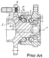
- Roll contact bearing hub groups such as, for example, the one illustrated in the diagram entitled "Prior Art", present a longitudinal A axis and, usually, comprise a central revolving hub 2 defining a radially internal rolling track 3 for a series 4 of axially external spheres; an annular element 5 which is trigged onto the hub 2 and which defines another rolling track 6 which is radially internal for a series 7 of axially internal spheres; and a radially external fixed ring 8, which is coaxial to the hub 2, and which defines the external rolling track 9 for the two series 4 and 7 of spheres.
- the hub 2 also comprises, on the opposite side to that which supports the annular element 5, a flange 10 which is jointed to the track 3 via a conical surface 11 with a generating curve, while the ring 8 comprises, on the part turned towards the outside of the rolling contact bearing hub group, a cylindrical end portion 12 which directly faces the surface 11, with which it defines an annular opening 13.
- the rolling contact bearing hub group which has just been described also comprises a sealing device 14, which is mounted onto a sealing portion 12 to close the opening 13 in order to render the internal parts of the group itself hermetic, these parts are actually those which house the two series 4 and 7 of spheres and they comprise: a metal insert 15 which is directly coupled to the portion 12, and a vulcanised rubber body 16 on a free portion 17 of the insert 15 itself.
- the body 16 comprises five lips L2 - L6, of which the lips L2 and L3 axially extend from the portion 17 towards the portion 12 and, respectively, towards the surface 11, the lips L4 and L5 axially extend towards the outside of the portion 17 and are parallel to each other, and they are arranged in sliding contact with the surface 11, while the lip L6 is radially arranged outside the lips L4 and L5, and it axially extends towards the outside of the insert 15, and it is substantially spaced from the surface 11 in such a way as to counteract the action of the solid impurities which co-operate with the other lips in the sealing action of the device 14.
- the sealing device which has just been described, although it has been demonstrated to be quite suitable for performing its function and also quite efficient in that performance, does present some drawback which are essentially determined by the number of lips. In fact, from a purely technical point of view, the presence of these lips can lead to some difficulties during assembly, while, from an economic point of view, it is obvious that the manufacturing costs regarding such a sealing device can be relatively high.
- the aim of the present invention is to produce a sealing device for a rolling contact bearing, with a high level of sealing capacity, and which is easy and cost-effective to manufacture.
- a sealing device for a rolling contact bearing according to claim 1 will be produced.
- the number 20 indicates, in its entirety, a sealing device which is suitable for being mounted on a sealing portion 12 to close the opening 13 in order to hermetically seal the pace between the hub 2 and the ring 8.
- the sealing device 20 defines a considerable improvement with regard to the sealing device 14 which has been previously been described as it solves the problems of the drawbacks already discussed in the introduction, and it is different from the device 14 itself firstly because the lips L4 and L5 are replaced by a single lip L1, which axially extends towards the outside starting from the portion 17, and which is arranged in sliding contact with the surface 11, and secondly because the lip L5 is arranged in a position which is much nearer to the surface 11.
- the metal insert 15 is applied onto the portion 12, and it comprises a cylindrical portion 15a which is arranged around the portion 12 itself as well as an annular portion 15b, which is frontally arranged to the portion 12, and which defines with the cylindrical portion 15a and in a transverse section of the insert 15 a substantially L-shaped form for the insert 15 itself.
- the free portion 17 of the insert 15 extends radially and axially towards the outside starting from the portion 15b and projects with regard to the portion 12, and it comprises a conical portion 17a which is directly connected to the portion 15b, and an annular portion 17b which extends starting from the conical portion 17a in order to define both a support for the body 16 and a starting point for the lip L6.
- the device 10 presents a single lip L1, which is a double contact lip and which has two points of contacts P1 and P2 with the contact surface 11, and which comprises two substantially conical portions 21 and 22 which are arranged in series in relation to each other, and of which the portion 21 presents a thickness S1 which is greater than a thickness S2 of the portion 22, and which defines a chamber 23 between the two points P1 and P2 which are suitable for functioning as a depression valve for hermetically sealing the rolling contact bearing during the cooling of the rolling contact bearing hub group.
- points P1 and P2 are defined by respective contact circumferences which extend around the A axis on the surface 11.
- the portions 21 and 22 are both radially limited towards the outside by a single and continuous surface 24, while, due to their different thickness, they are radially limited towards the inside by two respective surfaces 21s and 22s, of which the surface 21s ends in correspondence with an annular edge 25 defining the point of contact- P1, while the surface 22s ends in correspondence with a respective annular edge 26 defining the point of contact P2. Both the edge 25 and the edge 26 present a substantially rectangular shape in transverse section.
- the conical surface 11 with a curved generating line is arranged with its own smaller base turned towards the inside of the rolling contact bearing hub group and with a larger base turned towards the outside of the group itself, so that the edge 25 presents a diameter which is smaller than the diameter of the edge 26.
- the lip L6 of the device 20 axially extends towards the surface 11 starting directly from the annular portion 15b of the insert 15, and it presents a substantially isosceles triangle shape in transverse section, the peak of which is, however, thickened by the presence of a projection 27 on its external side which is suitable for improving the performance of the lip L6 itself.
Description
- The present invention relates to a sealing device for a rolling contact bearing according to the preamble of claim 1.
- Such a sealing device is known from
FR 2 688 567 A. - The present invention is advantageous for application in the field of rolling contact bearings for rolling contact bearing hub groups to be used in vehicle wheels, the description which follows hereinafter will make specific reference to this area.
- Well-known types of rolling contact bearing hub groups, such as, for example, the one illustrated in the diagram entitled "Prior Art", present a longitudinal A axis and, usually, comprise a central revolving
hub 2 defining a radially internalrolling track 3 for aseries 4 of axially external spheres; anannular element 5 which is trigged onto thehub 2 and which defines another rolling track 6 which is radially internal for aseries 7 of axially internal spheres; and a radially external fixedring 8, which is coaxial to thehub 2, and which defines the external rolling track 9 for the twoseries - The
hub 2 also comprises, on the opposite side to that which supports theannular element 5, a flange 10 which is jointed to thetrack 3 via a conical surface 11 with a generating curve, while thering 8 comprises, on the part turned towards the outside of the rolling contact bearing hub group, acylindrical end portion 12 which directly faces the surface 11, with which it defines an annular opening 13. - The rolling contact bearing hub group which has just been described also comprises a sealing device 14, which is mounted onto a
sealing portion 12 to close the opening 13 in order to render the internal parts of the group itself hermetic, these parts are actually those which house the twoseries metal insert 15 which is directly coupled to theportion 12, and avulcanised rubber body 16 on a free portion 17 of theinsert 15 itself. - The
body 16 comprises five lips L2 - L6, of which the lips L2 and L3 axially extend from the portion 17 towards theportion 12 and, respectively, towards the surface 11, the lips L4 and L5 axially extend towards the outside of the portion 17 and are parallel to each other, and they are arranged in sliding contact with the surface 11, while the lip L6 is radially arranged outside the lips L4 and L5, and it axially extends towards the outside of theinsert 15, and it is substantially spaced from the surface 11 in such a way as to counteract the action of the solid impurities which co-operate with the other lips in the sealing action of the device 14. - The sealing device which has just been described, although it has been demonstrated to be quite suitable for performing its function and also quite efficient in that performance, does present some drawback which are essentially determined by the number of lips. In fact, from a purely technical point of view, the presence of these lips can lead to some difficulties during assembly, while, from an economic point of view, it is obvious that the manufacturing costs regarding such a sealing device can be relatively high.
- The aim of the present invention is to produce a sealing device for a rolling contact bearing, with a high level of sealing capacity, and which is easy and cost-effective to manufacture.
- According to the present invention, a sealing device for a rolling contact bearing according to claim 1 will be produced.
- The present invention will now be described with reference to the attached drawing, which illustrates a non-limiting embodiment of the present invention itself and in which:
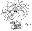
- FIGURE 1 shows an axial section, with some parts removed for reasons of clarity, of a first preferred embodiment of the sealing device according to the present invention; and
- Making reference to FIGURE 1, and using the same reference numbers to indicate the same or similar parts which have already been described in the initial part of the description, the
number 20 indicates, in its entirety, a sealing device which is suitable for being mounted on asealing portion 12 to close the opening 13 in order to hermetically seal the pace between thehub 2 and thering 8. - The
sealing device 20 defines a considerable improvement with regard to the sealing device 14 which has been previously been described as it solves the problems of the drawbacks already discussed in the introduction, and it is different from the device 14 itself firstly because the lips L4 and L5 are replaced by a single lip L1, which axially extends towards the outside starting from the portion 17, and which is arranged in sliding contact with the surface 11, and secondly because the lip L5 is arranged in a position which is much nearer to the surface 11. - In particular, in the embodiment shown in FIGURE 1, the
metal insert 15 is applied onto theportion 12, and it comprises a cylindrical portion 15a which is arranged around theportion 12 itself as well as an annular portion 15b, which is frontally arranged to theportion 12, and which defines with the cylindrical portion 15a and in a transverse section of the insert 15 a substantially L-shaped form for theinsert 15 itself. The free portion 17 of theinsert 15 extends radially and axially towards the outside starting from the portion 15b and projects with regard to theportion 12, and it comprises a conical portion 17a which is directly connected to the portion 15b, and anannular portion 17b which extends starting from the conical portion 17a in order to define both a support for thebody 16 and a starting point for the lip L6. - As has previously been described, the device 10 presents a single lip L1, which is a double contact lip and which has two points of contacts P1 and P2 with the contact surface 11, and which comprises two substantially
conical portions 21 and 22 which are arranged in series in relation to each other, and of which the portion 21 presents a thickness S1 which is greater than a thickness S2 of theportion 22, and which defines achamber 23 between the two points P1 and P2 which are suitable for functioning as a depression valve for hermetically sealing the rolling contact bearing during the cooling of the rolling contact bearing hub group. - Hereinafter, the term "point of contact" will indicate, for reasons of simplifying the description, two single points of contact between the lip L1 and the surface 11, as illustrated if FIGURE 1, but in reality the points P1 and P2 are defined by respective contact circumferences which extend around the A axis on the surface 11.
- The
portions 21 and 22 are both radially limited towards the outside by a single andcontinuous surface 24, while, due to their different thickness, they are radially limited towards the inside by two respective surfaces 21s and 22s, of which the surface 21s ends in correspondence with anannular edge 25 defining the point of contact- P1, while the surface 22s ends in correspondence with a respective annular edge 26 defining the point of contact P2. Both theedge 25 and the edge 26 present a substantially rectangular shape in transverse section. - The conical surface 11 with a curved generating line is arranged with its own smaller base turned towards the inside of the rolling contact bearing hub group and with a larger base turned towards the outside of the group itself, so that the
edge 25 presents a diameter which is smaller than the diameter of the edge 26. - The lip L6 of the
device 20 axially extends towards the surface 11 starting directly from the annular portion 15b of theinsert 15, and it presents a substantially isosceles triangle shape in transverse section, the peak of which is, however, thickened by the presence of aprojection 27 on its external side which is suitable for improving the performance of the lip L6 itself. - An additional' advantage which is derived from the integral construction of the lips L5 and L4 into a single lip L1, as previously described in the introduction, is the fact that both the
sealing device 20 and the sealing device 30 present a reduced radial dimension in relation to sealing devices of a well-known type and that they are thus more easily adaptable to different kinds of rolling contact bearings.
Claims (5)
- Sealing device (20) for a rolling contact bearing hub group which comprises a hub (2) defining a contact surface (11), the sealing device (20) presenting a substantially rigid insert (15) which may be installed on a fixed portion (8) of the rolling contact bearing and at least one first sealing contact lip (L1) which extends from the insert (15) itself towards the contact surface (11) and which comprises a first and a second sealing portion (21) (22) which are arranged in series in relation to each other, and are in sliding contact with the said contact surface (11) in correspondence with respective contact edges (25, 26); the first sealing portion (21) presenting a thickness (S1) which is greater than a thickness (S2) of the second sealing portion (22) and a longitudinal development which is substantially similar to the longitudinal development of the second sealing portion (22); the sealing device being characterised by the fact that the first sealing portion (21) and the second sealing portion (22) are both radially limited towards the outside by a single and continuous surface (24) and in that the second sealing portion (22) is much more flexible than the first sealing portion (21); the two sealing portions (21, 22) defining a depression chamber (23) which is arranged between the said two sealing edges (25 26) and which presents an internal pressure value lower than an external pressure value of the chamber itself when in a resting position;.
- Sealing device according to Claim 1, characterised by the fact that the said contact edges (25, 26) are suitable for exerting respective specific pressures of an axially decreasing value towards the outside of the rolling contact bearing.
- Sealing device according to Claim 1, characterised by the fact that the hub (2) may revolve around an A axis of rotation and is provided with a connecting flange (10); the said contact surface (11) is obtained on the flange (10) itself by rotating a generating curve around the said A axis of rotation.
- Sealing device according to Claim 3, characterised by the fact that it comprises an additional sealing lip (L6) which is arranged radially outside the said first sealing lip (L1), and which extends from the said metal insert (15) to face the said contact surface (11); the additional sealing lip (L6) presenting, in transverse section, a substantially triangular shape, and being provided with a thickening projection (27) in correspondence with one of its own free ends.
- Sealing device according to Claim 4, characterised by the fact of comprising a third and a fourth sealing lip (L2, L3) which extend axially towards the inside of the rolling contact bearing starting from the said rigid insert (15).
Applications Claiming Priority (2)
| Application Number | Priority Date | Filing Date | Title |
|---|---|---|---|
| IT2000TO000159A IT1319852B1 (en) | 2000-02-22 | 2000-02-22 | SEALING DEVICE FOR A ROLLING BEARING. |
| ITTO000159 | 2000-02-22 |
Publications (3)
| Publication Number | Publication Date |
|---|---|
| EP1128078A2 EP1128078A2 (en) | 2001-08-29 |
| EP1128078A3 EP1128078A3 (en) | 2002-05-22 |
| EP1128078B1 true EP1128078B1 (en) | 2006-03-08 |
Family
ID=11457447
Family Applications (1)
| Application Number | Title | Priority Date | Filing Date |
|---|---|---|---|
| EP00126814A Expired - Lifetime EP1128078B1 (en) | 2000-02-22 | 2000-12-06 | Sealing device for a rolling contact bearing |
Country Status (3)
| Country | Link |
|---|---|
| EP (1) | EP1128078B1 (en) |
| DE (1) | DE60026431T2 (en) |
| IT (1) | IT1319852B1 (en) |
Families Citing this family (7)
| Publication number | Priority date | Publication date | Assignee | Title |
|---|---|---|---|---|
| DE102006047014B4 (en) * | 2005-10-04 | 2023-01-19 | Ntn Corp. | wheel bearing device |
| JP2007177814A (en) * | 2005-12-27 | 2007-07-12 | Jtekt Corp | Sealing device and rolling bearing device using it |
| JP5328027B2 (en) * | 2009-03-30 | 2013-10-30 | 内山工業株式会社 | Sealing device |
| ITTO20120605A1 (en) | 2012-07-09 | 2014-01-10 | Skf Ab | BEARING-HUB ASSEMBLY UNIT WITH SEALING DEVICE |
| ITTO20120604A1 (en) | 2012-07-09 | 2014-01-10 | Skf Ab | BEARING-HUB ASSEMBLY UNIT WITH SEALING DEVICE |
| EP3012475B1 (en) | 2014-10-23 | 2017-05-17 | Aktiebolaget SKF | Hub-bearing unit with a sealing device |
| CN111226053A (en) * | 2018-07-09 | 2020-06-02 | Nok株式会社 | Sealing device |
Family Cites Families (3)
| Publication number | Priority date | Publication date | Assignee | Title |
|---|---|---|---|---|
| IT1241248B (en) * | 1990-06-08 | 1993-12-29 | Skf Ind Spa | SEALING DEVICE, IN PARTICULAR FOR A ROLLING BEARING |
| DE9203402U1 (en) * | 1992-03-13 | 1992-04-23 | Fag Kugelfischer Georg Schaefer Kgaa, 8720 Schweinfurt, De | |
| DE19605179A1 (en) * | 1996-02-13 | 1997-08-14 | Schaeffler Waelzlager Kg | Roller-bearing seal as roller-straddling discs with seal |
-
2000
- 2000-02-22 IT IT2000TO000159A patent/IT1319852B1/en active
- 2000-12-06 EP EP00126814A patent/EP1128078B1/en not_active Expired - Lifetime
- 2000-12-06 DE DE60026431T patent/DE60026431T2/en not_active Expired - Lifetime
Also Published As
| Publication number | Publication date |
|---|---|
| DE60026431T2 (en) | 2006-11-09 |
| ITTO20000159A1 (en) | 2001-08-22 |
| DE60026431D1 (en) | 2006-05-04 |
| IT1319852B1 (en) | 2003-11-03 |
| EP1128078A2 (en) | 2001-08-29 |
| EP1128078A3 (en) | 2002-05-22 |
Similar Documents
| Publication | Publication Date | Title |
|---|---|---|
| US4526383A (en) | Lip seal connected to stiffening ring by rubber-elastic layer | |
| US4451050A (en) | Bi-directional hydrodynamic slitted seal | |
| US4690581A (en) | Ball joint | |
| GB2112879A (en) | Self - venting seals | |
| EP1128078B1 (en) | Sealing device for a rolling contact bearing | |
| KR101085159B1 (en) | Lip-type seal | |
| CA2574974A1 (en) | Seal for a bearing assembly | |
| US4513976A (en) | Rotating-lip grease seal | |
| EP0242699A2 (en) | High pressure rotary shaft seal | |
| GB2179408A (en) | Oil seal with pumping action | |
| WO1990006435A1 (en) | Multi-layer lip seal assembly | |
| US4955786A (en) | Drive device for pumps | |
| US5725221A (en) | Two piece seal | |
| US3268984A (en) | Method of making a bearing seal | |
| EP0362921B1 (en) | Rotary joint defined in a rolling bearing for establishing communication between two fluid containers having different pressures and rotating relative to one another | |
| EP0195682B1 (en) | Seals | |
| US5639099A (en) | Constant velocity joint seal | |
| GB2177465A (en) | Sliding ring seal | |
| JP5142007B2 (en) | Hub unit and hub unit manufacturing method | |
| US6786644B2 (en) | Sealing device for rolling bearings | |
| US6729626B2 (en) | Static sealing element for a rolling bearing | |
| JPH0137255Y2 (en) | ||
| US4799693A (en) | Face seals with liquid pulsation pumping feature | |
| EP1134464B1 (en) | Multifunctional unit for rolling bearings | |
| JPS6342206Y2 (en) |
Legal Events
| Date | Code | Title | Description |
|---|---|---|---|
| PUAI | Public reference made under article 153(3) epc to a published international application that has entered the european phase |
Free format text: ORIGINAL CODE: 0009012 |
|
| AK | Designated contracting states |
Kind code of ref document: A2 Designated state(s): AT BE CH CY DE DK ES FI FR GB GR IE IT LI LU MC NL PT SE TR |
|
| AX | Request for extension of the european patent |
Free format text: AL;LT;LV;MK;RO;SI |
|
| PUAL | Search report despatched |
Free format text: ORIGINAL CODE: 0009013 |
|
| AX | Request for extension of the european patent |
Free format text: AL;LT;LV;MK;RO;SI |
|
| 17P | Request for examination filed |
Effective date: 20020624 |
|
| AKX | Designation fees paid |
Designated state(s): DE FR GB |
|
| 17Q | First examination report despatched |
Effective date: 20040202 |
|
| GRAP | Despatch of communication of intention to grant a patent |
Free format text: ORIGINAL CODE: EPIDOSNIGR1 |
|
| GRAS | Grant fee paid |
Free format text: ORIGINAL CODE: EPIDOSNIGR3 |
|
| GRAA | (expected) grant |
Free format text: ORIGINAL CODE: 0009210 |
|
| AK | Designated contracting states |
Kind code of ref document: B1 Designated state(s): DE FR GB |
|
| REG | Reference to a national code |
Ref country code: GB Ref legal event code: FG4D |
|
| REF | Corresponds to: |
Ref document number: 60026431 Country of ref document: DE Date of ref document: 20060504 Kind code of ref document: P |
|
| ET | Fr: translation filed | ||
| PLBE | No opposition filed within time limit |
Free format text: ORIGINAL CODE: 0009261 |
|
| STAA | Information on the status of an ep patent application or granted ep patent |
Free format text: STATUS: NO OPPOSITION FILED WITHIN TIME LIMIT |
|
| 26N | No opposition filed |
Effective date: 20061211 |
|
| REG | Reference to a national code |
Ref country code: FR Ref legal event code: PLFP Year of fee payment: 16 |
|
| PGFP | Annual fee paid to national office [announced via postgrant information from national office to epo] |
Ref country code: GB Payment date: 20151230 Year of fee payment: 16 |
|
| PGFP | Annual fee paid to national office [announced via postgrant information from national office to epo] |
Ref country code: FR Payment date: 20151229 Year of fee payment: 16 |
|
| GBPC | Gb: european patent ceased through non-payment of renewal fee |
Effective date: 20161206 |
|
| REG | Reference to a national code |
Ref country code: FR Ref legal event code: ST Effective date: 20170831 |
|
| PG25 | Lapsed in a contracting state [announced via postgrant information from national office to epo] |
Ref country code: FR Free format text: LAPSE BECAUSE OF NON-PAYMENT OF DUE FEES Effective date: 20170102 |
|
| PG25 | Lapsed in a contracting state [announced via postgrant information from national office to epo] |
Ref country code: GB Free format text: LAPSE BECAUSE OF NON-PAYMENT OF DUE FEES Effective date: 20161206 |
|
| PGFP | Annual fee paid to national office [announced via postgrant information from national office to epo] |
Ref country code: DE Payment date: 20200227 Year of fee payment: 20 |
|
| REG | Reference to a national code |
Ref country code: DE Ref legal event code: R071 Ref document number: 60026431 Country of ref document: DE |