EP1128055A2 - Expanded range multiple-stage metering valve - Google Patents
Expanded range multiple-stage metering valve Download PDFInfo
- Publication number
- EP1128055A2 EP1128055A2 EP01200546A EP01200546A EP1128055A2 EP 1128055 A2 EP1128055 A2 EP 1128055A2 EP 01200546 A EP01200546 A EP 01200546A EP 01200546 A EP01200546 A EP 01200546A EP 1128055 A2 EP1128055 A2 EP 1128055A2
- Authority
- EP
- European Patent Office
- Prior art keywords
- valve
- flow
- pintle
- primary
- head
- Prior art date
- Legal status (The legal status is an assumption and is not a legal conclusion. Google has not performed a legal analysis and makes no representation as to the accuracy of the status listed.)
- Withdrawn
Links
Images


Classifications
-
- F—MECHANICAL ENGINEERING; LIGHTING; HEATING; WEAPONS; BLASTING
- F16—ENGINEERING ELEMENTS AND UNITS; GENERAL MEASURES FOR PRODUCING AND MAINTAINING EFFECTIVE FUNCTIONING OF MACHINES OR INSTALLATIONS; THERMAL INSULATION IN GENERAL
- F16K—VALVES; TAPS; COCKS; ACTUATING-FLOATS; DEVICES FOR VENTING OR AERATING
- F16K1/00—Lift valves or globe valves, i.e. cut-off apparatus with closure members having at least a component of their opening and closing motion perpendicular to the closing faces
- F16K1/32—Details
- F16K1/52—Means for additional adjustment of the rate of flow
-
- F—MECHANICAL ENGINEERING; LIGHTING; HEATING; WEAPONS; BLASTING
- F02—COMBUSTION ENGINES; HOT-GAS OR COMBUSTION-PRODUCT ENGINE PLANTS
- F02M—SUPPLYING COMBUSTION ENGINES IN GENERAL WITH COMBUSTIBLE MIXTURES OR CONSTITUENTS THEREOF
- F02M26/00—Engine-pertinent apparatus for adding exhaust gases to combustion-air, main fuel or fuel-air mixture, e.g. by exhaust gas recirculation [EGR] systems
- F02M26/65—Constructional details of EGR valves
- F02M26/66—Lift valves, e.g. poppet valves
- F02M26/67—Pintles; Spindles; Springs; Bearings; Sealings; Connections to actuators
-
- F—MECHANICAL ENGINEERING; LIGHTING; HEATING; WEAPONS; BLASTING
- F02—COMBUSTION ENGINES; HOT-GAS OR COMBUSTION-PRODUCT ENGINE PLANTS
- F02M—SUPPLYING COMBUSTION ENGINES IN GENERAL WITH COMBUSTIBLE MIXTURES OR CONSTITUENTS THEREOF
- F02M26/00—Engine-pertinent apparatus for adding exhaust gases to combustion-air, main fuel or fuel-air mixture, e.g. by exhaust gas recirculation [EGR] systems
- F02M26/65—Constructional details of EGR valves
- F02M26/66—Lift valves, e.g. poppet valves
- F02M26/68—Closing members; Valve seats; Flow passages
-
- F—MECHANICAL ENGINEERING; LIGHTING; HEATING; WEAPONS; BLASTING
- F02—COMBUSTION ENGINES; HOT-GAS OR COMBUSTION-PRODUCT ENGINE PLANTS
- F02M—SUPPLYING COMBUSTION ENGINES IN GENERAL WITH COMBUSTIBLE MIXTURES OR CONSTITUENTS THEREOF
- F02M26/00—Engine-pertinent apparatus for adding exhaust gases to combustion-air, main fuel or fuel-air mixture, e.g. by exhaust gas recirculation [EGR] systems
- F02M26/65—Constructional details of EGR valves
- F02M26/66—Lift valves, e.g. poppet valves
- F02M26/69—Lift valves, e.g. poppet valves having two or more valve-closing members
-
- F—MECHANICAL ENGINEERING; LIGHTING; HEATING; WEAPONS; BLASTING
- F16—ENGINEERING ELEMENTS AND UNITS; GENERAL MEASURES FOR PRODUCING AND MAINTAINING EFFECTIVE FUNCTIONING OF MACHINES OR INSTALLATIONS; THERMAL INSULATION IN GENERAL
- F16K—VALVES; TAPS; COCKS; ACTUATING-FLOATS; DEVICES FOR VENTING OR AERATING
- F16K1/00—Lift valves or globe valves, i.e. cut-off apparatus with closure members having at least a component of their opening and closing motion perpendicular to the closing faces
- F16K1/32—Details
- F16K1/34—Cutting-off parts, e.g. valve members, seats
- F16K1/44—Details of seats or valve members of double-seat valves
- F16K1/443—Details of seats or valve members of double-seat valves the seats being in series
-
- F—MECHANICAL ENGINEERING; LIGHTING; HEATING; WEAPONS; BLASTING
- F16—ENGINEERING ELEMENTS AND UNITS; GENERAL MEASURES FOR PRODUCING AND MAINTAINING EFFECTIVE FUNCTIONING OF MACHINES OR INSTALLATIONS; THERMAL INSULATION IN GENERAL
- F16K—VALVES; TAPS; COCKS; ACTUATING-FLOATS; DEVICES FOR VENTING OR AERATING
- F16K39/00—Devices for relieving the pressure on the sealing faces
- F16K39/02—Devices for relieving the pressure on the sealing faces for lift valves
- F16K39/024—Devices for relieving the pressure on the sealing faces for lift valves using an auxiliary valve on the main valve
-
- Y—GENERAL TAGGING OF NEW TECHNOLOGICAL DEVELOPMENTS; GENERAL TAGGING OF CROSS-SECTIONAL TECHNOLOGIES SPANNING OVER SEVERAL SECTIONS OF THE IPC; TECHNICAL SUBJECTS COVERED BY FORMER USPC CROSS-REFERENCE ART COLLECTIONS [XRACs] AND DIGESTS
- Y10—TECHNICAL SUBJECTS COVERED BY FORMER USPC
- Y10T—TECHNICAL SUBJECTS COVERED BY FORMER US CLASSIFICATION
- Y10T137/00—Fluid handling
- Y10T137/8593—Systems
- Y10T137/86928—Sequentially progressive opening or closing of plural valves
- Y10T137/86936—Pressure equalizing or auxiliary shunt flow
- Y10T137/86944—One valve seats against other valve [e.g., concentric valves]
- Y10T137/86976—First valve moves second valve
-
- Y—GENERAL TAGGING OF NEW TECHNOLOGICAL DEVELOPMENTS; GENERAL TAGGING OF CROSS-SECTIONAL TECHNOLOGIES SPANNING OVER SEVERAL SECTIONS OF THE IPC; TECHNICAL SUBJECTS COVERED BY FORMER USPC CROSS-REFERENCE ART COLLECTIONS [XRACs] AND DIGESTS
- Y10—TECHNICAL SUBJECTS COVERED BY FORMER USPC
- Y10T—TECHNICAL SUBJECTS COVERED BY FORMER US CLASSIFICATION
- Y10T137/00—Fluid handling
- Y10T137/8593—Systems
- Y10T137/86928—Sequentially progressive opening or closing of plural valves
- Y10T137/86936—Pressure equalizing or auxiliary shunt flow
- Y10T137/86944—One valve seats against other valve [e.g., concentric valves]
- Y10T137/86984—Actuator moves both valves
-
- Y—GENERAL TAGGING OF NEW TECHNOLOGICAL DEVELOPMENTS; GENERAL TAGGING OF CROSS-SECTIONAL TECHNOLOGIES SPANNING OVER SEVERAL SECTIONS OF THE IPC; TECHNICAL SUBJECTS COVERED BY FORMER USPC CROSS-REFERENCE ART COLLECTIONS [XRACs] AND DIGESTS
- Y10—TECHNICAL SUBJECTS COVERED BY FORMER USPC
- Y10T—TECHNICAL SUBJECTS COVERED BY FORMER US CLASSIFICATION
- Y10T137/00—Fluid handling
- Y10T137/8593—Systems
- Y10T137/86928—Sequentially progressive opening or closing of plural valves
- Y10T137/87016—Lost motion
- Y10T137/8704—First valve actuates second valve
Definitions
- the present invention relates to pintle-type valves; more particularly, to such valves for variably regulating the flow of fluids and especially gases; and most particularly, to a multiple-stage pintle valve having a greatly expanded range of fluid metering, wherein a low-flow valve is disposed within the valve head of a high-flow valve, the two valves being actuated sequentially by a common pintle shaft and actuator.
- Pintle-type valves are used for a wide variety of on/off and metering functions.
- pintle valves are not well-suited to metering, since flow across the valve seat as a function of pintle and head travel typically is quite non-linear.
- Many pintle valves go from fully closed to substantially fully open with a relatively short stroke of the actuator, thus making difficult the precise metering of fluid at intermediate degrees of openness.
- Such valves are said to have a narrow dynamic range. For low total flow applications, relatively small valves typically are used, and for larger total flow applications, larger valves are used. However, a serious problem arises in applications wherein a given pintle valve is required to meter fluid over a wide range of flows.
- an EGR valve is a pintle-type valve having a valve body enclosing a chamber disposed between a first port in the exhaust manifold and a second port in the intake manifold; a valve seat dividing the chamber between the two ports; a valve head fitted to mate with the valve seat; a valve stem or pintle extending from the valve head through a bore in a sidewall of the valve body; and a solenoid actuator mounted on the exterior of the valve body and operationally connected to the outer end of the valve stem.
- the stroke of the solenoid is regulated as by a computer in response to the composition of the intake and exhaust streams to vary the axial position of the valve pintle and valve head with respect to the valve seat to provide a desired flow volume of exhaust gas through the valve.
- EGR valve sizes are presently required for optimum metering on a wide range of engine sizes.
- Large engines require large EGR valves, and smaller engines require smaller EGR valves.
- a large EGR valve on a small engine cannot be controlled with the degree of flow resolution required. If an EGR valve is too small for an engine, then fuel economy and emissions quality can be compromised; if sized too large, then controllability, durability, and performance can be compromised.
- the invention is directed to a pintle valve comprising a plurality of stages.
- Each stage comprises a valve seat and head capable of regulating flow through the valve over its own dynamic range.
- the valve head of a higher-flow stage includes the valve seat for the next-lower flow stage.
- the heads and seats for the multiple stages are nested concentrically, the progressively lower-flow stages having progressively smaller diameters. All valve heads except the lowest-flow head have axial and radial bores permitting flow therethrough so that flow may be regulated first by actuating the lowest-flow stage, then by actuating successively higher flow stages.
- a single pintle shaft connected to a solenoid actuator is adapted to engage each of the valve heads sequentially as the actuator progresses, beginning with the lowest-flow head, thereby extending incrementally the dynamic range of the valve as each head is successively engaged.
- a prior art pintle valve 10 includes a valve body 12 having a valve seat 14 disposed in a first bore 15 between a first chamber 16 and a second chamber 18.
- chambers 16 and 18 may communicate with the exhaust and intake systems, respectively, of an internal combustion engine (not shown in FIG. 1) or the reverse.
- Valve head 20 is disposed adjacent to seat 14 for selectively mating therewith to open or to close communication between chambers 16 and 18.
- Valve stem, or pintle, 22 extends from head 20 through a second bore 24 in body 12, coaxial with first bore 15, and typically is actuated reciprocally by an external solenoid actuator (not shown) attached to pintle 22 to open and close the valve.
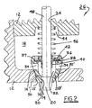
- a two-stage pintle valve 26 having first and second stages 27,29, respectively, in accordance with the invention includes a valve body 12 having a secondary valve seat 14' in a first bore 15 separating first and second chambers 16,18, and a second bore 24 for receiving a pintle as described below connected for reciprocal actuation to a conventional solenoid actuator (not shown).
- a conventional solenoid actuator not shown
- the two-stage valve is operated first with its primary stage alone and then in combination with its secondary stage; the secondary stage cannot be operated without the primary stage.
- the presentation of components is facilitated by presenting herewith the secondary stage before the primary stage.
- a secondary valve head 28' Coaxially disposed within chamber 18 is a secondary valve head 28' having a secondary mating surface 30' opposable to secondary seat 14' for secondary regulation of fluid flow between chambers 16 and 18 across secondary seat 14'.
- Secondary valve head 20' is adapted as follows to contain and form part of a primary valve stage therein.
- Secondary head 20' is provided with a central chamber 32 in communication with chamber 16 via a bore comprising a primary valve seat 14 and with chamber 18 via one or more radial bores 34.
- Chamber 32 further is stepped to form an annular shoulder 36 for receiving a shaft stop washer 38 having an axially-extending cylindrical flange 40.
- An optional spring stop washer 42 also flanged, is included in the preferred embodiment.
- Head 20' is provided with a cylindrical flange 37 surrounding shoulder 36, which flange is rolled or crimped inwards during valve assembly, as shown in FIG. 2, to centrally position and immovably retain washers 38,42 within head 20'.
- a well 44 in body 12 is receivable of one end of a partially-compressed coil spring 46, the opposite end being received by spring stop washer 42.
- a valve pintle 48 is axially and slidably disposed through second bore 24, spring 46, spring stop washer 42, shaft stop washer 38, and chamber 32, and terminates in a primary valve head 20 having a primary mating surface 30 opposable to primary seat 14 for primary regulation of fluid flow between chambers 16 and 18 across primary seat 14 and via radial bores 34 in secondary head 20'.
- Primary head 20 is provided with an axial shoulder 50 having a diameter greater than the diameter of pintle 48 and flange 40. The distance between shoulder 50 and flange 40 governs the extent of removal of surface 30 from seat 14 and therefore the total open area of the primary valve.
- shaft stop washer 38 preferably is formed of a lubricious material, for example, brass, to minimize friction with pintle 48.
- Washer 38 may act as a bearing or guide for pintle 48 and therefore has a close diametrical tolerance to the pintle.
- Spring stop washer 42 which guides the action of the spring and prevents contact of the spring with the pintle, may be formed of the same or different material as washer 38.
- the bore of washer 42 is slightly larger than the bore of washer 38.
- washer 38 is captured within secondary head 20', continued axial retraction of pintle 48, overcoming the spring force of spring 46, causes secondary surface 30' on secondary head 20' to be withdrawn axially from secondary seat 14', thereby permitting secondary flow between chambers 16 and 18 across seat 14' in addition to the primary flow through bores 34.
- Head 20' may be withdrawn as far as may be desired for a particular application; as shown in FIG. 4, head 20' may be withdrawn until flange 37 engages surface 52 of body 12, spring 46 being compressed into well 44.
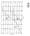
- Typical sigmoid flow curves for the primary and secondary stages as a function of pintle travel are shown as curves 54 and 56, respectively, in FIG. 5.
- the distance between shoulder 50 and flange 40 being approximately 2.5mm, the secondary valve begins to open with pintle travel beyond that point.
- the primary and secondary flows shown in curves 54 and 56 are added together as a total flow, shown in curve 58 which is an extension of primary curve 54.
- FIG. 5 A prior art single-stage valve, such as valve 10 in FIG. 1, is capable of metering flow only over a limited flow range, such as is indicated by curve 54 or curve 56, depending upon the actual size of the valve.
- a smaller valve within the metering head of a larger valve and operating both valves sequentially with a single pintle and actuator, as shown in FIG. 2-4, an expanded metering range is obtained which is greater than can be obtained with any comparable single-stage valve.
- a three-stage pintle valve 57 in accordance with the invention is shown in FIG. 7, in which a tertiary stage 59 surrounds the primary and secondary stages 27,29 shown in FIGS. 2-4.
- the tertiary stage 59 is essentially a larger version of the secondary stage disclosed in the two-stage embodiment.
- a valve body 12 is provided with a first bore 15' containing a tertiary seat 14".
- a tertiary mating surface 30" on tertiary metering head 20" is opposable to seat 14".
- the tertiary stage comprises elements analogous to those in the secondary stage: axial bores 34', shaft stop washer 38', spring stop washer 42', flange 40', spring 46', shoulder 36', chamber 32', as well as secondary seat 14'.
- Chamber 32' contains all the elements of the two-stage valve shown in FIGS. 2-4.
- Pintle 48' is configured as shown in FIG. 7 to accommodate springs 46 and 46' and to permit the pintle to operate primary head 20, secondary head 20', and tertiary head 20" sequentially, in an operating sequence which is an obvious extension of the sequence discussed supra regarding the two-stage valve.
- the invention is especially useful in the field of automotive engines, in which it may be desirable to recirculate a portion of the exhaust gases into the intake manifold to reduce the burn temperature of the mix and thus reduce formation of nitrogen and sulfur oxides.
- the invention permits use of an improved, single size, multiple-stage EGR valve on a wide range of engines, each usage being optimized for a specific engine displacement.
- FIG. 6 shows such a valve installed in an internal combustion engine between port 60 in an exhaust manifold 62 and port 64 in an intake manifold 66 to permit exhaust gas recirculation therebetween.
Landscapes
- Engineering & Computer Science (AREA)
- General Engineering & Computer Science (AREA)
- Mechanical Engineering (AREA)
- Chemical & Material Sciences (AREA)
- Combustion & Propulsion (AREA)
- Magnetically Actuated Valves (AREA)
- Multiple-Way Valves (AREA)
Abstract
next-lower flow stage. The heads and seats for the multiple stages are nested concentrically, the progressively lower-flow stages having progressively smaller diameters. All valve heads except the lowest-flow head have axial and radial bores permitting flow therethrough so that flow may be regulated first by actuating the lowest-
flow stage, then by actuating successively higher flow stages. A single pintle shaft 48 connected to a solenoid actuator is adapted to engage each of the valve heads sequentially as the actuator progresses, beginning with the lowest-flow head, thereby
extending incrementally the dynamic range of the valve as each stage is successively engaged.
Description
Claims (7)
- A pintle valve 26,57 having an expanded flow range, said valve comprising a plurality of concentrically-arranged flow stages 27, 29, 59 ranging from highest flow to lowest flow disposed within a common valve body 12 and being actuable sequentially from lowest flow to highest flow by a common pintle 48, 48' extending through said stages and being selectably attachable to at least one of said stages, each of said stages including a valve head, 20, 20', 20" said head for said highest flow stage being matable with a highest flow seat 14, 14', 14" disposed in said valve body, and each of said heads having a mating surface formed on an outer surface thereof opposed to an adjacent valve seat for regulating flow therebetween and, except said head for said lowest flow stage, a valve seat for the next lower flow stage formed on an inner surface thereof opposed to an adjacent mating surface for regulating flow therebetween.
- A pintle valve 26 in accordance with Claim 1 wherein said valve is a two-stage valve.
- A pintle valve 57 in accordance with Claim 1 wherein said valve is a three-stage valve.
- An expanded-range multiple-stage pintle valve 26, comprising:a) a valve body 12 enclosing a first chamber 16 and having a first axial bore 15 connecting said first chamber 16 to a second chamber 18;b) a secondary valve seat 14' disposed within said first axial bore 15;c) a secondary valve head 20' having a secondary mating surface 30' opposable to said secondary valve seat 14' to regulate secondary fluid flow therebetween, said secondary head having an internal chamber 32 therein, said chamber being in communication with said first and second chambers 16, 18 in said valve body 12, said secondary valve head 20' further including a primary valve seat 14 disposed between said internal chamber 32 and said first chamber 16 in said valve body 12, said secondary valve head 20' further including a shaft stop washer 38 disposed coaxially therein;d) a primary valve head 20 disposed within said secondary valve head 20' and having a primary mating surface 30 opposable to said primary valve seat 14 on said secondary valve head 20' to regulate primary fluid flow therebetween through said secondary valve head 20';e) a valve pintle 48 for actuating said primary and secondary valve heads, said pintle being connected at a first end to said primary valve head 20 and extending through said secondary valve head 20' and said valve body 12 for actuation by actuating means; andf) means for engaging and releasing said secondary valve head from said pintle over a portion of the stroke of said pintle actuation.
- A pintle valve 26 in accordance with Claim 4 wherein said engaging means comprises:a) a shoulder 50 on said primary valve head 20 having a diameter greater than the diameter of said pintle 48;b) an axial flange 40 on said shaft stop washer 38 extending towards said shoulder 50;c) spring means compressively disposed coaxially of said pintle 48 between said shaft stop washer 38 and a wall of said first valve chamber for urging said secondary mating surface 30' of said secondary valve head 20' toward said secondary valve seat 14' to maintain said secondary valve in a closed position while said primary valve 20 is being actuated by said pintle 48, said shoulder 50 being engaging of said flange 40 to actuate said secondary valve 20' at a predetermined distance of stroke of said pintle 48.
- An expanded-range pintle valve 26, comprising:a) a valve body 12 having a chamber 18 therein and inlet and outlet means including a secondary flow seat 14';b) secondary valve means disposed within said chamber 18 for regulating flow across said secondary flow seat 14' and including a primary flow seat 14;c) primary valve means disposed within said secondary valve means for regulating flow across said primary flow seat 14 through said secondary valve means;d) pintle means extending through said secondary valve means and attached to a primary valve head 20 in said primary valve means for actuating said primary valve means; ande) means for selectively causing said pintle means to actuate said secondary valve means.
- An expanded-range pintle valve 57, comprising:a) a valve body 12 having a chamber 18 therein and inlet and outlet means including a tertiary flow seat 14";b) tertiary valve means disposed within said chamber for regulating flow across said tertiary flow seat 14" and including a secondary flow seat 14';c) secondary valve means disposed within said tertiary valve means for regulating flow across said secondary flow seat 14' through said tertiary valve means and including a primary flow seat 14;d) primary valve means disposed within said secondary valve means for regulating flow across said primary flow seat 14 through said secondary and tertiary valve means;e) pintle means extending through said tertiary and secondary valve means and attached to a primary valve head 20 in said primary valve means for actuating said primary valve means; andf) means for selectively causing said pintle means to actuate said secondary and tertiary valve means.
Applications Claiming Priority (2)
| Application Number | Priority Date | Filing Date | Title |
|---|---|---|---|
| US18394400P | 2000-02-22 | 2000-02-22 | |
| US183944P | 2000-02-22 |
Publications (2)
| Publication Number | Publication Date |
|---|---|
| EP1128055A2 true EP1128055A2 (en) | 2001-08-29 |
| EP1128055A3 EP1128055A3 (en) | 2002-08-21 |
Family
ID=22674951
Family Applications (1)
| Application Number | Title | Priority Date | Filing Date |
|---|---|---|---|
| EP01200546A Withdrawn EP1128055A3 (en) | 2000-02-22 | 2001-02-16 | Expanded range multiple-stage metering valve |
Country Status (2)
| Country | Link |
|---|---|
| US (1) | US6729351B2 (en) |
| EP (1) | EP1128055A3 (en) |
Cited By (7)
| Publication number | Priority date | Publication date | Assignee | Title |
|---|---|---|---|---|
| WO2004097274A1 (en) * | 2003-04-17 | 2004-11-11 | Saia-Burgess Gmbh Dresden | Gas control and safety valve |
| EP1610046A1 (en) * | 2004-06-21 | 2005-12-28 | Karl Dungs GmbH & Co.KG | Valve device |
| WO2006136064A1 (en) * | 2005-06-19 | 2006-12-28 | Yongbin Dong | A ball sealing method using pushing method and a sealing valve adapted for this process |
| WO2007065776A1 (en) * | 2005-12-08 | 2007-06-14 | Robert Bosch Gmbh | Two-stage valve for controlling fluids |
| EP1806496A1 (en) * | 2006-01-04 | 2007-07-11 | Delphi Technologies, Inc. | A valve for controlling exhaust gas recirculation flow in an engine |
| DE102007007089A1 (en) * | 2007-02-13 | 2008-08-21 | Woco Industrietechnik Gmbh | Exhaust gas aftertreatment valve for internal combustion engine, has valve unit brought in engagement with valve seat in sealed manner, and another movable valve unit actuated by actuator, which displaces valve units to regulating distance |
| WO2010076779A3 (en) * | 2009-01-05 | 2010-09-30 | Madgal Csf Ltd. | High and low range flow valve |
Families Citing this family (29)
| Publication number | Priority date | Publication date | Assignee | Title |
|---|---|---|---|---|
| US7128080B2 (en) * | 1999-08-09 | 2006-10-31 | Allied Healthcare Products, Inc. | Surge prevention device |
| US6910504B2 (en) * | 2002-01-03 | 2005-06-28 | Allied Healthcare Products, Inc. | Surge prevention device |
| US6745794B2 (en) * | 2002-06-07 | 2004-06-08 | Praxair Technology, Inc. | Flow control valve |
| CA2496882C (en) * | 2002-09-06 | 2011-11-01 | 3M Innovative Properties Company | Metering valve for a metered dose inhaler providing consistent delivery |
| PL1791579T3 (en) * | 2004-09-20 | 2009-10-30 | Medela Holding Ag | Membrane pump with bleed valve |
| DE602004012580D1 (en) * | 2004-11-29 | 2008-04-30 | Techspace Aero Sa | Valve with pressure loss fluctuation |
| GB2429262A (en) * | 2005-08-19 | 2007-02-21 | Ford Global Tech Llc | Shut-off valve assembly with main and auxiliary valves |
| US20070075101A1 (en) * | 2005-10-03 | 2007-04-05 | Pepsico, Inc. | Fluid container and dispensing valve therefor |
| US7461642B2 (en) * | 2006-01-13 | 2008-12-09 | Delphi Technologies, Inc. | Rotary-actuated exhaust gas recirculation valve having a seating force attenuator |
| US20080042090A1 (en) * | 2006-08-18 | 2008-02-21 | Restaurant Technologies, Inc. | Piloted solenoid valve assemblies and related methods |
| PL2071217T3 (en) * | 2007-12-11 | 2010-12-31 | Elster Gmbh | Device for blocking and allowing a fluid stream and accompanying method |
| US8113240B2 (en) | 2008-08-01 | 2012-02-14 | Marshall Excelsior Company | Low emission fluid transfer device |
| CN102203480B (en) * | 2008-09-09 | 2013-11-06 | 阿尔特弥斯智能动力有限公司 | valve assembly |
| WO2010141013A1 (en) * | 2009-06-02 | 2010-12-09 | Arne Fridtjof Myran | Universal valve system |
| DE102010006005A1 (en) * | 2010-01-27 | 2011-07-28 | Elopak Systems Ag | Dosing device and dosing method for liquids |
| WO2012020419A1 (en) * | 2010-08-11 | 2012-02-16 | Amrish Chopra | Integrated fluid control system with multiple values |
| JP2014092144A (en) * | 2012-11-07 | 2014-05-19 | Aisan Ind Co Ltd | Exhaust gas reflux valve |
| CN102943910A (en) * | 2012-12-03 | 2013-02-27 | 卓旦春 | Static balance valve |
| JP6143651B2 (en) * | 2013-11-14 | 2017-06-07 | 愛三工業株式会社 | Exhaust gas recirculation valve |
| US9797279B2 (en) * | 2015-02-27 | 2017-10-24 | GM Global Technology Operations LLC | Exhaust valve and an engine assembly including the exhaust valve having a pressure relief apparatus |
| CN107588204B (en) * | 2016-07-08 | 2025-06-13 | 艾默生过程管理(天津)阀门有限公司 | Cascade controllable fluid control valve and valve trim for fluid control valve |
| US11073279B2 (en) * | 2016-08-23 | 2021-07-27 | Fisher Controls International Llc | Multi-cone, multi-stage spray nozzle |
| US10371374B2 (en) * | 2016-08-30 | 2019-08-06 | Fisher Controls International Llc | Multi-cone, multi-stage spray nozzle |
| DE102017212725A1 (en) * | 2017-07-25 | 2019-01-31 | Robert Bosch Gmbh | Proportional valve for controlling a gaseous medium |
| UA126091C2 (en) * | 2017-12-11 | 2022-08-10 | Сіт. С.П.А. | Valve delivery apparatus |
| DE102018121844A1 (en) * | 2018-09-07 | 2020-03-12 | Vaillant Gmbh | Gas valve |
| EP3870473B1 (en) * | 2018-10-26 | 2022-06-01 | Plastic Omnium Advanced Innovation And Research | Valve for controlling a pressure differential |
| JP7337666B2 (en) * | 2019-11-07 | 2023-09-04 | 愛三工業株式会社 | valve device |
| EP4602291A4 (en) * | 2022-10-12 | 2026-03-11 | Globalforce Ip Ltd | IMPROVEMENTS TO OR IN CONNECTION WITH PRESSURE VALVES |
Family Cites Families (20)
| Publication number | Priority date | Publication date | Assignee | Title |
|---|---|---|---|---|
| GB262863A (en) * | 1925-09-17 | 1926-12-17 | William Dederich | Improvements in balanced valves |
| US2360612A (en) * | 1943-05-29 | 1944-10-17 | Oscar H Ludeman | Valve |
| FR1341639A (en) | 1962-09-19 | 1963-11-02 | Rateau Soc | Advanced valve, balanced type |
| FR1341638A (en) * | 1962-09-19 | 1963-11-02 | Rateau Soc | Improvement of the valves or flaps used, in particular, to the adjustment of the admission of steam turbines |
| US3624753A (en) * | 1970-04-27 | 1971-11-30 | Grove Valve & Regulator Co | Two-stage opening valve |
| US3773085A (en) * | 1971-01-14 | 1973-11-20 | Westinghouse Electric Corp | Noise suppressing throttling valve |
| US3881459A (en) * | 1974-02-28 | 1975-05-06 | Werner Gaetcke | Inlet valve for internal combustion engine and method for supplying fuel thereto |
| CA1029277A (en) * | 1974-10-03 | 1978-04-11 | Yarway Corporation | Two-stage control valve |
| JPS521229A (en) * | 1975-06-24 | 1977-01-07 | Toyota Motor Corp | Suction valve having inverse flow prevention mechanism |
| CH594156A5 (en) * | 1975-07-25 | 1977-12-30 | Sulzer Ag | |
| JPS5485422A (en) * | 1977-12-21 | 1979-07-07 | Tokyo Shibaura Electric Co | Valve |
| US4672203A (en) * | 1983-05-20 | 1987-06-09 | Inficon Leybold-Heraeus, Inc. | Two stage valve for use in pressure converter |
| US4901683A (en) * | 1988-05-12 | 1990-02-20 | Huff Reggie D | Vented valve for internal combustion engines |
| US5085179A (en) * | 1989-06-01 | 1992-02-04 | Ingersoll-Rand Company | Double poppet valve apparatus |
| US5172722A (en) | 1990-09-17 | 1992-12-22 | Motoyama Eng. Works, Ltd. | Stop valve for a vacuum apparatus |
| US5357914A (en) * | 1993-08-24 | 1994-10-25 | Acro-Techn Inc. | Vented valve mechanism for internal combustion engines |
| US5460146A (en) * | 1994-01-12 | 1995-10-24 | Robertshaw Controls Company | Solenoid activated exhaust gas recirculation valve |
| FR2727734B1 (en) | 1994-12-06 | 1997-01-17 | Control Valves Sarl | DOUBLE FLOW CONTROL VALVES |
| JP3745427B2 (en) * | 1995-11-14 | 2006-02-15 | Smc株式会社 | Slow exhaust valve for vacuum pressure control |
| US5782215A (en) * | 1997-06-13 | 1998-07-21 | Engelmann; Mark M. | Intake/exhaust valve |
-
2001
- 2001-02-07 US US09/778,571 patent/US6729351B2/en not_active Expired - Fee Related
- 2001-02-16 EP EP01200546A patent/EP1128055A3/en not_active Withdrawn
Cited By (9)
| Publication number | Priority date | Publication date | Assignee | Title |
|---|---|---|---|---|
| WO2004097274A1 (en) * | 2003-04-17 | 2004-11-11 | Saia-Burgess Gmbh Dresden | Gas control and safety valve |
| EP1610046A1 (en) * | 2004-06-21 | 2005-12-28 | Karl Dungs GmbH & Co.KG | Valve device |
| WO2006136064A1 (en) * | 2005-06-19 | 2006-12-28 | Yongbin Dong | A ball sealing method using pushing method and a sealing valve adapted for this process |
| WO2007065776A1 (en) * | 2005-12-08 | 2007-06-14 | Robert Bosch Gmbh | Two-stage valve for controlling fluids |
| CN101326392B (en) * | 2005-12-08 | 2011-03-16 | 罗伯特·博世有限公司 | Two-Stage Valves for Controlling Fluids |
| US7954511B2 (en) | 2005-12-08 | 2011-06-07 | Robert Bosch Gmbh | Two-stage valve for controlling fluids |
| EP1806496A1 (en) * | 2006-01-04 | 2007-07-11 | Delphi Technologies, Inc. | A valve for controlling exhaust gas recirculation flow in an engine |
| DE102007007089A1 (en) * | 2007-02-13 | 2008-08-21 | Woco Industrietechnik Gmbh | Exhaust gas aftertreatment valve for internal combustion engine, has valve unit brought in engagement with valve seat in sealed manner, and another movable valve unit actuated by actuator, which displaces valve units to regulating distance |
| WO2010076779A3 (en) * | 2009-01-05 | 2010-09-30 | Madgal Csf Ltd. | High and low range flow valve |
Also Published As
| Publication number | Publication date |
|---|---|
| US20010032678A1 (en) | 2001-10-25 |
| EP1128055A3 (en) | 2002-08-21 |
| US6729351B2 (en) | 2004-05-04 |
Similar Documents
| Publication | Publication Date | Title |
|---|---|---|
| US6729351B2 (en) | Expanded range multiple-stage metering valve | |
| US5779220A (en) | Linear solenoid actuator for an exhaust gas recirculation valve | |
| CN101725446B (en) | Low noise fuel pump with variable pressure regulation | |
| US8707996B2 (en) | Selector valve for an internal combustion engine | |
| CN107614862B (en) | Hydraulically Actuated Gaseous Fuel Injector | |
| CN102395761B (en) | Variable stroke valve apparatus for internal combustion engines | |
| US7461642B2 (en) | Rotary-actuated exhaust gas recirculation valve having a seating force attenuator | |
| EP0726390B1 (en) | Fuel system | |
| US7469843B2 (en) | Servo valve for controlling an internal combustion engine fuel injector | |
| CA2622882A1 (en) | Valve apparatus for an internal combustion engine | |
| US20030160197A1 (en) | Solenoid-operated valve | |
| WO1998026168A1 (en) | Pressure balanced gas injection valve | |
| US6390078B1 (en) | Two stage concentric EGR valves | |
| US6484705B2 (en) | Pintle valve having an internal flow modifier with self-aligning head | |
| AU4139199A (en) | Electromagnetic valve for gaseous fluids | |
| EP0859176B1 (en) | Exhaust gas recirculation valve with variable flow area | |
| EP3339620B1 (en) | Passive valve for a fuel injector with a tension spring, fuel injector and methods for producing the same | |
| US20030042450A1 (en) | Force-balanced gas control valve | |
| CN111033029B (en) | Metering plate for reducing variation in discharge coefficient between gaseous fuel injectors | |
| US6817592B2 (en) | Electromagnetic valve actuator with soft-seating | |
| US6749174B2 (en) | Exhaust gas recirculation valve having low drag | |
| CN112761825A (en) | Gas injection valve | |
| US20050028798A1 (en) | Exhaust gas recirculation (EGR) module having sensor integrated into cover (ESM) | |
| AU751916B2 (en) | Pressure balanced gas injection valve | |
| GB2429262A (en) | Shut-off valve assembly with main and auxiliary valves |
Legal Events
| Date | Code | Title | Description |
|---|---|---|---|
| PUAI | Public reference made under article 153(3) epc to a published international application that has entered the european phase |
Free format text: ORIGINAL CODE: 0009012 |
|
| AK | Designated contracting states |
Kind code of ref document: A2 Designated state(s): AT BE CH CY DE DK ES FI FR GB GR IE IT LI LU MC NL PT SE TR |
|
| AX | Request for extension of the european patent |
Free format text: AL;LT;LV;MK;RO;SI |
|
| PUAL | Search report despatched |
Free format text: ORIGINAL CODE: 0009013 |
|
| AK | Designated contracting states |
Kind code of ref document: A3 Designated state(s): AT BE CH CY DE DK ES FI FR GB GR IE IT LI LU MC NL PT SE TR |
|
| AX | Request for extension of the european patent |
Free format text: AL;LT;LV;MK;RO;SI |
|
| RIC1 | Information provided on ipc code assigned before grant |
Free format text: 7F 02M 25/07 A, 7F 16K 1/44 B |
|
| 17P | Request for examination filed |
Effective date: 20030221 |
|
| AKX | Designation fees paid |
Designated state(s): DE FR GB |
|
| 17Q | First examination report despatched |
Effective date: 20030703 |
|
| 17Q | First examination report despatched |
Effective date: 20030703 |
|
| GRAP | Despatch of communication of intention to grant a patent |
Free format text: ORIGINAL CODE: EPIDOSNIGR1 |
|
| STAA | Information on the status of an ep patent application or granted ep patent |
Free format text: STATUS: THE APPLICATION IS DEEMED TO BE WITHDRAWN |
|
| 18D | Application deemed to be withdrawn |
Effective date: 20080603 |