EP1127771A2 - Motor-driven transport trolley with differentiated drive - Google Patents
Motor-driven transport trolley with differentiated drive Download PDFInfo
- Publication number
- EP1127771A2 EP1127771A2 EP01102083A EP01102083A EP1127771A2 EP 1127771 A2 EP1127771 A2 EP 1127771A2 EP 01102083 A EP01102083 A EP 01102083A EP 01102083 A EP01102083 A EP 01102083A EP 1127771 A2 EP1127771 A2 EP 1127771A2
- Authority
- EP
- European Patent Office
- Prior art keywords
- wheels
- transport trolley
- motors
- hydraulic motors
- control unit
- Prior art date
- Legal status (The legal status is an assumption and is not a legal conclusion. Google has not performed a legal analysis and makes no representation as to the accuracy of the status listed.)
- Withdrawn
Links
Images

Classifications
-
- B—PERFORMING OPERATIONS; TRANSPORTING
- B62—LAND VEHICLES FOR TRAVELLING OTHERWISE THAN ON RAILS
- B62B—HAND-PROPELLED VEHICLES, e.g. HAND CARTS OR PERAMBULATORS; SLEDGES
- B62B5/00—Accessories or details specially adapted for hand carts
- B62B5/0026—Propulsion aids
- B62B5/0033—Electric motors
- B62B5/0036—Arrangements of motors
- B62B5/005—Detachably mounted motor units
-
- B—PERFORMING OPERATIONS; TRANSPORTING
- B62—LAND VEHICLES FOR TRAVELLING OTHERWISE THAN ON RAILS
- B62B—HAND-PROPELLED VEHICLES, e.g. HAND CARTS OR PERAMBULATORS; SLEDGES
- B62B5/00—Accessories or details specially adapted for hand carts
- B62B5/0026—Propulsion aids
- B62B5/0033—Electric motors
-
- B—PERFORMING OPERATIONS; TRANSPORTING
- B62—LAND VEHICLES FOR TRAVELLING OTHERWISE THAN ON RAILS
- B62B—HAND-PROPELLED VEHICLES, e.g. HAND CARTS OR PERAMBULATORS; SLEDGES
- B62B5/00—Accessories or details specially adapted for hand carts
- B62B5/0026—Propulsion aids
- B62B5/0079—Towing by connecting to another vehicle
Definitions
- This patent concerns the sector of porterage equipment and particularly it concerns trolleys for shifting bulky and heavy objects.
- This patent specifically refers to a new motor-driven transport trolley with differentiated drive on both sides.
- Transport trolleys are already known for voluminous and/or heavy objects. These trolleys comprise two or more groups of broad wheels with small diameter. One of these trolleys is equipped with a rotating horizontal upper platform, on which the object to be transported rests, and a bar for towing and guiding the trolley, while trolleys without a rotating platform are placed at the rear.
- the trolleys composed as described above are towed by hand by a number of persons.
- Some trolleys are equipped with an electric motor which transmits motion to all the wheels of the trolley, in such a way as to make it less tiring to tow the object that is to be transported. Though convenient, these motor-driven trolleys still present certain drawbacks, including the need for powerful motors to start towing the transported object (pickup) and the difficulty of going round bends since, as the motor acts simultaneously on all the wheels, it is not easy to turn the trolley.
- a new type of transport trolley has been designed and implemented, equipped with hydraulic motors which act independently on two or more wheels or groups of wheels placed on the two sides.
- the new transport trolley comprises a frame or bearing structure, two wheels or sets of wheels, one or more pairs of hydraulic motors, a rotating horizontal upper platform and a control unit for the various motors.
- the frame or bearing structure connects and joins the various other parts.
- it has a generally flat shape and the rotating horizontal platform is placed on top.
- This platform can turn with vertical axis in such a way as to allow the changing of the direction of the trolley with respect to the object transported.
- Each of the two wheels or sets of wheels receives motion, independently of the other, from one or more hydraulic motors.
- two or more hydraulic motors serve and move the wheels of a right-hand set and of a left-hand set.
- connection between the hydraulic motor or motors and the corresponding set of wheels may be achieved by means of cogged belts, chains with links or gears so that all the wheels in a set receive exactly the same motion at the same time.
- the control unit oversees and controls the operation of the various motors and is equipped with a push-button panel or a control stick for controlling the movement of the trolley in the various directions.
- This push-button panel or control stick may be connected to the control unit by means of an electric cable, infrared rays or radio waves.
- the fluid pressure pump may be included in the trolley; preferably it may be separate, for example transported on an auxiliary trolley moved by the operator.
- the power may be supplied to the control unit by the mains or by batteries.
- Figure 1 shows a plan view of the new transport trolley
- figure 2 shows an axonometric view of the same transport trolley.
- each set of wheels (2.1, 2.2) is composed of four wheels placed two by two (2.11, 2.12, 2.21, 2.22); each pair of wheels (2.11, 2.12, 2.21, 2,22) is turned by a hydraulic motor (3.11, 3.12, 3.21, 3.22).
- Each hydraulic motor is equipped with suitable connections (4) for the pressure pump (not shown in the figure).
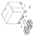
- FIG. 3 shows an interesting compact solution in which the trolley assembly is connected, by means of an extensible bar (5.1), to the control unit (6).
- the extensible bar (5.1) is hinged in point (6.1) to reduce the bulk of the trolley when it is put away.
Abstract
Description
- This patent concerns the sector of porterage equipment and particularly it concerns trolleys for shifting bulky and heavy objects. This patent specifically refers to a new motor-driven transport trolley with differentiated drive on both sides.
- Transport trolleys are already known for voluminous and/or heavy objects. These trolleys comprise two or more groups of broad wheels with small diameter. One of these trolleys is equipped with a rotating horizontal upper platform, on which the object to be transported rests, and a bar for towing and guiding the trolley, while trolleys without a rotating platform are placed at the rear.
- The trolleys composed as described above are towed by hand by a number of persons.
- Some trolleys are equipped with an electric motor which transmits motion to all the wheels of the trolley, in such a way as to make it less tiring to tow the object that is to be transported. Though convenient, these motor-driven trolleys still present certain drawbacks, including the need for powerful motors to start towing the transported object (pickup) and the difficulty of going round bends since, as the motor acts simultaneously on all the wheels, it is not easy to turn the trolley.
- To overcome all the above problems, a new type of transport trolley has been designed and implemented, equipped with hydraulic motors which act independently on two or more wheels or groups of wheels placed on the two sides.
- As regards its main parts, the new transport trolley comprises a frame or bearing structure, two wheels or sets of wheels, one or more pairs of hydraulic motors, a rotating horizontal upper platform and a control unit for the various motors.
- The frame or bearing structure connects and joins the various other parts. In particular it has a generally flat shape and the rotating horizontal platform is placed on top.
- This platform can turn with vertical axis in such a way as to allow the changing of the direction of the trolley with respect to the object transported.
- On each of the two sides of the frame or structure is placed a set of wheels with small diameter and broad width.
- Each of the two wheels or sets of wheels receives motion, independently of the other, from one or more hydraulic motors.
- In other words, two or more hydraulic motors serve and move the wheels of a right-hand set and of a left-hand set.
- The connection between the hydraulic motor or motors and the corresponding set of wheels may be achieved by means of cogged belts, chains with links or gears so that all the wheels in a set receive exactly the same motion at the same time.
- The control unit oversees and controls the operation of the various motors and is equipped with a push-button panel or a control stick for controlling the movement of the trolley in the various directions. This push-button panel or control stick may be connected to the control unit by means of an electric cable, infrared rays or radio waves.
- It is possible to allow for the various hydraulic motors to receive the fluid from a single pressure pump connected to all the motors by means of two or more valves; the pressure differentiation, and therefore the motion differentiation, is consequently determined by the closing or the partial or total opening of the valves. The fluid pressure pump may be included in the trolley; preferably it may be separate, for example transported on an auxiliary trolley moved by the operator.
- This solution offered by the new transport trolley allows each set of wheels, right and left, to be moved independently of the other, that is, by moving the two sets of wheels in a differentiated manner, it is possible to obtain forward and reverse motion and turning of the new transport trolley on the floor without any effort by the operator.
- The power may be supplied to the control unit by the mains or by batteries.
- The following is just an example among many of a practical embodiment of the invention in question, illustrated in the enclosed drawings, wherein:
Figure 1 shows a plan view of the new transport trolley, while figure 2 shows an axonometric view of the same transport trolley. - It is possible to observe the frame or bearing structure (1), the two sets of wheels (2.1, 2.2), the hydraulic motors (3.11, 3.12, 3.21, 3.22) which set the wheels (2.1, 2.2) in motion. In these figures a dashed line indicates the rotating horizontal upper platform (5) on which the object to be transported is placed.
- In these example each set of wheels (2.1, 2.2) is composed of four wheels placed two by two (2.11, 2.12, 2.21, 2.22); each pair of wheels (2.11, 2.12, 2.21, 2,22) is turned by a hydraulic motor (3.11, 3.12, 3.21, 3.22).
- Each hydraulic motor is equipped with suitable connections (4) for the pressure pump (not shown in the figure).
- There is no need for a rigid connection between the control unit and the trolley assembly, since a connection for the passage of the fluid is sufficient.
- Figure 3 shows an interesting compact solution in which the trolley assembly is connected, by means of an extensible bar (5.1), to the control unit (6).
- The extensible bar (5.1) is hinged in point (6.1) to reduce the bulk of the trolley when it is put away.
- These are sufficient schematic indications to allow an expert to implement the invention; consequently, in the tangible application it may be subject to variations without prejudice to the substance of the innovative concept.
- With reference to the above description and to the enclosed drawings, the following claims are therefore put forth.
Claims (3)
- Motor-driven transport trolley comprising a frame with two sets of wheels, right and left, characterized in that it is equipped with two or more hydraulic motors which move the two sets of wheels separately to obtain differentiated drive, and having a rotating plate placed on top.
- Transport trolley according to claim 1, characterized in that the motors are hydraulic and are fed by a pressure pump, and wherein the motion is differently distributed to the various hydraulic motors by means of valves connected to a control unit which controls the operation of the hydraulic motors, the pressure pump and the valves.
- Transport trolley according to claims 1, 2, characterized in that the control unit is controlled by a push-button panel connected to it by means of an electric cable, infrared rays or radio waves, etc.
Applications Claiming Priority (2)
| Application Number | Priority Date | Filing Date | Title |
|---|---|---|---|
| IT2000PD000048A IT1315398B1 (en) | 2000-02-23 | 2000-02-23 | DIFFERENTIATED TRACTION MOTORIZED TRANSPORT TROLLEY |
| ITPD000048 | 2000-06-23 |
Publications (2)
| Publication Number | Publication Date |
|---|---|
| EP1127771A2 true EP1127771A2 (en) | 2001-08-29 |
| EP1127771A3 EP1127771A3 (en) | 2003-06-04 |
Family
ID=11451836
Family Applications (1)
| Application Number | Title | Priority Date | Filing Date |
|---|---|---|---|
| EP01102083A Withdrawn EP1127771A3 (en) | 2000-02-23 | 2001-01-31 | Motor-driven transport trolley with differentiated drive |
Country Status (5)
| Country | Link |
|---|---|
| US (1) | US6662888B2 (en) |
| EP (1) | EP1127771A3 (en) |
| AU (1) | AU1831901A (en) |
| CA (1) | CA2338677A1 (en) |
| IT (1) | IT1315398B1 (en) |
Families Citing this family (5)
| Publication number | Priority date | Publication date | Assignee | Title |
|---|---|---|---|---|
| DE102004021839A1 (en) * | 2004-05-04 | 2005-12-01 | Liebherr-Werk Nenzing Gmbh, Nenzing | Teleladers, especially reachstackers |
| DE102006015772A1 (en) * | 2006-04-04 | 2007-10-11 | Jungheinrich Ag | Truck |
| US7762363B1 (en) * | 2006-12-14 | 2010-07-27 | Hirschfeld Steven L | Motorized beach wagon |
| US8453771B1 (en) | 2006-12-14 | 2013-06-04 | Steven L. Hirschfeld | Beach wagon |
| US11934190B2 (en) * | 2019-08-16 | 2024-03-19 | Sea, Ltd. | Low-profile robotic platform |
Family Cites Families (27)
| Publication number | Priority date | Publication date | Assignee | Title |
|---|---|---|---|---|
| US3828875A (en) * | 1972-12-29 | 1974-08-13 | Continental Oil Co | Hydraulic control apparatus for a mobile slurry handling system |
| US3882885A (en) * | 1973-07-25 | 1975-05-13 | Continental Oil Co | Method of handling a large diameter slurry hose system |
| FR2312229A1 (en) * | 1975-05-29 | 1976-12-24 | Saxby | INSTALLATION FOR THE AUTOMATIC HANDLING OF MANUAL TROLLEYS, ESPECIALLY OF HOSPITAL TROLLEYS |
| US3999623A (en) * | 1975-08-20 | 1976-12-28 | Honeywell Inc. | Frame distortion relief steering control system |
| US4088337A (en) * | 1976-08-19 | 1978-05-09 | Larsen Walter L | Equipment-moving dolly |
| US4137984A (en) * | 1977-11-03 | 1979-02-06 | Jennings Frederick R | Self-guided automatic load transporter |
| DE3418744A1 (en) * | 1984-05-19 | 1985-11-21 | Wolfgang 2820 Bremen Schlott | HEAVY DUTY TROLLEY |
| US4620603A (en) * | 1985-02-19 | 1986-11-04 | Blue Bell, Inc. | Articulated tow vehicle |
| JPS62227819A (en) * | 1986-03-28 | 1987-10-06 | Toyota Autom Loom Works Ltd | Pitching abatement method for skid steering vehicle |
| US5158150A (en) * | 1986-05-13 | 1992-10-27 | Hydra-Powr, Inc. | Hydraulic wheelchair |
| US4697661A (en) * | 1986-07-14 | 1987-10-06 | General Electric Company | Drive design for mobile x-ray units with dual wheel drives |
| US5012879A (en) * | 1990-06-26 | 1991-05-07 | Bienek Richard J | Self-propelled jacking apparatus for factory constructed buildings |
| IT1242083B (en) * | 1990-10-03 | 1994-02-08 | Fiat Auto Spa | ELECTRIC DRIVE VEHICLE WITH EXTERNAL CONTROL PARKING MANEUVER |
| US5181579A (en) * | 1991-04-17 | 1993-01-26 | Trw Inc. | Steering and driving system |
| US5379842A (en) * | 1992-03-30 | 1995-01-10 | Terry; Mel | Material-handling equipment |
| US5355661A (en) * | 1992-05-25 | 1994-10-18 | Kubota Corporation | Lawn mower having a steering handle switchable between a walking mode and a riding mode |
| US5350033A (en) * | 1993-04-26 | 1994-09-27 | Kraft Brett W | Robotic inspection vehicle |
| DE4325703A1 (en) * | 1993-07-30 | 1995-02-02 | Linde Ag | Wheeled vehicle with hydrostatic running gear |
| IT1273230B (en) * | 1994-01-28 | 1997-07-07 | Tagliavini Gianni Ditta Indivi | TROLLEY FOR THE TRANSPORT OF A HIGH WEIGHT MACHINE |
| US5507138A (en) * | 1994-12-16 | 1996-04-16 | Wright Manufacturing Inc. | Power mower with riding platform for supporting standing-operator |
| US5809755A (en) * | 1994-12-16 | 1998-09-22 | Wright Manufacturing, Inc. | Power mower with riding platform for supporting standing operator |
| US5842532A (en) * | 1996-09-25 | 1998-12-01 | Fox American Inc. | Personal transport vehicle and method of improving the maneuverability of a vehicle |
| DE19700909A1 (en) * | 1996-12-27 | 1998-07-02 | Expresso Deutschland | Self-propelled trolley for handicapped driver, for use in libraries |
| FR2764091B1 (en) * | 1997-05-30 | 1999-09-03 | Peugeot | REMOTE CONTROL AND OPERATING DEVICE FOR AT LEAST ONE URBAN VEHICLE, ESPECIALLY ELECTRIC |
| US6076621A (en) * | 1998-05-08 | 2000-06-20 | Spencer Research And Development, Inc. | Mobile work platform |
| DE29910775U1 (en) * | 1999-06-21 | 1999-09-02 | Sbs Sondermaschinen Gmbh | Transport vehicle for heavy loads |
| DE10041578A1 (en) * | 2000-08-24 | 2002-03-21 | Markus Helling | chassis system |
-
2000
- 2000-02-23 IT IT2000PD000048A patent/IT1315398B1/en active
-
2001
- 2001-01-31 EP EP01102083A patent/EP1127771A3/en not_active Withdrawn
- 2001-02-02 US US09/773,630 patent/US6662888B2/en not_active Expired - Fee Related
- 2001-02-06 AU AU18319/01A patent/AU1831901A/en not_active Abandoned
- 2001-02-22 CA CA002338677A patent/CA2338677A1/en not_active Abandoned
Non-Patent Citations (1)
| Title |
|---|
| None |
Also Published As
| Publication number | Publication date |
|---|---|
| EP1127771A3 (en) | 2003-06-04 |
| AU1831901A (en) | 2001-08-30 |
| US6662888B2 (en) | 2003-12-16 |
| CA2338677A1 (en) | 2001-08-23 |
| IT1315398B1 (en) | 2003-02-10 |
| US20010015298A1 (en) | 2001-08-23 |
| ITPD20000048A1 (en) | 2001-08-23 |
Similar Documents
| Publication | Publication Date | Title |
|---|---|---|
| EP0147602B1 (en) | Transportation device | |
| EP1248726B1 (en) | An apparatus for loading and unloading aircrafts | |
| US3942666A (en) | Bale trailer | |
| BE1007895A3 (en) | Device for moving beds. | |
| US7270201B1 (en) | Trailer moving vehicle | |
| US20050164616A1 (en) | Arrangement in a mobile machine for grinding floor surfaces | |
| CA2411296A1 (en) | Vacuum nozzle apparatus | |
| EP1127771A2 (en) | Motor-driven transport trolley with differentiated drive | |
| US6986397B2 (en) | Power riding trailer for an implement | |
| FI81059C (en) | BANDDRIVET TRANSPORTREDSKAP. | |
| US20070289798A1 (en) | Sideloader forklift with all wheel steering | |
| US3147143A (en) | Apparatus for painting, scale removing, traction and so on for massive bodies made of iron plates | |
| US2618396A (en) | Industrial lift-truck apparatus | |
| EP2399803B1 (en) | Lift truck | |
| DE1109441B (en) | Dung removal device | |
| US6050355A (en) | Modular crawler system | |
| US3321180A (en) | Vehicle-moving device having fourposter-type screw jack lifting means | |
| DE102018004094A1 (en) | Electrically operated shopping cart, load cart and suitcase trolley | |
| EP1342867A1 (en) | Automated parking system with movable plattforms for supporting and transporting motor vehicles on previously selected parking positions | |
| US3706110A (en) | Conduit cleaning apparatus | |
| US3049063A (en) | Self propelled earth compactor | |
| DE19648419A1 (en) | Passenger transport device | |
| US3184089A (en) | Fork lift type material handling machine with a laterally adjustable frame | |
| JP2886069B2 (en) | Combine harvesting methods and combine aggregates | |
| JP3540070B2 (en) | Root cropper |
Legal Events
| Date | Code | Title | Description |
|---|---|---|---|
| PUAI | Public reference made under article 153(3) epc to a published international application that has entered the european phase |
Free format text: ORIGINAL CODE: 0009012 |
|
| AK | Designated contracting states |
Kind code of ref document: A2 Designated state(s): AT BE CH CY DE DK ES FI FR GB GR IE IT LI LU MC NL PT SE TR |
|
| AX | Request for extension of the european patent |
Free format text: AL;LT;LV;MK;RO;SI |
|
| PUAL | Search report despatched |
Free format text: ORIGINAL CODE: 0009013 |
|
| AK | Designated contracting states |
Designated state(s): AT BE CH CY DE DK ES FI FR GB GR IE IT LI LU MC NL PT SE TR |
|
| AX | Request for extension of the european patent |
Extension state: AL LT LV MK RO SI |
|
| RIC1 | Information provided on ipc code assigned before grant |
Ipc: 7B 62B 5/00 B Ipc: 7B 62B 3/00 A |
|
| 17P | Request for examination filed |
Effective date: 20031126 |
|
| AKX | Designation fees paid |
Designated state(s): AT BE CH CY DE DK ES FI FR GB GR IE IT LI LU MC NL PT SE TR |
|
| 17Q | First examination report despatched |
Effective date: 20060908 |
|
| STAA | Information on the status of an ep patent application or granted ep patent |
Free format text: STATUS: THE APPLICATION IS DEEMED TO BE WITHDRAWN |
|
| 18D | Application deemed to be withdrawn |
Effective date: 20070320 |