EP1127734A2 - Regeneration control device of hybrid electric vehicle - Google Patents
Regeneration control device of hybrid electric vehicle Download PDFInfo
- Publication number
- EP1127734A2 EP1127734A2 EP01104360A EP01104360A EP1127734A2 EP 1127734 A2 EP1127734 A2 EP 1127734A2 EP 01104360 A EP01104360 A EP 01104360A EP 01104360 A EP01104360 A EP 01104360A EP 1127734 A2 EP1127734 A2 EP 1127734A2
- Authority
- EP
- European Patent Office
- Prior art keywords
- generation
- charging level
- battery
- power consumption
- output generation
- Prior art date
- Legal status (The legal status is an assumption and is not a legal conclusion. Google has not performed a legal analysis and makes no representation as to the accuracy of the status listed.)
- Granted
Links
Images


Classifications
-
- B—PERFORMING OPERATIONS; TRANSPORTING
- B60—VEHICLES IN GENERAL
- B60W—CONJOINT CONTROL OF VEHICLE SUB-UNITS OF DIFFERENT TYPE OR DIFFERENT FUNCTION; CONTROL SYSTEMS SPECIALLY ADAPTED FOR HYBRID VEHICLES; ROAD VEHICLE DRIVE CONTROL SYSTEMS FOR PURPOSES NOT RELATED TO THE CONTROL OF A PARTICULAR SUB-UNIT
- B60W20/00—Control systems specially adapted for hybrid vehicles
-
- B—PERFORMING OPERATIONS; TRANSPORTING
- B60—VEHICLES IN GENERAL
- B60K—ARRANGEMENT OR MOUNTING OF PROPULSION UNITS OR OF TRANSMISSIONS IN VEHICLES; ARRANGEMENT OR MOUNTING OF PLURAL DIVERSE PRIME-MOVERS IN VEHICLES; AUXILIARY DRIVES FOR VEHICLES; INSTRUMENTATION OR DASHBOARDS FOR VEHICLES; ARRANGEMENTS IN CONNECTION WITH COOLING, AIR INTAKE, GAS EXHAUST OR FUEL SUPPLY OF PROPULSION UNITS IN VEHICLES
- B60K6/00—Arrangement or mounting of plural diverse prime-movers for mutual or common propulsion, e.g. hybrid propulsion systems comprising electric motors and internal combustion engines
- B60K6/20—Arrangement or mounting of plural diverse prime-movers for mutual or common propulsion, e.g. hybrid propulsion systems comprising electric motors and internal combustion engines the prime-movers consisting of electric motors and internal combustion engines, e.g. HEVs
- B60K6/42—Arrangement or mounting of plural diverse prime-movers for mutual or common propulsion, e.g. hybrid propulsion systems comprising electric motors and internal combustion engines the prime-movers consisting of electric motors and internal combustion engines, e.g. HEVs characterised by the architecture of the hybrid electric vehicle
- B60K6/46—Series type
-
- B—PERFORMING OPERATIONS; TRANSPORTING
- B60—VEHICLES IN GENERAL
- B60L—PROPULSION OF ELECTRICALLY-PROPELLED VEHICLES; SUPPLYING ELECTRIC POWER FOR AUXILIARY EQUIPMENT OF ELECTRICALLY-PROPELLED VEHICLES; ELECTRODYNAMIC BRAKE SYSTEMS FOR VEHICLES IN GENERAL; MAGNETIC SUSPENSION OR LEVITATION FOR VEHICLES; MONITORING OPERATING VARIABLES OF ELECTRICALLY-PROPELLED VEHICLES; ELECTRIC SAFETY DEVICES FOR ELECTRICALLY-PROPELLED VEHICLES
- B60L50/00—Electric propulsion with power supplied within the vehicle
- B60L50/50—Electric propulsion with power supplied within the vehicle using propulsion power supplied by batteries or fuel cells
- B60L50/60—Electric propulsion with power supplied within the vehicle using propulsion power supplied by batteries or fuel cells using power supplied by batteries
- B60L50/61—Electric propulsion with power supplied within the vehicle using propulsion power supplied by batteries or fuel cells using power supplied by batteries by batteries charged by engine-driven generators, e.g. series hybrid electric vehicles
-
- B—PERFORMING OPERATIONS; TRANSPORTING
- B60—VEHICLES IN GENERAL
- B60L—PROPULSION OF ELECTRICALLY-PROPELLED VEHICLES; SUPPLYING ELECTRIC POWER FOR AUXILIARY EQUIPMENT OF ELECTRICALLY-PROPELLED VEHICLES; ELECTRODYNAMIC BRAKE SYSTEMS FOR VEHICLES IN GENERAL; MAGNETIC SUSPENSION OR LEVITATION FOR VEHICLES; MONITORING OPERATING VARIABLES OF ELECTRICALLY-PROPELLED VEHICLES; ELECTRIC SAFETY DEVICES FOR ELECTRICALLY-PROPELLED VEHICLES
- B60L50/00—Electric propulsion with power supplied within the vehicle
- B60L50/50—Electric propulsion with power supplied within the vehicle using propulsion power supplied by batteries or fuel cells
- B60L50/60—Electric propulsion with power supplied within the vehicle using propulsion power supplied by batteries or fuel cells using power supplied by batteries
- B60L50/61—Electric propulsion with power supplied within the vehicle using propulsion power supplied by batteries or fuel cells using power supplied by batteries by batteries charged by engine-driven generators, e.g. series hybrid electric vehicles
- B60L50/62—Electric propulsion with power supplied within the vehicle using propulsion power supplied by batteries or fuel cells using power supplied by batteries by batteries charged by engine-driven generators, e.g. series hybrid electric vehicles charged by low-power generators primarily intended to support the batteries, e.g. range extenders
-
- B—PERFORMING OPERATIONS; TRANSPORTING
- B60—VEHICLES IN GENERAL
- B60L—PROPULSION OF ELECTRICALLY-PROPELLED VEHICLES; SUPPLYING ELECTRIC POWER FOR AUXILIARY EQUIPMENT OF ELECTRICALLY-PROPELLED VEHICLES; ELECTRODYNAMIC BRAKE SYSTEMS FOR VEHICLES IN GENERAL; MAGNETIC SUSPENSION OR LEVITATION FOR VEHICLES; MONITORING OPERATING VARIABLES OF ELECTRICALLY-PROPELLED VEHICLES; ELECTRIC SAFETY DEVICES FOR ELECTRICALLY-PROPELLED VEHICLES
- B60L58/00—Methods or circuit arrangements for monitoring or controlling batteries or fuel cells, specially adapted for electric vehicles
- B60L58/10—Methods or circuit arrangements for monitoring or controlling batteries or fuel cells, specially adapted for electric vehicles for monitoring or controlling batteries
- B60L58/12—Methods or circuit arrangements for monitoring or controlling batteries or fuel cells, specially adapted for electric vehicles for monitoring or controlling batteries responding to state of charge [SoC]
- B60L58/15—Preventing overcharging
-
- B—PERFORMING OPERATIONS; TRANSPORTING
- B60—VEHICLES IN GENERAL
- B60W—CONJOINT CONTROL OF VEHICLE SUB-UNITS OF DIFFERENT TYPE OR DIFFERENT FUNCTION; CONTROL SYSTEMS SPECIALLY ADAPTED FOR HYBRID VEHICLES; ROAD VEHICLE DRIVE CONTROL SYSTEMS FOR PURPOSES NOT RELATED TO THE CONTROL OF A PARTICULAR SUB-UNIT
- B60W10/00—Conjoint control of vehicle sub-units of different type or different function
- B60W10/04—Conjoint control of vehicle sub-units of different type or different function including control of propulsion units
- B60W10/06—Conjoint control of vehicle sub-units of different type or different function including control of propulsion units including control of combustion engines
-
- B—PERFORMING OPERATIONS; TRANSPORTING
- B60—VEHICLES IN GENERAL
- B60W—CONJOINT CONTROL OF VEHICLE SUB-UNITS OF DIFFERENT TYPE OR DIFFERENT FUNCTION; CONTROL SYSTEMS SPECIALLY ADAPTED FOR HYBRID VEHICLES; ROAD VEHICLE DRIVE CONTROL SYSTEMS FOR PURPOSES NOT RELATED TO THE CONTROL OF A PARTICULAR SUB-UNIT
- B60W10/00—Conjoint control of vehicle sub-units of different type or different function
- B60W10/04—Conjoint control of vehicle sub-units of different type or different function including control of propulsion units
- B60W10/08—Conjoint control of vehicle sub-units of different type or different function including control of propulsion units including control of electric propulsion units, e.g. motors or generators
-
- B—PERFORMING OPERATIONS; TRANSPORTING
- B60—VEHICLES IN GENERAL
- B60W—CONJOINT CONTROL OF VEHICLE SUB-UNITS OF DIFFERENT TYPE OR DIFFERENT FUNCTION; CONTROL SYSTEMS SPECIALLY ADAPTED FOR HYBRID VEHICLES; ROAD VEHICLE DRIVE CONTROL SYSTEMS FOR PURPOSES NOT RELATED TO THE CONTROL OF A PARTICULAR SUB-UNIT
- B60W10/00—Conjoint control of vehicle sub-units of different type or different function
- B60W10/24—Conjoint control of vehicle sub-units of different type or different function including control of energy storage means
- B60W10/26—Conjoint control of vehicle sub-units of different type or different function including control of energy storage means for electrical energy, e.g. batteries or capacitors
-
- B—PERFORMING OPERATIONS; TRANSPORTING
- B60—VEHICLES IN GENERAL
- B60L—PROPULSION OF ELECTRICALLY-PROPELLED VEHICLES; SUPPLYING ELECTRIC POWER FOR AUXILIARY EQUIPMENT OF ELECTRICALLY-PROPELLED VEHICLES; ELECTRODYNAMIC BRAKE SYSTEMS FOR VEHICLES IN GENERAL; MAGNETIC SUSPENSION OR LEVITATION FOR VEHICLES; MONITORING OPERATING VARIABLES OF ELECTRICALLY-PROPELLED VEHICLES; ELECTRIC SAFETY DEVICES FOR ELECTRICALLY-PROPELLED VEHICLES
- B60L2220/00—Electrical machine types; Structures or applications thereof
- B60L2220/10—Electrical machine types
- B60L2220/12—Induction machines
-
- B—PERFORMING OPERATIONS; TRANSPORTING
- B60—VEHICLES IN GENERAL
- B60L—PROPULSION OF ELECTRICALLY-PROPELLED VEHICLES; SUPPLYING ELECTRIC POWER FOR AUXILIARY EQUIPMENT OF ELECTRICALLY-PROPELLED VEHICLES; ELECTRODYNAMIC BRAKE SYSTEMS FOR VEHICLES IN GENERAL; MAGNETIC SUSPENSION OR LEVITATION FOR VEHICLES; MONITORING OPERATING VARIABLES OF ELECTRICALLY-PROPELLED VEHICLES; ELECTRIC SAFETY DEVICES FOR ELECTRICALLY-PROPELLED VEHICLES
- B60L2220/00—Electrical machine types; Structures or applications thereof
- B60L2220/10—Electrical machine types
- B60L2220/14—Synchronous machines
-
- B—PERFORMING OPERATIONS; TRANSPORTING
- B60—VEHICLES IN GENERAL
- B60L—PROPULSION OF ELECTRICALLY-PROPELLED VEHICLES; SUPPLYING ELECTRIC POWER FOR AUXILIARY EQUIPMENT OF ELECTRICALLY-PROPELLED VEHICLES; ELECTRODYNAMIC BRAKE SYSTEMS FOR VEHICLES IN GENERAL; MAGNETIC SUSPENSION OR LEVITATION FOR VEHICLES; MONITORING OPERATING VARIABLES OF ELECTRICALLY-PROPELLED VEHICLES; ELECTRIC SAFETY DEVICES FOR ELECTRICALLY-PROPELLED VEHICLES
- B60L2240/00—Control parameters of input or output; Target parameters
- B60L2240/40—Drive Train control parameters
- B60L2240/44—Drive Train control parameters related to combustion engines
- B60L2240/441—Speed
-
- B—PERFORMING OPERATIONS; TRANSPORTING
- B60—VEHICLES IN GENERAL
- B60L—PROPULSION OF ELECTRICALLY-PROPELLED VEHICLES; SUPPLYING ELECTRIC POWER FOR AUXILIARY EQUIPMENT OF ELECTRICALLY-PROPELLED VEHICLES; ELECTRODYNAMIC BRAKE SYSTEMS FOR VEHICLES IN GENERAL; MAGNETIC SUSPENSION OR LEVITATION FOR VEHICLES; MONITORING OPERATING VARIABLES OF ELECTRICALLY-PROPELLED VEHICLES; ELECTRIC SAFETY DEVICES FOR ELECTRICALLY-PROPELLED VEHICLES
- B60L2270/00—Problem solutions or means not otherwise provided for
- B60L2270/10—Emission reduction
- B60L2270/14—Emission reduction of noise
- B60L2270/145—Structure borne vibrations
-
- B—PERFORMING OPERATIONS; TRANSPORTING
- B60—VEHICLES IN GENERAL
- B60W—CONJOINT CONTROL OF VEHICLE SUB-UNITS OF DIFFERENT TYPE OR DIFFERENT FUNCTION; CONTROL SYSTEMS SPECIALLY ADAPTED FOR HYBRID VEHICLES; ROAD VEHICLE DRIVE CONTROL SYSTEMS FOR PURPOSES NOT RELATED TO THE CONTROL OF A PARTICULAR SUB-UNIT
- B60W2510/00—Input parameters relating to a particular sub-units
- B60W2510/24—Energy storage means
- B60W2510/242—Energy storage means for electrical energy
- B60W2510/244—Charge state
-
- Y—GENERAL TAGGING OF NEW TECHNOLOGICAL DEVELOPMENTS; GENERAL TAGGING OF CROSS-SECTIONAL TECHNOLOGIES SPANNING OVER SEVERAL SECTIONS OF THE IPC; TECHNICAL SUBJECTS COVERED BY FORMER USPC CROSS-REFERENCE ART COLLECTIONS [XRACs] AND DIGESTS
- Y02—TECHNOLOGIES OR APPLICATIONS FOR MITIGATION OR ADAPTATION AGAINST CLIMATE CHANGE
- Y02T—CLIMATE CHANGE MITIGATION TECHNOLOGIES RELATED TO TRANSPORTATION
- Y02T10/00—Road transport of goods or passengers
- Y02T10/60—Other road transportation technologies with climate change mitigation effect
- Y02T10/62—Hybrid vehicles
-
- Y—GENERAL TAGGING OF NEW TECHNOLOGICAL DEVELOPMENTS; GENERAL TAGGING OF CROSS-SECTIONAL TECHNOLOGIES SPANNING OVER SEVERAL SECTIONS OF THE IPC; TECHNICAL SUBJECTS COVERED BY FORMER USPC CROSS-REFERENCE ART COLLECTIONS [XRACs] AND DIGESTS
- Y02—TECHNOLOGIES OR APPLICATIONS FOR MITIGATION OR ADAPTATION AGAINST CLIMATE CHANGE
- Y02T—CLIMATE CHANGE MITIGATION TECHNOLOGIES RELATED TO TRANSPORTATION
- Y02T10/00—Road transport of goods or passengers
- Y02T10/60—Other road transportation technologies with climate change mitigation effect
- Y02T10/70—Energy storage systems for electromobility, e.g. batteries
-
- Y—GENERAL TAGGING OF NEW TECHNOLOGICAL DEVELOPMENTS; GENERAL TAGGING OF CROSS-SECTIONAL TECHNOLOGIES SPANNING OVER SEVERAL SECTIONS OF THE IPC; TECHNICAL SUBJECTS COVERED BY FORMER USPC CROSS-REFERENCE ART COLLECTIONS [XRACs] AND DIGESTS
- Y02—TECHNOLOGIES OR APPLICATIONS FOR MITIGATION OR ADAPTATION AGAINST CLIMATE CHANGE
- Y02T—CLIMATE CHANGE MITIGATION TECHNOLOGIES RELATED TO TRANSPORTATION
- Y02T10/00—Road transport of goods or passengers
- Y02T10/60—Other road transportation technologies with climate change mitigation effect
- Y02T10/7072—Electromobility specific charging systems or methods for batteries, ultracapacitors, supercapacitors or double-layer capacitors
-
- Y—GENERAL TAGGING OF NEW TECHNOLOGICAL DEVELOPMENTS; GENERAL TAGGING OF CROSS-SECTIONAL TECHNOLOGIES SPANNING OVER SEVERAL SECTIONS OF THE IPC; TECHNICAL SUBJECTS COVERED BY FORMER USPC CROSS-REFERENCE ART COLLECTIONS [XRACs] AND DIGESTS
- Y10—TECHNICAL SUBJECTS COVERED BY FORMER USPC
- Y10S—TECHNICAL SUBJECTS COVERED BY FORMER USPC CROSS-REFERENCE ART COLLECTIONS [XRACs] AND DIGESTS
- Y10S903/00—Hybrid electric vehicles, HEVS
- Y10S903/902—Prime movers comprising electrical and internal combustion motors
- Y10S903/903—Prime movers comprising electrical and internal combustion motors having energy storing means, e.g. battery, capacitor
Definitions
- the present invention generally relates to a hybrid electric vehicle, and more particularly to a generation control technique for a hybrid electric vehicle.
- a series hybrid vehicle that is a vehicle equipped with a motor as a source of driving force for the vehicle and a secondary battery, which supplies power to the motor, that is charged by a generator driven by a relatively-small engine.
- the series hybrid vehicle operates the engine to run the generator in order to charge the battery if a charging level (SOC: state of charge) of the battery is low.
- SOC state of charge
- Japanese Patent Provisional Publication No. 11-103503 discloses changing the generated power of a generator and the charged power of the battery according to the rate of change ⁇ SOC of a battery remaining capacity to thereby stabilize the charge state of the battery.
- the rate of change ⁇ SOC of the battery remaining capacity is sensed.
- the power generated by the generator does not increase until the power of the battery is once used to lower the charging level of the battery. More specifically, the generated power does not increase until a certain period of time has passed from a high output requirement from the motor.
- the deep discharge may deteriorate the charging and discharging efficiency of the battery.
- a hybrid electric vehicle comprising: a battery; a generator being rotated by a driving force of an engine to generate power to charge the battery; a traction motor being run by power of the battery; a required power consumption sensing device for sensing a required power consumption of the traction motor; a charging level sensing device for sensing a charging level of the battery; and a generated power control device that starts a normal output generation by said generator if the charging level sensed by the charging level sensing device is not greater than a generation start value, continues the normal output generation until the charging level reaches a generation end value larger than the generation start value, and performs a high output generation with a higher output than in the normal output generation regardless of the charging level sensed by the charging level sensing device if the required power consumption sensed by the required power consumption sensing device is not less than a set value.
- Fig. 1 is a schematic block diagram showing a series hybrid vehicle, to which a generation control device of a hybrid electric vehicle according to the present invention is applied.
- a generation control device of a hybrid electric vehicle according to the present invention is applied.
- a large vehicle such as an omnibus, which runs at a low speed in a city, can be the series hybrid vehicle.
- the series hybrid vehicle is equipped with a traction motor 10 as a source of driving force.
- the traction motor 10 is electrically connected to a high-voltage secondary battery 12, which is used for running the traction motor 10, through an inverter 14.
- the traction motor 10 is, e.g., an induction motor, but may also be a permanent electromagnet synchronous type motor.
- the traction motor 10 When the vehicle is braked, the traction motor 10 functions as an energy regenerative brake, i.e., a generator that utilizes braking energy. More specifically, when a driver of the vehicle operates a brake (not shown), the traction motor 10 generates a braking force and power at the same time. The generated power is charged in the battery 12.
- the inverter 14 supplies stable power to the traction motor 10 by adjusting a voltage and a current supplied from the battery 12 or a later-described generator 22, or supplies stable power to the battery 12 by adjusting a voltage and a current generated by the traction motor 10.
- a pair of driving wheels WR, WL is connected to a rotary shaft of the traction motor 10 through reduction gears 16 and a differential gear 18.
- the reduction gears 16 do not necessarily have to be provided.
- the battery 12 and the inverter 14 are electrically connected to the generator 22 through the other inverter 20.
- a rotary shaft of the generator 22 is connected to an output shaft of an engine 24, which is an internal combustion engine for generator.
- the generator 22 is, i.e., a permanent electromagnet type generator.
- the inverter 20 is also electrically connected to an auxiliary motor 26, which drives auxiliaries such as an air compressor 27 for an air brake and a power steering pump 28.
- the inverter 20 supplies stable power to the battery 12 or the traction motor 10 by adjusting a voltage and a current generated by the generator 22, or supplies stable power to the auxiliary motor 26 by adjusting the voltage and the current from the battery 12.
- the inverter 20 also has a function of adjusting the voltage and the current from the battery 12 and supplying them to the generator 22.
- a relay fuse 30 is mounted between the battery 12 and the inverters 14, 20.
- the relay fuse 30 is electrically connected to the inverter 14.
- the relay fuse 30 allows a current to flow from the battery 12 to the traction motor 10, prevents an excessive current from flowing from the battery 12 to the traction motor 10 in accordance with information from the inverter 14, prevents the generator 22 or traction motor 10 during the regenerative braking (the engine regeneration) from excessively charging the battery 12.
- the battery 12 and the inverters 14, 20 are electrically connected to an electronic control unit (ECU) 40 so that the battery 12 and the inverter 14, 20 can communicate with the ECU 40.
- the inverter 14 and the inverter 20 are electrically connected to the traction motor 10 and the generator 22, respectively, so that they can communicate with one another.
- the ECU 40 is connected to a battery controller 46, which monitors a charging level (SOC: state of charging), etc. of the battery 12, and an engine controller 48, which controls the operation of the engine 24.
- SOC charging level
- the receiving side of the ECU 40 is connected to an accelerator pedal 50 that transmits one output requirement from a driver to the traction motor 10.
- the receiving side of the ECU 40 is also connected to an acceleration sensor 52 that senses a control input ⁇ acc of the accelerator pedal 50.
- a required power consumption sensing device 41 in the ECU 40 calculates a required power consumption Pm.
- a relationship between the control input ⁇ acc of the accelerator pedal 50 and the required power consumption Pm is preset on a map or the like.
- a required motor torque signal corresponding to the control input ⁇ acc of the accelerator pedal 50 is supplied to the inverter 14 while the vehicle is running.
- the inverter 14 adjusts the voltage and the current from the battery 12, and therefore, the traction motor 10 generates a desired motor torque.
- the battery controller 46 senses a drop in SOC of the battery 12
- the engine controller 48 starts the engine 24 to operate the generator 22, which generates power to charge the battery 12 in accordance with SOC.
- the generator 22 has a normal output generation mode and a high output generation mode as described later in further detail.
- the traction motor 10 performs the regenerative braking and generates power to charge the battery 12. While the vehicle is running, the power from the battery 12 appropriately runs the auxiliary motor 26 in order to drive the auxiliaries such as the compressor 27 and the power steering pump 28.
- the series hybrid type vehicle has the normal output generation mode and the high output generation mode.
- the generation control device of the hybrid type vehicle according to the present invention i.e., the generation control technique for the engine 24.
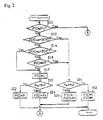
- Figs. 2 and 3 are flow charts showing a generation control routine executed by the ECU 40 according to the present invention (a generation power control device).
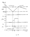
- Fig. 4 is a time chart showing an example of the results of the generation control. Referring to Fig. 4, there will now be described the generation control procedure along the flow charts of Figs. 2 and 3.
- step S10 in Fig. 2 it is determined whether the value of a later-described control flag F (Gm) is 1 or not. Since the initial value of the control flag F (Gm) is 0, the process goes to a step S12. In the step S12, it is determined whether the SOC of the battery 12 is higher than a generation end charging level (a generation end value) SOCend (e.g., 80% of the total SOC). If NO, i.e., the SOC is determined as being not greater than the generation end charging level SOCend, the process goes to a step S14.
- a generation end charging level e.g., 80% of the total SOC
- step S14 it is determined whether the SOC is lower than a generation start charging level (a generation start value) SOCsta (e.g., 75% of the total SOC). If YES, i.e., the SOC is determined as being lower than the generation start charging level SOCsta (a timing tl in Fig. 4), the process goes to a step S18. If the SOC is determined as being lower than the generation start charging level SOCsta, it can be considered that it is necessary to charge the battery 12, i.e., it is necessary for the generator 22 to generate the power. Therefore, in the step S18, a generation flag F (G) is set at 1 to memorize that the generator 22 generates the power.
- a generation start charging level e.g., 75% of the total SOC.
- a required power consumption (Pm) of the traction motor 10 is larger than a set value Ph or not. In other words, it is determined whether the power required for the traction motor 10 is large or not because, e.g., the vehicle is running or is rapidly accelerating on a slope. If NO, i.e., the required power consumption Pm is determined as being not greater than the set value Ph, in other words, if the traction motor does not require a large quantity of power as in the case where the vehicle is normally running on a flat road, the process goes to a step S22.
- Pm required power consumption
- the generator 22 In the step S22, the generator 22 generates the power while the engine 24 is controlled so that a generated power quantity P (G) can be a predetermined power value P1 corresponding to a normal output generation (timings tl-t2 in Fig. 4). More specifically, if the required power consumption Pm of the traction motor 10 is not greater than the set value Ph, the power is generated with a normal output. If the normal output generation is executed, the charging in the battery 12 proceeds so that the SOC can increase to reach the generation start charging level SOCsta. If the SOC reaches the generation start charging level SOCsta, the determination result of the step S14 is NO. The process then goes to a step S16.
- step S20 If the determination result in the step S20 is NO and the required power consumption Pm of the traction motor 10 is still not greater than Ph, the normal output generation is continued. On the other hand, the process goes to the step S24 if the power required for the traction motor 10 is rapidly increased and the determination result in the step S20 is YES, i.e., the required power consumption Pm is determined as being not less than the set value Ph.
- the generator 22 generates the power while the engine 24 is controlled so that the generated power P (G) can be a predetermined power value P2 corresponding to the high output generation with a higher output than the normal output generation (a timing t2 in Fig. 4). More specifically, if the required power consumption Pm of the traction motor 10 is larger than the set value Ph, the high output generation is executed so that the battery 12 can be charged rapidly with an excellent responsiveness.
- step S26 On the start of the high output generation, the process goes to a step S26 in Fig. 3.
- the control flag F (Gm) is set at 1 to memorize the fact that the high output generation is being executed. Then, the process goes to a step S28.
- step S28 whether the SOC exceeds the generation end charging level SOCend or not is determined according to the increase in the SOC. If no, i.e., it is determined that the SOC is still not greater than the generation end completion level SOCend, the determination result is YES next time the routine is executed since the control flag F (Gm) is set at 1 in the step S10. In this case, the process goes to a step S32 to continue the high output generation with the generated power P (G) being maintained at a predetermined power value P2 (timings t2-t3 in Fig. 4).
- step S28 determines whether the generation end charging level SOCend. If the determination result in the step S28 is YES and the SOC is determined as being in excess of the generation end charging level SOCend, it is unnecessary to charge the battery 12. Thus, the engine 24 is stopped so that the generator 22 can end the high output generation.
- the control flag F (Gm) at 0 to memorize the end of the high output generation (a timing t3 in Fig. 4).
- the high output generation is continued until the SOC reaches the generation end charging level SOCend even if the required power consumption Pm is decreased to the set value Ph. More specifically, whether to stop the high output generation is determined according to the SOC. This prevents hunting of the high output generation and the normal output generation and charges the battery 12 more rapidly than in the normal output generation even if the required power consumption Pm is changed across the set value Ph.
- the determination result in the step S12 is YES the next time when the routine is executed.
- the process then goes to a step S34.
- step S34 it is determined in the step S34 whether the required power consumption Pm is larger than the set value Ph.
- the process goes to a step S28 if the determination result is NO, i.e., the required power consumption Pm is determined as being not greater than the set value Ph, in other words, the traction motor 10 does not require a large quantity of power. If the required power consumption Pm is not greater than the set value Ph, it can be considered that the SOC does not decrease rapidly.
- the generation flag F(G) is set at 0 to memorize the fact that the generator 22 does not generate power. Accordingly, the generated power P(G) is set at 0.
- step S34 If the determination result in the step S34 is YES, i.e., the required power consumption Pm is determined as being greater than the set value Ph, the process goes to a step S36. If the required power consumption Pm is larger than the set value Ph, it can be considered that the power of the battery 12 is consumed rapidly. Thus, in the step S36, the high output generation is executed even if the SOC is in excess of the generation end charging level SOCend and the SOC is currently decreasing. This prevents the deep discharge, i.e., the rapid discharge of the battery 12 to desirably maintain the SOC of the battery 12 even if the power of the battery 12 is rapidly consumed.
- the steps S26 through S32 are executed as stated previously. Therefore, while the SOC is decreasing, the high output generation continues until the SOC reaches the generation end charging level SOCend. Even if the require power consumption Pm is changed across the set value Ph, the hunting of the high output generation and the normal output generation can be prevented and the battery can be charged more rapidly than in the normal output generation.
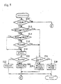
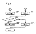
- Figs. 5 and 6 are flow charts showing a control routine according to another embodiment of the present invention. A description will hereunder be given with reference to the flow charts. According to the present embodiment, the generation is controlled basically in the same manner as the above-described embodiment. A description will hereunder be given of parts different from those in Figs. 2 and 3, i.e., parts related to steps S10', S26' through S30' denoted by the same reference numerals as those in Figs. 2 and 3.
- the process goes to a step S26' in Fig. 6 when the high output generation is started in the step S24 or S36 in Fig. 5.
- the control flag F(Gt) at 1 to memorize the fact that the high output generation is currently executed.
- the process then goes to a step S28'.
- step S28' If the determination result in the step S28' is YES and the elapsed time is determined as being in excess of the predetermined time Tg, it is no more necessary to charge the battery 12. Thus, the engine 24 is stopped to cause the generator 22 to end the high output generation.
- the control flag F(Gt) is set at 0 to memorize the end of the high output generation, and the elapsed time Tc is reset at 0 at the same time.
- the high output generation continues until the elapsed time Tc reaches the predetermined time Tg even if the required power consumption Pm becomes not greater than the set value Ph.
- whether the high output generation should be stopped or not is determined according to the elapsed time Tc. This prevents the hunting of the high output generation and the normal output generation and charges the battery 12 more rapidly than in the normal output generation even if the require power consumption Pm is changed across the set value Ph as is the case with the previously-described embodiment.
- the elapsed time Tc is counted from the start of the high output generation, but the present invention should not be restricted to this.
- the elapsed time Tc may be counted up from a point where the require power consumption Pm becomes smaller than the set value Ph after the start of the high output generation, and the high output generation may be ended when the elapsed time Tc reaches the predetermined time Tg.
- there are the normal output generation mode and the high output generation mode and the generated power P(G) is switched between the predetermined power value P1 and the predetermined power value P2 according to the required power consumption Pm.
- the present invention should not be restricted to this.
- the generated power P(G) may be changed at multiple stages or linearly according to the required power consumption Pm. This realizes a more precise control of the generation.
- the required power consumption Pm is found from the output of the acceleration sensor 52, but the present invention should not be restricted to this.
- the inverter 24 may sense the actual power consumption of the motor and utilize the sensed power consumption as the required power consumption.
Landscapes
- Engineering & Computer Science (AREA)
- Transportation (AREA)
- Mechanical Engineering (AREA)
- Chemical & Material Sciences (AREA)
- Combustion & Propulsion (AREA)
- Life Sciences & Earth Sciences (AREA)
- Sustainable Development (AREA)
- Sustainable Energy (AREA)
- Power Engineering (AREA)
- Automation & Control Theory (AREA)
- Electric Propulsion And Braking For Vehicles (AREA)
- Hybrid Electric Vehicles (AREA)
Abstract
Description
Claims (6)
- A hybrid electric vehicle comprising:a battery;a generator being rotated by driving force of an engine to generate power and charge said battery;a traction motor being run by power of said battery;a required power consumption sensing device for sensing a required power consumption for said traction motor;a charging level sensing device for sensing a charging level of said battery;a generated power control device which starts a normal output generation by said generator if the charging level sensed by said charging level sensing device is not greater than a generation start value, and continues said normal output generation until the charging level reaches a generation end value larger than said generation start value, and which performs a high output generation with a higher output than in said normal output generation regardless of the charging level sensed by said charging level sensing device if the required power consumption sensed by said required power consumption sensing device is not less than a set value.
- A hybrid electric vehicle according to claim 1, wherein:
said generated power control device continues said high output generation until the charging level sensed by said charging level sensing device reaches said generation end value. - A hybrid electric vehicle according to claim 1, wherein
said generated power control device continues said high output generation for a predetermined time after said high output generation starts. - A hybrid electric vehicle according to claim 1, wherein:
said generated power control device continues said high output generation for a predetermined time after said required power consumption becomes smaller than a set value. - A hybrid electric vehicle according to claim 1, wherein:
said generated power control device executes said high output generation correspondingly to the required power consumption sensed by said required power consumption sensing device. - A hybrid electric vehicle comprising:a battery;a generator being rotated by driving force of an engine to generate power and charge said battery;a traction motor being run by power of said battery;a required power consumption sensing device for sensing a required power consumption for said traction motor;a charging level sensing device for sensing a charging level of said battery;a generated power control device for executing a normal output generation mode in which said generator performs a normal output generation if the charging level sensed by said charging level sensing device is not greater than a generation start value, or a high output generation mode in which said generator performs a high output generation with a higher output than in said normal output generation regardless of the charging level sensed by said charging level sensing device if the required power consumption sensed by said required power consumption sensing device is not less than a set value.
Applications Claiming Priority (2)
| Application Number | Priority Date | Filing Date | Title |
|---|---|---|---|
| JP2000047433A JP3912475B2 (en) | 2000-02-24 | 2000-02-24 | Power generation control device for hybrid electric vehicle |
| JP2000047433 | 2000-02-24 |
Publications (3)
| Publication Number | Publication Date |
|---|---|
| EP1127734A2 true EP1127734A2 (en) | 2001-08-29 |
| EP1127734A3 EP1127734A3 (en) | 2002-04-24 |
| EP1127734B1 EP1127734B1 (en) | 2004-05-06 |
Family
ID=18569683
Family Applications (1)
| Application Number | Title | Priority Date | Filing Date |
|---|---|---|---|
| EP01104360A Expired - Lifetime EP1127734B1 (en) | 2000-02-24 | 2001-02-23 | Regeneration control device of hybrid electric vehicle |
Country Status (4)
| Country | Link |
|---|---|
| US (1) | US6429613B2 (en) |
| EP (1) | EP1127734B1 (en) |
| JP (1) | JP3912475B2 (en) |
| DE (1) | DE60103093T2 (en) |
Cited By (5)
| Publication number | Priority date | Publication date | Assignee | Title |
|---|---|---|---|---|
| FR2841835A1 (en) * | 2002-07-08 | 2004-01-09 | Toyota Motor Co Ltd | VEHICLE CONTROL APPARATUS AND VEHICLE CONTROL METHOD |
| FR2842470A1 (en) * | 2002-07-19 | 2004-01-23 | Renault Sa | ENERGY RESOURCES MANAGEMENT METHOD FOR HYBRID SERIES VEHICLE |
| WO2013059667A1 (en) | 2011-10-21 | 2013-04-25 | Fisker Automotive, Inc. | Systems and methods for controlling operation of a vehicle |
| CN103204072A (en) * | 2013-04-17 | 2013-07-17 | 奇瑞汽车股份有限公司 | Vehicle controller |
| DE102004035525B4 (en) * | 2003-07-22 | 2017-05-24 | Honda Motor Co., Ltd. | working machine |
Families Citing this family (41)
| Publication number | Priority date | Publication date | Assignee | Title |
|---|---|---|---|---|
| US6766874B2 (en) * | 1998-09-29 | 2004-07-27 | Hitachi, Ltd. | System for driving hybrid vehicle, method thereof and electric power supply system therefor |
| EP1193825B1 (en) * | 2000-09-28 | 2004-10-20 | Denso Corporation | Vehicle-mounted device control system |
| US6622804B2 (en) * | 2001-01-19 | 2003-09-23 | Transportation Techniques, Llc. | Hybrid electric vehicle and method of selectively operating the hybrid electric vehicle |
| US20020163198A1 (en) * | 2001-05-03 | 2002-11-07 | Gee Thomas Scott | Fail-safe engine cooling control algorithm for hybrid electric vehicle |
| JP3826749B2 (en) * | 2001-08-22 | 2006-09-27 | 株式会社日立製作所 | Power converter with shunt resistor |
| JP2004222413A (en) * | 2003-01-15 | 2004-08-05 | Honda Motor Co Ltd | Control device for hybrid vehicle |
| US6994360B2 (en) * | 2003-09-22 | 2006-02-07 | Ford Global Technologies, Llc | Controller and control method for a hybrid electric vehicle powertrain |
| KR100588500B1 (en) * | 2003-09-24 | 2006-06-13 | 현대자동차주식회사 | 4-wheel drive system using motor and its control method |
| US6876098B1 (en) | 2003-09-25 | 2005-04-05 | The United States Of America As Represented By The Administrator Of The Environmental Protection Agency | Methods of operating a series hybrid vehicle |
| US20050205313A1 (en) * | 2004-03-19 | 2005-09-22 | Gilmore Curt D | Hybrid vehicle with power assisted prop shaft |
| JP2005278251A (en) * | 2004-03-23 | 2005-10-06 | Fuji Heavy Ind Ltd | Power generation control device for hybrid vehicle |
| JP2006094689A (en) * | 2004-08-25 | 2006-04-06 | Toyota Motor Corp | Electric vehicle and control method thereof |
| WO2006039520A1 (en) * | 2004-09-30 | 2006-04-13 | Mtd Products Inc. | Hybrid utility vehicle |
| US7332881B2 (en) | 2004-10-28 | 2008-02-19 | Textron Inc. | AC drive system for electrically operated vehicle |
| DE102004055128A1 (en) * | 2004-11-16 | 2006-06-01 | Volkswagen Ag | Method for controlling an operation of a hybrid motor vehicle and hybrid vehicle |
| US8373381B2 (en) * | 2005-04-22 | 2013-02-12 | GM Global Technology Operations LLC | DC/DC-less coupling of matched batteries to fuel cells |
| JP4325598B2 (en) * | 2005-08-08 | 2009-09-02 | 株式会社デンソー | Power generation control device for internal combustion engine |
| JP4830462B2 (en) * | 2005-11-18 | 2011-12-07 | トヨタ自動車株式会社 | Control device for electric vehicle |
| DE102006005477B4 (en) * | 2006-02-03 | 2007-10-11 | Veit Wilhelm | Apparatus for generating electricity, and motor vehicle with electric drive and such device |
| JP5001566B2 (en) * | 2006-03-23 | 2012-08-15 | 三菱ふそうトラック・バス株式会社 | Electric vehicle control device |
| US7859202B2 (en) * | 2007-03-09 | 2010-12-28 | Illinois Institute Of Technology | Power management for multi-module energy storage systems in electric, hybrid electric, and fuel cell vehicles |
| JP5036416B2 (en) * | 2007-06-15 | 2012-09-26 | トヨタ自動車株式会社 | Power supply system, vehicle equipped with the same, and charge / discharge control method |
| US8403086B1 (en) * | 2007-10-05 | 2013-03-26 | Leonard Michael Free | System, method and apparatus for supplying supplemental power to an electric vehicle |
| US7926889B2 (en) | 2007-10-29 | 2011-04-19 | Textron Innovations Inc. | Hill hold for an electric vehicle |
| US8217631B2 (en) * | 2008-01-22 | 2012-07-10 | Honda Motor Co., Ltd. | ACG output voltage control |
| US8334679B2 (en) * | 2008-01-22 | 2012-12-18 | Honda Motor Co., Ltd. | ACG output voltage control |
| JP4662566B2 (en) * | 2008-04-04 | 2011-03-30 | 本田技研工業株式会社 | Control device for hybrid vehicle |
| JP2009286254A (en) * | 2008-05-29 | 2009-12-10 | Denso Corp | In-vehicle device and program |
| US20100181126A1 (en) * | 2009-01-16 | 2010-07-22 | Penrod Fred F | Electric car battery charging system |
| JP5305025B2 (en) * | 2009-07-06 | 2013-10-02 | スズキ株式会社 | Hybrid vehicle |
| US8981589B2 (en) | 2010-08-24 | 2015-03-17 | GM Global Technology Operations LLC | Switched battery and capacitor arrangement and related operating methods |
| US9030063B2 (en) | 2010-12-17 | 2015-05-12 | Tesla Motors, Inc. | Thermal management system for use with an integrated motor assembly |
| RU2013135287A (en) * | 2010-12-27 | 2015-02-10 | Хонда Мотор Ко., Лтд. | DEVICE FOR MANAGEMENT OF GENERATION AND METHOD OF MANAGEMENT OF GENERATION |
| US9393876B2 (en) | 2010-12-27 | 2016-07-19 | Honda Motor Co., Ltd | Generation control apparatus and generation control method |
| CN102717722B (en) * | 2012-06-01 | 2015-05-20 | 北京航空航天大学 | Auxiliary power unit for electric vehicle |
| AU2012385593B2 (en) * | 2012-07-20 | 2016-02-25 | Mitsubishi Electric Corporation | Hybrid vehicle control device |
| US8800698B1 (en) * | 2013-06-28 | 2014-08-12 | Nasser Fred Mehr | LNG—lithium hybrid vehicle (LLHV) |
| WO2015029507A1 (en) | 2013-08-29 | 2015-03-05 | 本田技研工業株式会社 | Electricity-generation control device and electricity-generation control method |
| JP7155930B2 (en) | 2018-11-20 | 2022-10-19 | トヨタ自動車株式会社 | Hybrid vehicle control system |
| KR102648822B1 (en) * | 2019-04-24 | 2024-03-19 | 현대자동차주식회사 | SOC control method and apparatus for improving fuel efficiency of hybrid vehicle |
| USD1101584S1 (en) * | 2023-07-28 | 2025-11-11 | Consumer Safety Technology, Llc | Personal tester |
Family Cites Families (22)
| Publication number | Priority date | Publication date | Assignee | Title |
|---|---|---|---|---|
| JP2932607B2 (en) | 1990-05-23 | 1999-08-09 | 日産自動車株式会社 | Electric car |
| AU666187B2 (en) * | 1992-05-15 | 1996-02-01 | Mitsubishi Jidosha Kogyo Kabushiki Kaisha | Operating method for a hybrid car |
| JP3049980B2 (en) | 1992-12-21 | 2000-06-05 | トヨタ自動車株式会社 | Control device for engine drive generator for electric vehicle |
| JP3094745B2 (en) | 1993-09-24 | 2000-10-03 | トヨタ自動車株式会社 | Hybrid vehicle power generation control device |
| JP3175431B2 (en) * | 1993-10-15 | 2001-06-11 | トヨタ自動車株式会社 | Power generation control device for hybrid electric vehicle |
| JP3094772B2 (en) * | 1994-02-21 | 2000-10-03 | トヨタ自動車株式会社 | Generator output control device of an electric vehicle equipped with a generator |
| JPH0898305A (en) * | 1994-09-29 | 1996-04-12 | Seiko Epson Corp | Travelling device of electric car |
| US5619417A (en) * | 1994-11-23 | 1997-04-08 | Chrysler Corporation | Battery monitoring system for an electric vehicle |
| JP3230406B2 (en) * | 1995-03-10 | 2001-11-19 | 三菱自動車工業株式会社 | Electric vehicle regenerative control device |
| JP3286492B2 (en) * | 1995-04-28 | 2002-05-27 | 本田技研工業株式会社 | Control device for on-board power generator |
| JP3052803B2 (en) * | 1995-05-19 | 2000-06-19 | トヨタ自動車株式会社 | Power transmission device and control method thereof |
| US6116363A (en) * | 1995-05-31 | 2000-09-12 | Frank Transportation Technology, Llc | Fuel consumption control for charge depletion hybrid electric vehicles |
| JP3256657B2 (en) * | 1996-04-10 | 2002-02-12 | 本田技研工業株式会社 | Hybrid vehicle control device |
| CA2182630C (en) * | 1996-08-02 | 2003-02-11 | Piotr Drozdz | A control system for a hybrid vehicle |
| JPH10178703A (en) * | 1996-12-20 | 1998-06-30 | Toyota Motor Corp | Power generation control device for hybrid electric vehicle |
| JP3767103B2 (en) * | 1997-07-16 | 2006-04-19 | 日産自動車株式会社 | Electric vehicle control device |
| JP3685920B2 (en) * | 1997-09-14 | 2005-08-24 | 本田技研工業株式会社 | Electric motor controller for hybrid vehicles |
| JP3409661B2 (en) | 1997-09-29 | 2003-05-26 | 日産自動車株式会社 | Control device for hybrid vehicle |
| JPH11136808A (en) * | 1997-10-31 | 1999-05-21 | Nissan Motor Co Ltd | Power generation control device for hybrid vehicle |
| US5941328A (en) * | 1997-11-21 | 1999-08-24 | Lockheed Martin Corporation | Electric vehicle with variable efficiency regenerative braking depending upon battery charge state |
| JP3536634B2 (en) * | 1997-12-25 | 2004-06-14 | 日産自動車株式会社 | Hybrid vehicle control device |
| JP2001238303A (en) * | 2000-02-24 | 2001-08-31 | Mitsubishi Motors Corp | Regenerative controller for hybrid electric vehicle |
-
2000
- 2000-02-24 JP JP2000047433A patent/JP3912475B2/en not_active Expired - Fee Related
-
2001
- 2001-02-23 DE DE60103093T patent/DE60103093T2/en not_active Expired - Fee Related
- 2001-02-23 US US09/790,659 patent/US6429613B2/en not_active Expired - Fee Related
- 2001-02-23 EP EP01104360A patent/EP1127734B1/en not_active Expired - Lifetime
Cited By (9)
| Publication number | Priority date | Publication date | Assignee | Title |
|---|---|---|---|---|
| FR2841835A1 (en) * | 2002-07-08 | 2004-01-09 | Toyota Motor Co Ltd | VEHICLE CONTROL APPARATUS AND VEHICLE CONTROL METHOD |
| US7463958B2 (en) | 2002-07-08 | 2008-12-09 | Toyota Jidosha Kabushiki Kaisha | Vehicle control apparatus and vehicle control method |
| FR2842470A1 (en) * | 2002-07-19 | 2004-01-23 | Renault Sa | ENERGY RESOURCES MANAGEMENT METHOD FOR HYBRID SERIES VEHICLE |
| WO2004009395A3 (en) * | 2002-07-19 | 2004-04-08 | Renault Sa | Method for managing energy resources for a series hybrid vehicle |
| DE102004035525B4 (en) * | 2003-07-22 | 2017-05-24 | Honda Motor Co., Ltd. | working machine |
| WO2013059667A1 (en) | 2011-10-21 | 2013-04-25 | Fisker Automotive, Inc. | Systems and methods for controlling operation of a vehicle |
| EP2768707A4 (en) * | 2011-10-21 | 2017-05-03 | Karma Automotive LLC | Systems and methods for controlling operation of a vehicle |
| CN103204072A (en) * | 2013-04-17 | 2013-07-17 | 奇瑞汽车股份有限公司 | Vehicle controller |
| CN103204072B (en) * | 2013-04-17 | 2015-07-15 | 奇瑞汽车股份有限公司 | Vehicle controller |
Also Published As
| Publication number | Publication date |
|---|---|
| US20010020833A1 (en) | 2001-09-13 |
| US6429613B2 (en) | 2002-08-06 |
| DE60103093D1 (en) | 2004-06-09 |
| EP1127734B1 (en) | 2004-05-06 |
| JP3912475B2 (en) | 2007-05-09 |
| JP2001238304A (en) | 2001-08-31 |
| EP1127734A3 (en) | 2002-04-24 |
| DE60103093T2 (en) | 2005-06-16 |
Similar Documents
| Publication | Publication Date | Title |
|---|---|---|
| EP1127734B1 (en) | Regeneration control device of hybrid electric vehicle | |
| EP1129889A2 (en) | Regeneration control device of hybrid electric vehicle | |
| US5495906A (en) | Controller of hybrid electric vehicle | |
| US7034482B2 (en) | Regeneration control for hybrid vehicle | |
| US7015676B2 (en) | Battery control apparatus | |
| US6314346B1 (en) | Control system for hybrid vehicle | |
| KR101085506B1 (en) | Hybrid vehicle control unit and hybrid vehicle | |
| US7296648B2 (en) | Power control apparatus for hybrid vehicle | |
| CN1629006B (en) | Vehicle drive control device | |
| US6262491B1 (en) | Control system for hybrid vehicle | |
| JPH0998515A (en) | Hybrid vehicle engine control system | |
| JP2004048819A (en) | Vehicle controller | |
| JP5691919B2 (en) | Vehicle power control device | |
| CN107264516A (en) | The running driving device of vehicle | |
| CN107264259A (en) | Travel drive equipment for vehicles | |
| US7308958B2 (en) | Method for controlling a series hybrid electric vehicle | |
| JP3094701B2 (en) | Control device for engine drive generator for electric vehicle | |
| JP3429068B2 (en) | Hybrid powered electric vehicle | |
| JP2006312352A (en) | Control device for drive system | |
| JP2006009588A (en) | Driving force control device for hybrid vehicle | |
| JP3794224B2 (en) | Vehicle power supply | |
| JPH0746709A (en) | Charging and discharging controller for battery of parallel hybrid car | |
| JP2005295617A (en) | Power generation control device for hybrid vehicle | |
| JP5953857B2 (en) | Vehicle control device and power generation control method | |
| JP3671446B2 (en) | Regenerative braking device for vehicle |
Legal Events
| Date | Code | Title | Description |
|---|---|---|---|
| PUAI | Public reference made under article 153(3) epc to a published international application that has entered the european phase |
Free format text: ORIGINAL CODE: 0009012 |
|
| 17P | Request for examination filed |
Effective date: 20010321 |
|
| AK | Designated contracting states |
Kind code of ref document: A2 Designated state(s): DE SE Kind code of ref document: A2 Designated state(s): AT BE CH CY DE DK ES FI FR GB GR IE IT LI LU MC NL PT SE TR |
|
| AX | Request for extension of the european patent |
Free format text: AL;LT;LV;MK;RO;SI |
|
| PUAL | Search report despatched |
Free format text: ORIGINAL CODE: 0009013 |
|
| AK | Designated contracting states |
Kind code of ref document: A3 Designated state(s): AT BE CH CY DE DK ES FI FR GB GR IE IT LI LU MC NL PT SE TR |
|
| AX | Request for extension of the european patent |
Free format text: AL;LT;LV;MK;RO;SI |
|
| 17Q | First examination report despatched |
Effective date: 20020730 |
|
| AKX | Designation fees paid |
Free format text: DE SE |
|
| RAP1 | Party data changed (applicant data changed or rights of an application transferred) |
Owner name: MITSUBISHI FUSO TRUCK AND BUS CORPORATION |
|
| GRAP | Despatch of communication of intention to grant a patent |
Free format text: ORIGINAL CODE: EPIDOSNIGR1 |
|
| GRAS | Grant fee paid |
Free format text: ORIGINAL CODE: EPIDOSNIGR3 |
|
| GRAA | (expected) grant |
Free format text: ORIGINAL CODE: 0009210 |
|
| AK | Designated contracting states |
Kind code of ref document: B1 Designated state(s): DE SE |
|
| REF | Corresponds to: |
Ref document number: 60103093 Country of ref document: DE Date of ref document: 20040609 Kind code of ref document: P |
|
| REG | Reference to a national code |
Ref country code: IE Ref legal event code: FG4D |
|
| REG | Reference to a national code |
Ref country code: SE Ref legal event code: TRGR |
|
| PLBE | No opposition filed within time limit |
Free format text: ORIGINAL CODE: 0009261 |
|
| STAA | Information on the status of an ep patent application or granted ep patent |
Free format text: STATUS: NO OPPOSITION FILED WITHIN TIME LIMIT |
|
| 26N | No opposition filed |
Effective date: 20050208 |
|
| PGFP | Annual fee paid to national office [announced via postgrant information from national office to epo] |
Ref country code: DE Payment date: 20090219 Year of fee payment: 9 |
|
| PGFP | Annual fee paid to national office [announced via postgrant information from national office to epo] |
Ref country code: SE Payment date: 20090206 Year of fee payment: 9 |
|
| EUG | Se: european patent has lapsed | ||
| PG25 | Lapsed in a contracting state [announced via postgrant information from national office to epo] |
Ref country code: DE Free format text: LAPSE BECAUSE OF NON-PAYMENT OF DUE FEES Effective date: 20100901 |
|
| PG25 | Lapsed in a contracting state [announced via postgrant information from national office to epo] |
Ref country code: SE Free format text: LAPSE BECAUSE OF NON-PAYMENT OF DUE FEES Effective date: 20100224 |