EP1127687A2 - Plate-mounting member, and method and apparatus for mounting flexible printing plate - Google Patents
Plate-mounting member, and method and apparatus for mounting flexible printing plate Download PDFInfo
- Publication number
- EP1127687A2 EP1127687A2 EP01103606A EP01103606A EP1127687A2 EP 1127687 A2 EP1127687 A2 EP 1127687A2 EP 01103606 A EP01103606 A EP 01103606A EP 01103606 A EP01103606 A EP 01103606A EP 1127687 A2 EP1127687 A2 EP 1127687A2
- Authority
- EP
- European Patent Office
- Prior art keywords
- plate
- printing plate
- fixing
- cylinder
- printing
- Prior art date
- Legal status (The legal status is an assumption and is not a legal conclusion. Google has not performed a legal analysis and makes no representation as to the accuracy of the status listed.)
- Granted
Links
Images









Classifications
-
- B—PERFORMING OPERATIONS; TRANSPORTING
- B41—PRINTING; LINING MACHINES; TYPEWRITERS; STAMPS
- B41F—PRINTING MACHINES OR PRESSES
- B41F27/00—Devices for attaching printing elements or formes to supports
- B41F27/12—Devices for attaching printing elements or formes to supports for attaching flexible printing formes
- B41F27/1281—Devices for attaching printing elements or formes to supports for attaching flexible printing formes details of the printing plate ends
-
- B—PERFORMING OPERATIONS; TRANSPORTING
- B41—PRINTING; LINING MACHINES; TYPEWRITERS; STAMPS
- B41F—PRINTING MACHINES OR PRESSES
- B41F27/00—Devices for attaching printing elements or formes to supports
- B41F27/12—Devices for attaching printing elements or formes to supports for attaching flexible printing formes
Definitions
- the present invention relates to a plate-mounting member which is used to mount a plate onto a plate cylinder disposed in a printing apparatus or a plate-making apparatus.
- the present invention also relates to method and apparatus for mounting a printing plate, especially, a digitally made flexible printing plate, onto a plate cylinder of a printing apparatus.
- a printing plate is wound around and fixed to a plate cylinder and, in this state, printing is executed.
- a lithographic printing plate (in the present specification, this is referred to as a flexible printing plate), which uses as a support member a member formed of other material than metal inexpensive and easy to handle (for example, a plastic film or paper), has a weak point in dimensional stability.
- the flexible printing plate can be deformed depending on the way of handling of the flexible printing plate when it is mounted or due to a frictional force between a rubber cylinder and itself during printing, which can degrade the printing dimension as well as the printing position accuracy with respect to paper.
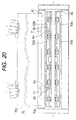
- Figs. 19 and 20 there is shown a typical printing plate-mounting apparatus 60.
- Fig. 20 is a view of the printing plate-mounting apparatus 60 when it is viewed from the direction of the arrow mark X shown in Fig. 19; and, Fig. 19 is a section view taken along the line Y-Y shown in Fig. 20.
- the plate cylinder 61 of the printing machine is structured such that a portion of a cylinder is cut away along the axial direction of the cylinder and, in a substantially flat surface (which is hereinafter referred to as a flat surface portion 61a) which is the cut face of the cutaway portion of the cylinder), there is formed a groove portion 65. And, within the groove portion 65a, there are disposed a plate front end clamp mechanism 62 for holding the front end or leading end of a printing plate 70, and a plate rear end clamp mechanism 63 for holding the rear end or trailing end of the printing plate 70.
- the clamp mechanisms 62 and 63 respectively include lower teeth 62b and 63b the upper surfaces of which are substantially flush with the flat surface portions 61a), and upper teeth 62a and 63a which are rotatably supported by their respective lower teeth and are capable of holding the plate front end or rear end between the upper surfaces of their respective lower teeth and themselves. Further, there is disposed a position adjusting mechanism (not shown) which is capable of adjusting the positions of the plate front end clamp mechanism 62 and plate rear end clamp mechanism 63 in the back-and-forth direction, in the right-and-left direction and in the oblique direction on the bottom surface of the groove portion 65.
- top portions 61c are formed between the upper surfaces of the lower teeth of the clamp mechanisms, instead of the flat surface portions, and the curved portion of the plate cylinder.
- the portions of the plate cylinder 61 where the two flat surface portions 61a and curved surface portion 61b cross each other, are each rounded to thereby provide a curved surface having a radius of 5 - 30 mm. It should be noted here that, in the present specification, such curved surface portions are also referred to as top portions.
- two positioning pins 64 are respectively provided on and projected from the upper surface of the lower tooth 62b of the plate front end clamp mechanism; specifically, at two positions of the lower tooth 62b upper surface which are spaced from each other in the axial direction of the plate cylinder 61.
- the front end portion 70a of the printing plate 70 which is shown by a two-dot chained line in Fig. 20; specifically, at the positions of the front end portion 70a that correspond to the positioning pins 64, there are also formed two notches 71 respectively.
- a plate which, in the present specification, is referred to as a flexible plate comprising a support member formed of material which is inexpensive and easy to handle (for example, plastic film, paper) other than metal, and a photosensitive layer disposed on such support member.
- a plate since such plate is high in flexibility, there arise several problems when it is mounted on the plate cylinder.
- the flexible printing plate 70 is mounted onto the plate cylinder 61 using the printing plate-mounting apparatus shown in Fig. 19 & 20.
- an operator pushes the plate front end 70a of the printing plate between the upper tooth 62a and lower tooth 62b of the plate front end clamp mechanism to thereby bring the plate front end 70a into contact with two positioning pins 64, there is a fear that the plate front end 70a can be deformed and can be fixed in such deformed state.
- the distance between the two positioning pins 64 in the plate cylinder 61 is fairly wide; and, therefore, when mounting the printing plate 70 onto the plate cylinder 61, in case where the operator overpushes the printing plate 70 even slightly, the printing plate 70 can be deformed in such a manner that the plate front end 70a is projected in the pushing direction from between the two positioning pins 64.
- the printing plate 70 cannot be positioned accurately.
- the mountability of the flexible plate onto the plate cylinder is poor and thus it is difficult to always mount the flexible plate onto the plate cylinder in a constant state. Therefore, there are necessary a plurality of plate cylinders and thus, in case where the flexible plate is used in a multicolor printing (for example, four-color printing) which requires strict matching between the plate cylinders, mismatching can occur.
- a multicolor printing for example, four-color printing
- the flexible printing plate 70 does not easily stick to the outer peripheral surface of the plate cylinder 61 but the flexible printing plate 70 tends to float up from the outer peripheral surface of the plate cylinder 61.
- the plate rear end of the printing plate is pushed into between the upper and lower teeth of the plate rear end clamp mechanism, the upper tooth is rotated to thereby fix the plate rear end, and, using a tension apply mechanism (not shown), the plate rear end clamp mechanism is moved in a direction where a tensile force is applied to the printing plate, thereby bringing the printing plate into close contact with the peripheral surface of the plate cylinder, which completes the mounting of the printing plate onto the plate cylinder.
- the tension apply mechanism for contacting the flexible printing plate with the peripheral surface of the plate cylinder closely is designed in combination with a printing plate having a support member formed of metal such as aluminum; and, therefore, in the case of the flexible printing plate, it is stretched more than necessary.
- the tension apply mechanism is designed such that it can apply a lower tensile force according to the flexible printing plate
- the tensile force applied is too weak to closely contact the printing plate with the plate cylinder.
- the printing plate can be mounted onto the plate cylinder in such a manner that the printing plate is prevented from floating up from the plate cylinder, in the case of such weak tensile force, the printing plate deviates in position due to a frictional force which is produced between a rubber cylinder and itself in printing.
- CTP Computer-to-plate
- DDPP Digital Direct Printing Plate
- This technology is advantageous over a conventional plate making method (which provides close-contact exposure with a lith film superimposed on top of a printing plate) in that it can provide better image position accuracy with respect to a flexible printing plate and better matching accuracy in a multicolor printing.
- the present invention aims at eliminating the above-mentioned drawbacks.
- an object of the invention is to provide a flexible plate-mounting member which is capable of mounting a flexible plate onto a plate cylinder positively and easily.
- Another object of the invention to provide flexible printing plate-mounting method and apparatus which is capable of mounting a digitally-made flexible printing plate easily without deforming the same, allows the flexible printing plate to be applied to a conventional printing machine with slight improvements, and allows the flexible printing plate to provide dimensional stability equivalent to that of a metal support member printing plate as well as matching accuracy in a multicolor printing.
- the present invention relates to the following items (1-1) to (1-3).
- the present invention relates to the following items (2-1) to (2-13).
- the flexible plate there can be used a support member which is formed of a plastic film or paper other than metal, and a support member which is a combination of such plastic film and paper support members.
- a support member comprising a plastic film which is formed of polyester, polyethylene terephthalate, polyethylene naphthalate, or polycarbonate; and, a support member comprising a composite sheet which can be produced in such a manner that a plastic sheet formed of polyethylene or polypropylene is laminated on paper.
- the thickness of the support member is set in the range of 75 - 500 ⁇ m, the optimum value of the support member thickness varies according to the kinds of the support members used and printing conditions. Generally, most preferably, the thickness of the support member may be set in the range of 100 - 400 ⁇ m.
- the positioning pin disposed in the plate front end clamp mechanism includes a pin which is provided on and projected from the upper surface of the lower tooth of the plate front end clamp mechanism toward the upper tooth thereof, a pin which is provided on and projected from the lower surface of the upper tooth of the plate front end clamp mechanism toward the lower tooth thereof, and a pin which is provided on and projected from the plate cylinder and is arranged in the vicinity of the plate front end clamp mechanism.
- the material of the base of the plate-mounting member may be higher in rigidity than the flexible plate; for example, metal can be used.
- the fixing pin may be a pin which is formed integral with the base, or a pin which is produced separately and mounted onto the base afterward.
- the front end of the flexible plate can be protected by the plate-mounting member to thereby eliminate the possibility that the plate front end can be projected from between the two positioning pins. Therefore, the mountability of the flexible plate onto the plate cylinder can be enhanced remarkably. This not only can reduce the burden of the operator but also can prevent the above-mentioned mismatching to thereby allow the flexible plate to be used in a multicolor printing as well.
- the plate in case where the plurality of fixing pins are disposed on the base of the plate-mounting member along the width direction of the plate and the distance between the fixing pins is equal to or less than 400 mm, the plate can be prevented from being deformed in such a manner that the plate front end is projected from between the two positioning pins. More preferably, in case where the distance between the fixing pins is equal to or less than 270 mm, the plate can be prevented against deformation more positively.
- the distance between the fixing pins may not be constant, provided it exists in the above-mentioned range.
- the durability of the plate-mounting member can be enhanced.
- a plate-mounting member 30 which provides embodiment 1-1 according to the invention, and a polyester-made printing plate 80 used as a flexible plate onto which the plate-mounting member 30 is to be mounted.
- the plate front end 80a of the printing plate 80 there are formed two notches 81 each having a substantially U-shaped peripheral edge. Also, in the plate front end 80a, there are opened up a plurality of (in this embodiment, 7) fixing holes 82 which are spaced from one another by a given distance W1 in the width direction of the printing plate 80 (the direction along the axial direction of the plate cylinder; in Fig. 21, in the right and left direction). The fixing holes 82 can be formed at the same time when the notches 81 are formed.
- the plate-mounting member 30 is made of steel, stainless steel, other alloy steel, or brass.
- the plate-mounting member 30 includes a band-shaped (a rectangular-shaped) base 31 having a length equal to or greater than the width of the printing plate 80.
- a band-shaped (a rectangular-shaped) base 31 having a length equal to or greater than the width of the printing plate 80.
- on the base 31 there are projectingly provided a plurality of (in this embodiment, 7) fixing pins 32 which are spaced from one another by a given distance in the longitudinal direction of the base 31.
- the plurality of fixing pins 32 are disposed on a straight line extending along the width direction of the printing plate 80, that is, along the longitudinal direction of the plate-mounting member 30.
- the size of the fixing pin 32 is not limited but, for example, the fixing pin 32 can be set such that it has a diameter of 6mm and a height of 4mm or so.
- the transverse-direction width of the base 31 is also not limited but the width may only be set such that the base 31 can be prevented from touching the top portions of the plate cylinder when it is mounted onto the plate cylinder.
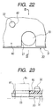
- Fig. 22 shows an enlarged view of the neighboring portion of each notch 81 of the printing plate 80 shown in Fig. 21 when the plate-mounting member 30 is mounted onto the plate front end 80a of the printing plate 80.
- the plate-mounting member 30 can be fixed to the printing plate 80.
- the plate-mounting member 30 and printing plate 80 are set such that a portion of the peripheral edge of the circular-shaped insertion hole 33 of the plate-mounting member 30 can be matched to the curved portion of the substantially U-shaped peripheral edge of the notch 81 of the printing plate 80.
- the plate front end 80a of the printing plate 80 is fixed to the plate-mounting member 30.
- Fig. 23 is a section view taken along the line III-III shown in Fig. 22. As shown by a two-dot chained line in Fig. 23, when the positioning pins 64 of the plate cylinder 61 are inserted into the insertion holes of the plate-mounting member 30, the inner peripheral surface of the notches 81 of the printing plate 80 are contacted with the positioning pins 64 together with the inner peripheral surfaces of the insertion holes 33 of the plate-mounting member 30.
- the plate front end 80a of the printing plate 80 can be protected by the plate-mounting member 30 as well as the printing plate 80 can be prevented from being deformed in such a manner that the plate front end 80a thereof is projected from between the two positioning pins 64. Therefore, not only the mountability of the flexible printing plate 80 onto the plate cylinder can be enhanced remarkably to thereby reduce the burden of the operator, but also the above-mentioned mismatching can be prevented to thereby allow the flexible printing plate 80 to be used in a multicolor printing as well.
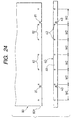
- Fig. 24 shows a plate-mounting member 40, which provides embodiment 1-2 according to the invention, and a printing plate 80.
- the plate-mounting member 40 includes a base 41 having a length equal to or greater than the width of the printing plate 80.
- the portions of the base 41 that respectively correspond to the two positioning pins 64 of the plate cylinder 61 shown in Fig. 20 there are formed two notches 43 each having a substantially U-shaped peripheral edge.
- a plurality of (in this embodiment, 7) fixing pins 42 in such a manner that they are spaced from one another by a given distance W2 (in this embodiment, 120mm) in the longitudinal direction of the base 41.
- Fig. 25 shows an enlarged view of the neighboring portion of each notch 81 of the printing plate 80 when the plate-mounting member 40 is mounted onto the plate front end 80a of the printing plate 80 shown in Fig. 24.
- the plate-mounting member 40 can be fixed to the printing plate 80.
- the plate-mounting member 40 and printing plate 80 are set such that the peripheral edges of the notches 43 of the plate-mounting member 40 can be matched to the peripheral edges of the notches 81 of the printing plate 80.
- the plate front end 80a of the flexible printing plate 80 can be protected by the plate-mounting member 40 but also the printing plate 80 can be prevented from being deformed in such a manner that the plate front end 80a thereof is projected from between the two positioning pins 64.
- the plate-mounting member 40 when the plate front end 80a of the printing plate 80 is fixed to the plate front end clamp mechanism after the plate-mounting member 40 is fixed to the plate front end 80a, the plate-mounting member 40 can be inserted into between the upper and lower teeth of the plate front end clamp mechanism, which makes it possible to further simplify the positioning operation of the plate front end 80a.
- Fig. 26 shows a plate-mounting member 50, which provides embodiment 1-3 according to the invention, and a printing plate 80.
- the plate-mounting member 50 includes a base 51 having a length equal to or greater than the width of the printing plate 80.
- a base 51 having a length equal to or greater than the width of the printing plate 80.
- each of the deformation preventive notches 54 is formed in a trapezoidal shape when it is viewed from above.
- the deformation preventive notches 54 are appropriately deformed in shape so as to be able to prevent the whole of the plate-mounting member 50 from being deformed. That is, the deformation of the whole of the plate-mounting member 50 can be absorbed by the deformation of the deformation preventive notches 54. Therefore, the durability of the plate-mounting member 50 can be enhanced.
- the plate-mounting member according to the first aspect of the invention not only the mountability of the flexible plate onto the plate cylinder can be enhanced remarkably to thereby reduce the burden of the operator, but also the above-mentioned mismatching can be prevented to thereby allow the flexible plate to be used in a multicolor printing as well.
- the maximum printing length in the plate cylinder rotation direction during the printing plate-mounting operation means the maximum length that can be printed on paper; and, in the specification and instruction manual of a printing machine, as such maximum printing length, there is set forth a concrete numeric value.
- this length can be regarded as the length of the area of the plate cylinder on the diameter circumference thereof that extends from the neighboring portion of the top portion of the plate front end to the neighboring portion of the top portion of the plate rear end.
- the pressure member there can be employed a roller-shaped pressure member which can be driven by a driving member so as to be contacted with or separated from the plate cylinder. Also, there may also be used a flat-surface pressure member such as a pad-shaped, brush-shaped, or flat-surface-shaped pressure member, which can be driven by a driving member so as to be contacted with or separated from the plate cylinder.
- the positioning pin there can be employed a pin which is provided on and projected from the upper surface of the lower tooth of the plate front end clamp mechanism toward the upper tooth of the plate front end clamp mechanism, a pin which is provided on and projected from the lower surface of the upper surface toward the lower tooth, or a pin which is provided integrally with the plate cylinder.
- the plate rear end fixing mechanism there can be used a plate rear end clamp mechanism which includes an upper tooth and a lower tooth. Also, there can also be employed a plate rear end hold mechanism using a plate-spring-shaped member, or means for attaching the plate rear end to the plate cylinder surface or a plate rear end clamp member using a double adhesive tape or spray glue.
- the flexible printing plate is contacted with three or more positioning pins and is thereby positioned, the distance between the positioning pins in the plate cylinder is narrow, which can eliminate the possibility that the printing plate can be deformed in such a manner that the plate front end can be projected from between the positioning pins. Also, when winding the printing plate onto the plate cylinder, the pressure member presses the printing plate against the entire outer peripheral surface of the plate cylinder including the top portions thereof to thereby bring the printing plate into close contact with the plate cylinder outer peripheral surface.
- the packing sheet which is capable of preventing the printing plate from deviating in position after it is wound around and fixed to the plate cylinder, supports the wound printing plate strongly, normally, in case where the tensile force of the printing plate is zero or small, the printing plate can be prevented from deviating in position due to a frictional force produced between the printing plate and rubber cylinder during printing.
- the dimensional stability of the printing plate in the printing plate-mounting operation as well as in the printing operation can be enhanced remarkably, which makes it possible to obtain multicolor printing matching accuracy equivalent to that of a metal support member printing plate. Further, the mountability of the flexible printing plate onto the plate cylinder can be enhanced greatly, so that the burden of the operator can be relieved.
- the stretching of the printing plate in the maximum printing length in the plate cylinder rotation direction in the flexible printing plate-mounting operation can be controlled down to 100 ⁇ m or less.
- the first reason for this is that, as described above, when winding the printing plate onto the plate cylinder by rotating the plate cylinder while pulling the plate rear end of the printing plate strongly in order to prevent the printing plate from being floated up from the plate cylinder, the printing plate is easily stretched 100 ⁇ m or more.
- the second reason is that, since the above-mentioned tensile force apply mechanism is designed according to the printing plate using a support member formed of metal such as aluminum, in the case of the flexible printing plate, it is easily stretched 100 ⁇ m or more. Also, in case where the tensile force apply mechanism is so designed according to the flexible printing plate as to apply such a low tensile force that can control the stretching of the printing plate down to 100 ⁇ m or less, the printing plate cannot be closely contacted with the plate cylinder due to shortage of the tensile force.
- the printing plate can be mounted onto the plate cylinder in such a manner that it is prevented from being floated up from the plate cylinder, with such low tensile force, the printing plate can deviate in position due to a frictional force produced between the rubber cylinder and printing plate in the printing operation.
- the flexible printing plate-mounting method according to the invention is a mounting method which does not apply a tensile force to the flexible printing plate positively.
- the plate front end of the printing plate can be protected by the high-rigidity pin contact member including at least three fixing pins and thus the deformation of the plate front end can be prevented. Therefore, without increasing the number of positioning pins used, these structures can be relatively easily applied to an existing printing apparatus and an existing plate making apparatus as well.
- the material of the pin contact member having higher rigidity than the printing plate there can be selected metal.
- the material of the pin contact member is not limited to metal specifically.
- the plate base material supports the printing plate wound on the plate base material with a high frictional force or a high sticky force. This can eliminate the possibility that the printing plate can deviate in position due to a frictional force produced between the rubber cylinder and printing plate during printing after the printing plate is mounted onto the plate cylinder.
- the operator need not execute the rotation and stopping of the plate cylinder as well as the contact and separation of the pressure member with respect to the plate cylinder which have been conventionally necessary when mounting the printing plate onto the plate cylinder. Therefore, not only the burden of the operator can be further relieved but also the flexible printing plate can be mounted onto the plate cylinder quickly.
- JP-A-10-24555 (The term "JP-A" as used herein means an "unexamined published Japanese patent application"), there are disclosed method and apparatus for positioning and fixing the plate front end of a flexible printing plate using three or more reference pins.
- the fixing method and apparatus employ a mechanism in which three or more reference pins are disposed on the upper surface of an upper tooth thereof and the reference pins are fitted into reference holes formed in a printing plate to thereby position and fix the printing plate.
- the reference pins are present between the upper and lower teeth of the plate front end clamp mechanism and are used for contact of the printing plate or pin contact member; and, the plate front end is fixed using the plate front end clamp mechanism.
- the fixing method and apparatus disclosed in the above-cited publication are different from the invention in the structure of the apparatus as well as in the function of the reference pins. Also, in the above-cited publication, there is not disclosed the technological idea of the invention that the flexible printing plate is wound onto the plate cylinder while it is pressed against the entire outer peripheral surface of the plate cylinder using the pressure member.
- a flexible printing plate-mounting apparatus including a plate hold roller which is used to press a flexible printing plate against a plate cylinder.
- the plate front end is contacted with three or more positioning pins, or, the plate front end of the printing plate is fixed to the pin contact member having higher rigidity than the printing plate and the pin contact member is then contacted with the positioning pins.
- a plate rear end clamp mechanism employed in the printing plate-mounting apparatus disclosed in the above-cited registered utility model publication is structured such that it firstly holds the printing plate and, after then, it pulls the printing plate. That is, in this plate rear end clamp mechanism, there is not disclosed the technological idea of the invention that a tensile force is not applied to the printing plate positively.
- Fig. 1 shows embodiment 2-1 of the flexible printing plate-mounting apparatus according to the invention.
- Fig. 1 shows a flexible printing plate-mounting apparatus 10 which is used to mount a flexible (polyester-made) printing plate 70 onto a plate cylinder 11 provided in a printing apparatus for a multicolor printing (four-color printing).
- Fig. 2 is a view of the apparatus 10 taken from the direction of the arrow mark X shown in Fig. 1, showing the plate cylinder 11 according to the present embodiment.
- the flexible printing plate-mounting apparatus 10 comprises a plate cylinder 11 including a plate front end clamp mechanism 12 and a plate rear end clamp mechanism 13; a hold roller 17 and a rubber cylinder 25 which can be respectively contacted with and separated from the outer peripheral surface of the plate cylinder 11; and, guide member 20 which is used to guide the plate front end of the flexible printing plate 70 to the plate front end clamp mechanism 12.
- the plate cylinder 11 can be rotated and stopped by a rotation controller (not shown).
- the controller includes a member of detecting the rotational position of the plate cylinder 11.
- the guide member 20 is structured by disposing a guide roller 23 on the leading end of each of an appropriate number (in the illustrated embodiment, 2) of support members 22 respectively provided on and projected from a plate-shaped member 21.
- an appropriate number in the illustrated embodiment, 2
- the plate-shaped member 21 there is used a cover which covers the side surface of a printing apparatus 500.
- the rubber cylinder 25 is structured such that it can be contacted with and separated from the plate cylinder 11 and thus, when winding the printing plate 70 onto the plate cylinder 11, the printing plate 70 can also be held and pressed by and between the plate cylinder 11 and this rubber cylinder 25.
- a plate base material 27 (a material forming the base part of the plate cylinder 11) at least one surface of which is formed as a roughened surface in such a manner that the roughened surface becomes an outer surface side thereof.
- plastics such as polyethylene terephthalate, polypropylene and polyethylene; or, metal such as aluminum and SUS; or, paper or synthetic paper; or, cloth. That is, any material can be used, provided that it can be well fitted with the plate cylinder 11 of the printing apparatus.
- the hold roller 17, as shown in Fig. 4, is assembled to an appropriate driving member such as a cylinder 18 and is structured such that it can be contacted with or separated from the outer peripheral surface of the plate cylinder 11 by a driving member controller (not shown).
- a driving member controller not shown
- the hold roller 17 may be preferably formed of elastic material such as rubber.
- positioning pins 14 on the upper surface of the lower tooth 12b of the plate front end clamp mechanism 12, there are projectingly provided three or more (in this embodiment, 7) positioning pins 14 in such a manner that they are spaced by a given distance from one another in the axial direction of the plate cylinder 11.
- the seven positioning pins 14 only one positioning pin 14 shown on the right in Fig.
- the other remaining positioning pins 14 are respectively so formed as to have such a section shape that can be obtained by cutting away the two sides of a circle in a direction to cross at right angles to the axial direction of the plate cylinder 11, in order that the widths of these positioning pins 14 in the axial direction of the plate cylinder 11 are narrower than the width of the positioning pin 14 having the above-mentioned circular section shape in the axial direction of the plate cylinder 11.
- the operator When mounting the printing plate 70 onto the thus-structured plate cylinder 11, the operator firstly sets the printing plate 70 on the guide member 20, pushes the printing plate 70 in such a manner that the plate front end 70a is inserted into between the upper tooth 12a and lower tooth 12b of the plate front end clamp mechanism 12, and brings the inner peripheral surfaces of the notches 71 of the plate front end 70a into contact with the positioning pins 14 shown in Fig. 2 to thereby position the plate front end 70a. In this state, the upper tooth 12a is closed to thereby fix the plate front end 70a.
- the plate cylinder 11 is rotated counterclockwise using the rotation controller (not shown) to thereby wind the printing plate 70 onto the plate cylinder 11.
- the controller stops the rotational movement of the plate cylinder 11.
- the hold roller 17 is contacted with the flat surface portion 11a of the plate cylinder 11 and the printing plate 70 is pressed against the outer peripheral surface of the plate cylinder 11. Then, the plate cylinder 11 is rotated again counterclockwise using the rotation controller (not shown). In this manner, the hold roller 17 can be so operated as to press the printing plate 70 against the outer peripheral surface of the plate cylinder 11 before and behind the top portions 11c of the plate cylinder 11. At the then time, the hold roller 17, which is energized by the cylinder 18 toward the outer peripheral surface of the plate cylinder 11, is allowed to advance and retreat according to the shape of the outer peripheral surface of the plate cylinder 11.
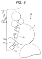
- the plate cylinder 11 is rotated on and, as shown in Fig. 6, at the time when the printing plate 70 is wound on the plate cylinder 11 up to the neighboring portion of the plate rear end clamp mechanism 13, the rotation controller (not shown) stops the rotational movement of the plate cylinder 11.
- the operator curves the neighboring portion of the plate rear end of the printing plate 70 to thereby insert the plate rear end 70b into between the upper tooth 13a and lower tooth 13b of the plate rear end clamp mechanism 13.
- the plate rear end 70b is floated up from the flat surface portion lla of the plate cylinder 11 and the upper surface of the lower tooth 13b.
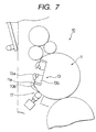
- the plate cylinder 11 is rotated counterclockwise again using the rotation controller (not shown).
- the hold roller 17 can be so operated as to press the printing plate 70 against the outer peripheral surface of the plate cylinder 11 before and behind the top portions 11c of the plate cylinder 11; and, at the same time, as shown in Fig. 8, the plate rear end can be closely contacted with the flat surface portion lla of the plate cylinder 11 and the upper surface of the lower tooth 13b.
- the hold roller 17 is retreated from the printing plate 70 using the rotation controller (not shown), thereby completing the mounting operation of the flexible printing plate onto the plate cylinder 11.
- the plate front end 70a of the flexible printing plate 70 is contacted with the seven positioning pins 14 which are respectively provided on and projected from the lower tooth 12b of the plate front end clamp mechanism, thereby positioning the plate front end 70a. Therefore, the distance between the positioning pins 14 in the plate cylinder is narrow when compared with the distance provided in the conventional printing plate-mounting apparatus; and thus, even in the case of a printing plate of a large size such as a half-kiku size, there is eliminated a fear that the flexible printing plate 70 can be deformed in such a manner that the plate front end 70a is projected from between the positioning pins 14.
- the hold roller 17 presses the flexible printing plate 70 against the top portions (the top portion on the plate front end clamp mechanism 12 side and the top portion on the plate rear end clamp mechanism 13 side) 11c of the outer peripheral surface of the plate cylinder 11 including the portions before and behind the top portions of the outer peripheral surface of the plate cylinder 11, there is no fear that the flexible printing plate 70 wound around the plate cylinder 11 can be floated up from the outer peripheral surface of the plate cylinder 11. Therefore, there is no need for the operator to pull the plate rear end 70b strongly, which can prevent the plate rear end 70b against deformation such as stretch. Also, the burden of the operator in the flexible printing plate-mounting operation can be relieved.
- the operator when fixing the plate rear end 70b to the plate rear end clamp mechanism 13, the operator curves the neighboring portion of the plate rear end 70b of the flexible printing plate 70 to thereby insert the plate rear end 70b into between the upper tooth 13a and lower tooth 13b of the plate rear end clamp mechanism 13. Thanks to this, the plate rear end clamp mechanism 13 need not be structured such that the upper tooth 13a can be opened greatly. That is, the structure of the plate rear end clamp mechanism 13 can be simplified.
- the flexible printing plate-mounting apparatus 10 can be reduced in cost and size.
- the width of only one positioning pin 14 in the axial direction of the plate cylinder 11 is set wider than those of the other remaining positioning pins 14 in the axial direction of the plate cylinder 11. This makes it possible to contact the inner peripheral surfaces of the notches 71 of the flexible printing plate 70 with the positioning pins 14 easily. Also, the flexible printing plate 70 can be positioned accurately by the positioning pin with the plate-cylinder-axial-direction width thereof set wider than those of the other remaining positioning pins 14.
- the plate cylinder 11 can be automatically rotated by the controller, the rotational movement of the plate cylinder 11 can be stopped at a given position, and the hold roller 17 can also be automatically contacted with and separated from the plate cylinder 11 by the controller. This can relieve the burden of the operator further.
- the plate base material 27 at least one surface of which is formed as a roughened surface in such a manner that the roughened surface becomes an outer surface thereof. Due to this, the deformation and positional deviation of the flexible printing plate 70 after the flexible printing plate 70 is contacted with the outer peripheral surface of the plate cylinder 11 can be prevented positively.
- the hold roller 17 when the hold roller 17 is contacted with and separated from the plate cylinder 11, the rotational movement of the plate cylinder 11 is stopped.
- the hold roller 17 may be contacted with and separated from the plate cylinder 11 without stopping the rotational movement of the plate cylinder 11.
- a plate cylinder there is used a conventional plate cylinder 61 which is shown in Figs. 19 and 20. And, on the present plate cylinder 61, there is wound and fixed the plate base material 27 (see Fig. 3), which is used in the previously described embodiment 2-1 and at least one surface of which is formed as a roughened surface, in such a manner that the roughened surface becomes an outer surface thereof.
- the flexible printing plate-mounting apparatus according to embodiment 2-2 has a similar structure to the flexible printing plate-mounting apparatus 10 (see Fig. 1) according to embodiment 2-1, except for the plate cylinder.
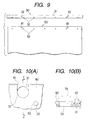
- a flexible printing plate 80 and a pin contact member 30 to be fixed to the plate front end of the flexible printing plate 80 which are both used in the present embodiment.
- the plate front end of the flexible printing plate 80 more specifically, in the portions of the flexible printing plate 80 front end that correspond to two positioning pins 64 shown in Fig. 20, there are formed two notches 81 each having a substantially U-shaped peripheral edge. Also, in the plate front end, there are formed at least three (in this embodiment, 7) fixing holes 82 at appropriate intervals in the width direction (in Fig. 9, in the right and left direction) of the flexible printing plate 80.
- the pin contact member 30 includes a band-shaped base 31 which is formed of high-rigidity material such as metal and has a length equal to or greater than the width of the flexible printing plate 80.
- a band-shaped base 31 which is formed of high-rigidity material such as metal and has a length equal to or greater than the width of the flexible printing plate 80.
- the base 31 specifically, in the portions of the base 31 that correspond to the two positioning pins 64 shown in Fig. 20, there are formed two circular-shaped insertion holes 33.
- the base 31 includes at least three (in this embodiment, 7) fixing pins 32 which are provided on and projected from the base 31 at appropriate intervals in the longitudinal direction of the base 31.
- Fig. 10(A) is an enlarged view of the neighboring portion of each notch 81 of the flexible printing plate 80, showing a state thereof when the pin contact member 30 shown in Fig. 9 is fixed to the plate front end of the flexible printing plate 80.
- Fig. 10(B) is a section view taken along the line Y-Y shown in Fig. 10(A). As shown in Fig. 10(A), by inserting the fixing pin 32 of the pin contact member 30 into its associated fixing hole 82 of the flexible printing plate 80, the pin contact member 30 can be fixed to the flexible printing plate 80.
- the pin contact member 30 and flexible printing plate 80 are set such that a portion of the peripheral edge of the circular-shaped insertion hole 33 of the pin contact member 30 coincides with the curved portion of the substantially U-shaped peripheral edge of the notch 81 of the flexible printing plate 80.
- the plate front end of the flexible printing plate 80 may be firstly fixed to the pin contact member 30 and, after then, the plate front end may be fixed to the plate front end clamp mechanism 62; or, with the two positioning pins 64 of the plate front end clamp mechanism 62 inserted into the two insertion holes 33 of the pin contact member 30, the plate front end of the flexible printing plate 80 may be fixed to the pin contact member 30.
- the present plate front end of the flexible printing plate 80 is positioned and fixed by the plate front end clamp mechanism, the present plate front end is protected by the high-rigidity pin contact member 30, thereby preventing the plate front end against deformation. Therefore, with use of the pin contact member 30, not only the deformation of the printing plate 80 can be prevented without increasing the number of the positioning pins used, but also it is possible to use the plate cylinder 61 of the existing printing apparatus. In case where the present embodiment is enforced using an existing facility, the facility cost of the present embodiment can be reduced to a great extent.
- embodiment 2-3 of the flexible printing plate-mounting apparatus according to the invention with reference to Figs. 11 and 12.
- the pin contact member 30 used in the previously described embodiment 2-2 is changed but the remaining portions of embodiment 2-3 are similar in structure to embodiment 2-2.
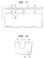
- Fig. 11 shows parts which are used in the present embodiment; that is, a flexible printing plate 80 and a pin contact member 40 to be fixed to the plate front end of the flexible printing plate 80.
- the pin contact member 40 includes a band-shaped base 41 which is formed of high-rigidity material such as metal and has a length equal to or greater than the width of the flexible printing plate 80.
- a band-shaped base 41 which is formed of high-rigidity material such as metal and has a length equal to or greater than the width of the flexible printing plate 80.
- the base 41 specifically, in the portions of the base 41 that correspond to the two positioning pins 64 shown in Fig. 20, there are formed two circular-shaped insertion holes 43.
- the base 41 includes at least three (in this embodiment, 7) fixing pins 42 which are provided on and projected from the base 31 at appropriate intervals in the longitudinal direction of the base 41.
- Fig. 12 is an enlarged view of the neighboring portion of each notch 81 of the flexible printing plate 80, showing a state thereof when the pin contact member 40 is fixed to the plate front end of the flexible printing plate 80.
- the pin contact member 40 by inserting the fixing pin 42 of the pin contact member 40 into its associated fixing hole 82 of the flexible printing plate 80, the pin contact member 40 can be fixed to the flexible printing plate 80.
- the pin contact member 40 and flexible printing plate 80 are set such that a portion of the peripheral edge of the circular-shaped insertion hole 43 of the pin contact member 40 coincides with the curved portion of the substantially U-shaped peripheral edge of the notch 81 of the flexible printing plate 80.
- the pin contact member 40 after the pin contact member 40 is fixed to the plate front end of the flexible printing plate 80, when fixing the present plate front end to the plate front end clamp mechanism, the pin contact member 40 can be inserted into between the upper and lower teeth of the plate front end clamp mechanism to thereby position both of the pin contact member 40 and the plate front end of the flexible printing plate 80. This makes it possible to simplify the plate front end positioning and fixing operation further.
- Fig. 13 shows embodiment 2-4 of the flexible printing plate-mounting apparatus according to the invention.
- the upper tooth 93a of a plate rear end clamp mechanism 93 provided in a plate cylinder 91 can be pulled apart greatly from the upper face of the lower tooth 93b of the plate rear end clamp mechanism 93: that is, the upper tooth 93a can be held in such a manner that it does not cover the upper surface of the lower tooth 93b.
- the upper tooth 93a can be rotated until an angle formed between the lower surface of the upper tooth 93a and the upper surface of the lower surface 93b becomes equal to or greater than an angle where the plate rear end and the clamp surface of the upper tooth 93a are not contacted with each other in a state shown in Fig. 13.
- a plate base material at least one surface of which is formed as a sticky surface in such a manner that the sticky surface becomes an outer surface thereof.
- the sticky surface can be formed, for example, by spraying a spray adhesive onto a sheet-shaped base body, by bonding two-side adhesive tape to the sheet-shaped base body, or by applying sticky material to the base body.
- the plate front end is fixed by a plate front end clamp mechanism 92 and the flexible printing plate 80 is wound around the outer peripheral surface of the plate cylinder 91.
- the upper tooth 93a of the plate rear end clamp mechanism 93 is opened wide to thereby set the upper tooth 93a in a state in which it does not cover the upper surface of the lower tooth 93b.
- a hold roller 17 is contacted with the curved surface portion of the plate cylinder 91 to thereby press the flexible printing plate 70 against the outer peripheral surface of the plate cylinder 91 and, in this state, the plate cylinder 91 is rotated counterclockwise.
- the flexible printing plate 70 can be pressed against the outer peripheral surface of the plate cylinder 91 before and behind the top portions 91c of the plate cylinder 91 and, at the same time, the plate rear end 70b of the flexible printing plate 70 can be closely contacted with the flat surface portion 91a of the plate cylinder 91 and the upper surface of the lower tooth 93b.
- the flexible printing plate-mounting operation can be simplified further and the-thus simplified operation is suitable for automation as well.
- Fig. 14 shows embodiment 2-5 of the flexible printing plate-mounting apparatus according to the invention.
- the pressure member which is used to press a flexible printing plate 70 against the outer peripheral surface of the plate cylinder 91 at least before and behind the top portions of a plate cylinder 101 there is employed a flat surface pressure member.
- the flat surface pressure member is structured such that a brush 117, the leading end portions of which are substantially the same in height so as to form a single flat surface, can be driven by an air cylinder 18 to thereby contact the brush 117 with the plate cylinder 101 and separate the brush 117 from the plate cylinder 101.
- the brush 117 there can be employed a brush formed of chemical synthetic fiber such as nylon, polypropylene, vinyl chloride, PBT and aramide; a brush formed of plant fiber (palm); or, a brush formed of animal fiber (pig fur, horsehair, sheep fur).
- the operation to wind the flexible printing plate 70 onto the plate cylinder 101 is carried out in a similar manner to embodiment 2-1.
- the flexible printing plate 70 can be pressed against the outer peripheral surface of the plate cylinder 101 over a wide range by the flat surface pressure member, in a process for winding the flexible printing plate 70, the accuracy of the timing for stopping the rotation of the plate cylinder 101 may be set low.
- the flexible printing plate 70 can be pressed against the outer peripheral surface of the plate cylinder 101 over a wide range by the flat surface pressure member, the floating of the flexible printing plate 70 from the outer peripheral surface of the plate cylinder 101 can be prevented positively and easily. For example, while rotating and stopping the plate cylinder 101 by hand, the flexible printing plate 70 can be mounted onto the plate cylinder 101.
- the brush is structured such that the leading end portions thereof can be so arranged to form a flat surface.
- the leading end portions of the brush may also be so arranged as to form a plurality of flat surfaces, provided that the brush can press the flexible printing plate 70 against the outer peripheral surface of the plate cylinder 101; for example, the leading end portions of the brush may be arranged such that the section of the brush leading end face is formed as a V shape.
- the flat surface pressure member is structured by using the brush.
- the brush instead of the brush, there can be used a pad which is formed of sponge (urethane sponge, cellulose sponge) or felt. And, it is also possible to use a pad in which core material such as sponge, felt or rubber is covered with molten (cloth).
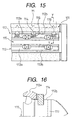
- Fig. 15 is a partially enlarged view of a plate cylinder 111 according to the present embodiment.
- a plate front end clamp mechanism 112 Within a groove portion 115 formed in the plate cylinder 111, there are disposed a plate front end clamp mechanism 112 and a plate rear end clamp mechanism 113.
- notches each having a rectangular shape when it is viewed from above, in such a manner that they are spaced from each other at a given interval in the axial direction of the plate cylinder 111; and, in each notch, there is disposed a pin block 119 which is formed integral with the plate cylinder 111. And, a positioning pin 114 is provided on and projected from the pin block 119.
- Fig. 16 which is a section view taken along the line Y-Y shown in Fig. 15, one side surface of the pin block 119 is closely contacted with the side surface of the groove portion 115.
- the positioning pin 114 is formed integral with the plate cylinder 111 through the pin block 119. Due to this, the plate front end portion can be positioned with more accuracy.
- FIG. 17 is a partially enlarged view of a plate cylinder 121 according to embodiment 2-7.
- the clamp mechanisms 122 and 123 respectively include plate-shaped upper teeth 122a and 123a.
- the upper teeth 122a and 123a are respectively fixed within the groove portion 125.
- Fig. 18 is a section view taken along the line Y-Y shown in Fig. 17.
- a shaft-shaped cam member 130 the diameter of which is reduced at the portions that correspond to the positioning pins 124 hanging from the upper tooth 122a.
- a plate spring 131 By rotating the cam member 130, the upper tooth 122a and plate spring 131 can opened and closed with respect to each other, which makes it possible to hold the plate front end of the flexible printing plate 70. That is, in the present embodiment, the plate spring 131 substantially functions as a lower tooth for holding the plate front end between the upper tooth 122a and itself.
- the positioning pins 124 are disposed on the upper tooth 122a in such a manner that they extend toward the lower tooth 122b; and thus, the upper tooth 122a is not movable. Therefore, a hold roller can be made to approach very closely to the upper tooth 122a, so that the flexible printing plate 70 can be closely contacted with the plate cylinder 121 more positively.
- the dimensional stability of the flexible printing plate in the flexible printing plate-mounting operation and printing operation can be enhanced remarkably, thereby being able to obtain multicolor printing matching accuracy equivalent to that of a metal support member printing plate.
- the mountability of the flexible printing plate onto a plate cylinder can also be enhanced greatly, which makes it possible to reduce the burden of an operator. Further, since the invention can also be enforced simply by improving an existing printing machine to a slight degree, the facility cost of the invention can be saved.
Landscapes
- Engineering & Computer Science (AREA)
- Mechanical Engineering (AREA)
- Supply, Installation And Extraction Of Printed Sheets Or Plates (AREA)
Abstract
Description
Claims (16)
- A plate-mounting member to be attached to a plate front end of a flexible plate in order to mount said flexible plate having a plurality of fixing holes onto a plate cylinder including a plate front end clamp mechanism having upper and lower teeth and at least two positioning pins disposed between upper and lower teeth, said plate-mounting member comprising a base and a plurality of fixing pins disposed on said base to be respectively inserted into said plurality of fixing holes formed in said plate front end, wherein said base is to be attached to said positioning pins disposed in said plate front end clamp mechanism to thereby position said plate front end.
- The plate-mounting member according to Claim 1, wherein said plurality of fixing pins are disposed on said base along the width direction of said plate and the distance between adjacent fixing pins is not more than 400 mm.
- The plate-mounting member according to Claim 1 or 2, wherein deformation preventive notches are formed in the portions of said base that are to be held by said upper and lower teeth.
- A flexible printing plate-mounting method for mounting a flexible printing plate having three or more notches formed in a plate front end thereof onto a plate cylinder, comprising the steps of:providing a flexible printing plate-mounting apparatus comprising:a plate front end positioning and fixing mechanism comprising: a plate front end clamp mechanism having upper teeth and lower teeth for fixing the plate front end of said printing plate to said plate cylinder; and at least three positioning pins respectively disposed in said plate front end clamp mechanism in such a manner that they are respectively opposed to said notches of said printing plate;a printing plate pressure mechanism for pressing said printing plate against said plate cylinder;a plate rear end fixing mechanism for fixing the plate rear end of said printing plate to said plate cylinder; anda packing sheet which is wound and fixed to said plate cylinder and has a function of preventing positional deviation of said printing plate; positioning and fixing said plate front end to saidplate cylinder by inserting the plate front end of said printing plate into between said upper and lower teeth of said plate front end clamp mechanism to contact the inner peripheral surfaces of said notches of said plate front end with said at least three positioning pins;winding said printing plate onto said plate cylinder by rotating said plate cylinder with said plate rear end set free, while said printing plate pressure mechanism presses said printing plate against the entire outer peripheral surface of said plate cylinder including top portions thereof using a pressure member; andpressing and fixing said plate rear end of said printing plate in a radial direction of said plate cylinder using said plate rear end fixing mechanism after completion of said winding;whereby stretching of said flexible printing plate in its maximum printing length in the rotational direction of said plate cylinder during said printing plate-mounting operation is suppressed to 100 µm or less.
- A flexible printing plate-mounting method for mounting a flexible printing plate having at least three fixing holes formed in a plate front end thereof onto a plate cylinder, comprising the steps of:providing a flexible printing plate-mounting apparatus comprising:a plate front end positioning and fixing mechanism comprising: a plate front end clamp mechanism having upper teeth and lower teeth for fixing the plate front end of said printing plate to said plate cylinder; positioning pins disposed in said plate front end clamp mechanism; and a pin contact member which has higher rigidity than said printing plate, is to be attached to said positioning pin and has at least three fixing pins for fixing said printing plate;a printing plate pressure mechanism for pressing said printing plate against said plate cylinder;a plate rear end fixing mechanism for fixing the plate rear end of said printing plate to said plate cylinder; anda packing sheet which is wound and fixed to said plate cylinder and has a function of preventing positional deviation of said printing plate;positioning and fixing said plate front end to said plate cylinder by allowing said fixing holes of said printing plate to be inserted with said fixing pins of said pin contact member between said upper and lower teeth of said plate front end clamp mechanism;winding said printing plate onto said plate cylinder by rotating said plate cylinder with said plate rear end set free, while said printing plate pressure mechanism presses said printing plate against the entire outer peripheral surface of said plate cylinder including top portions thereof using a pressure member; andpressing and fixing said plate rear end of said printing plate in a radial direction of said plate cylinder using said plate rear end fixing mechanism after completion of said winding;whereby stretching of said flexible printing plate in its maximum printing length in the rotational direction of said plate cylinder during said printing plate-mounting operation is suppressed to 100 µm or less.
- A flexible printing plate-mounting method for mounting a flexible printing plate having at least three fixing holes formed in a plate front end thereof onto a plate cylinder, comprising the steps of:providing a flexible printing plate-mounting apparatus comprising:a plate front end positioning and fixing mechanism comprising: a plate front end clamp mechanism having upper teeth and lower teeth for fixing the plate front end of said printing plate to said plate cylinder; and a positioning pin disposed in said plate front end clamp mechanism;a printing plate pressure mechanism for pressing said printing plate against said plate cylinder;a plate rear end fixing mechanism for fixing the plate rear end of said printing plate to said plate cylinder;a packing sheet which is wound and fixed to said plate cylinder and has a function of preventing positional deviation of said printing plate; anda pin contact member which has higher rigidity than said printing plate and includes at least three fixing pins for fixing said printing plate;fixing said printing plate on said pin contact member by allowing said fixing holes of said printing plate to be inserted into said fixing pins of said pin contact member, respectively;fixing and positioning said printing plate onto said plate cylinder by fixing a leading end of said pin contact member to said positioning pin between said upper and lower teeth of said plate front end clamp mechanism;winding said printing plate onto said plate cylinder by rotating said plate cylinder with said plate rear end set free, while said printing plate pressure mechanism presses said printing plate against the entire outer peripheral surface of said plate cylinder including top portions thereof using a pressure member; andpressing and fixing said plate rear end of said printing plate in a radial direction of said plate cylinder using said plate rear end fixing mechanism after completion of said winding;whereby stretching of said flexible printing plate in its maximum printing length in the rotational direction of said plate cylinder during said printing plate-mounting operation is suppressed to 100 µm or less.
- The flexible printing plate-mounting method according to any one of Claims 4 to 6, wherein said packing sheet has at least one roughened surface, and said packing sheet is wound and fixed onto said plate cylinder in such a manner that said roughened surface side becomes an outer surface side.
- The flexible printing plate-mounting method according to any one of Claims 4 to 6, wherein said packing sheet has at least one sticky surface, and said packing sheet is wound and fixed onto said plate cylinder in such a manner that said sticky surface side becomes an outer surface side.
- The flexible printing plate-mounting method according to any one of Claims 4 to 8, wherein said flexible printing plate-mounting apparatus further comprises a guide member for holding said printing plate, wherein said guide member holds said printing plate, before and during mounting said printing plate onto said plate cylinder, in such a manner that the plate rear end thereof is set free.
- A flexible printing plate-mounting apparatus for mounting a flexible printing plate having three or more notches formed in a plate front end thereof onto a plate cylinder, said flexible printing plate-mounting apparatus comprising:a plate front end positioning and fixing mechanism comprising: a plate front end clamp mechanism having upper teeth and lower teeth for fixing the plate front end of said printing plate to said plate cylinder; and at least three positioning pins respectively disposed in said plate front end clamp mechanism in such a manner that they are respectively opposed to said notches of said printing plate;a printing plate pressure mechanism for pressing said printing plate against said plate cylinder;a plate rear end fixing mechanism for fixing the plate rear end of said printing plate to said plate cylinder; anda packing sheet which is wound and fixed to said plate cylinder and has a function of preventing positional deviation of said printing plate.
- A flexible printing plate-mounting apparatus for mounting a flexible printing plate onto a plate cylinder, said flexible printing plate-mounting apparatus comprising:a plate front end positioning and fixing mechanism comprising: a plate front end clamp mechanism having upper teeth and lower teeth for fixing the plate front end of said printing plate to said plate cylinder; positioning pins disposed in said plate front end clamp mechanism; and a pin contact member which has higher rigidity than said printing plate, is to be attached to said positioning pin and has at least three fixing pins for fixing said printing plate;a printing plate pressure mechanism for pressing said printing plate against said plate cylinder;a plate rear end fixing mechanism for fixing the plate rear end of said printing plate to said plate cylinder; anda packing sheet which is wound and fixed to said plate cylinder and has a function of preventing positional deviation of said printing plate.
- A flexible printing plate-mounting apparatus for mounting a flexible printing plate onto a plate cylinder, said flexible printing plate-mounting apparatus comprising:a plate front end positioning and fixing mechanism comprising: a plate front end clamp mechanism having upper teeth and lower teeth for fixing the plate front end of said printing plate to said plate cylinder; and a positioning pin disposed in said plate front end clamp mechanism;a printing plate pressure mechanism for pressing said printing plate against said plate cylinder;a plate rear end fixing mechanism for fixing the plate rear end of said printing plate to said plate cylinder;a packing sheet which is wound and fixed to said plate cylinder and has a function of preventing positional deviation of said printing plate; anda pin contact member which has higher rigidity than said printing plate and includes at least three fixing pins for fixing said printing plate.
- The flexible printing plate-mounting apparatus according to any one of Claims 10 to 12, wherein said packing sheet has at least one roughened surface, and said packing sheet is wound and fixed onto said plate cylinder in such a manner that said roughened surface side becomes an outer surface side.
- The flexible printing plate-mounting apparatus according to any one of Claims 10 to 12, wherein said packing sheet has at least one sticky surface, and said packing sheet is wound and fixed onto said plate cylinder in such a manner that said sticky surface side becomes an outer surface side.
- The flexible printing plate-mounting apparatus according to any one of Claims 10 to 14, further comprising a guide member for holding said printing plate, before and during mounting said printing plate onto said plate cylinder, in such a manner that the plate rear end thereof is set free.
- The flexible printing plate-mounting apparatus according to any one of Claims 10 to 15, further comprising:a rotating member for rotating said plate cylinder when mounting said printing plate onto said plate cylinder;a detector for detecting the rotational position of said plate cylinder;a rotation controller for controlling the rotation and stopping of said plate cylinder rotating member at given positions in accordance with signals from said rotational position detector;a driving member for driving said pressure member so as to be into contact with or separated from said plate cylinder; anda controller for controlling said driving member at given positions in accordance with signals from said rotational position detector.
Applications Claiming Priority (4)
| Application Number | Priority Date | Filing Date | Title |
|---|---|---|---|
| JP2000043031 | 2000-02-21 | ||
| JP2000043031A JP4351781B2 (en) | 2000-02-21 | 2000-02-21 | Plate mounting material |
| JP2000070598A JP2001260320A (en) | 2000-03-14 | 2000-03-14 | Method and device for fitting flexible printing plate |
| JP2000070598 | 2000-03-14 |
Publications (3)
| Publication Number | Publication Date |
|---|---|
| EP1127687A2 true EP1127687A2 (en) | 2001-08-29 |
| EP1127687A3 EP1127687A3 (en) | 2003-04-09 |
| EP1127687B1 EP1127687B1 (en) | 2011-04-13 |
Family
ID=26585753
Family Applications (1)
| Application Number | Title | Priority Date | Filing Date |
|---|---|---|---|
| EP01103606A Expired - Lifetime EP1127687B1 (en) | 2000-02-21 | 2001-02-21 | Plate-mounting member, and method and apparatus for mounting flexible printing plate |
Country Status (3)
| Country | Link |
|---|---|
| US (1) | US6736065B2 (en) |
| EP (1) | EP1127687B1 (en) |
| DE (1) | DE60144403D1 (en) |
Cited By (3)
| Publication number | Priority date | Publication date | Assignee | Title |
|---|---|---|---|---|
| EP1310364A1 (en) * | 2001-11-07 | 2003-05-14 | Fuji Photo Film Co., Ltd. | Method and apparatus for attaching a flexible printing plate |
| FR2841175A1 (en) * | 2002-06-25 | 2003-12-26 | Michel Piqueux | Embossing adaptor for offset printing press has blanket cylinder and counter-pressure cylinders carrying sleeves retained by wedges with aligning pins |
| WO2008064960A1 (en) * | 2006-12-01 | 2008-06-05 | Koenig & Bauer Aktiengesellschaft | Method for operating a printing unit having at least one press unit, and a press unit for carrying out the method |
Families Citing this family (5)
| Publication number | Priority date | Publication date | Assignee | Title |
|---|---|---|---|---|
| JP4210139B2 (en) * | 2002-03-23 | 2009-01-14 | エルジー ディスプレイ カンパニー リミテッド | Liquid crystal dropping device capable of adjusting the dropping amount of liquid crystal depending on the height of the spacer and dropping method thereof |
| US7802935B2 (en) * | 2005-05-25 | 2010-09-28 | Agfa Graphics Nv | Printing table for a flatbed printing machine |
| EP2253471A1 (en) * | 2009-05-18 | 2010-11-24 | Müller Martini Holding AG | Pressurised cylinder with rubber blanket for a roller offset printing press |
| US8397636B2 (en) * | 2010-09-22 | 2013-03-19 | E I Du Pont De Nemours And Company | Method and apparatus for tensioning a printing form |
| AU2012277305B2 (en) * | 2011-06-30 | 2014-11-06 | Koenig & Bauer Ag | Method of mounting and adjusting a printing plate on a plate cylinder of a multicolour offset printing press |
Family Cites Families (8)
| Publication number | Priority date | Publication date | Assignee | Title |
|---|---|---|---|---|
| US1788662A (en) * | 1928-12-20 | 1931-01-13 | Gestetner Ltd | Duplicating with the aid of stencils |
| US2553856A (en) * | 1946-03-01 | 1951-05-22 | Addressograph Multigraph | Clamp for master sheets of printing machines |
| GB840745A (en) | 1956-02-24 | 1960-07-13 | Wilhelm Ritzerfeld | Improvements in or relating to pliable printing master sheets |
| US3406629A (en) * | 1967-01-31 | 1968-10-22 | Mosstype Corp | Printing plate carrier transfer mounting system |
| US3537395A (en) * | 1968-03-18 | 1970-11-03 | Grace W R & Co | Saddles for flexible thin printing plates |
| EP0660776B1 (en) | 1992-09-18 | 1996-12-27 | KOENIG & BAUER-ALBERT AKTIENGESELLSCHAFT | Printing plates feeding process |
| US5562039A (en) * | 1995-09-05 | 1996-10-08 | E. I. Du Pont De Nemours And Company | Method for mounting a flexible printing plate onto a printing cylinder |
| EP1312474A1 (en) * | 1998-04-13 | 2003-05-21 | Fuji Photo Film Co., Ltd. | Printing method and printing apparatus, and packing sheet material for printing plate material |
-
2001
- 2001-02-21 US US09/788,619 patent/US6736065B2/en not_active Expired - Fee Related
- 2001-02-21 DE DE60144403T patent/DE60144403D1/en not_active Expired - Lifetime
- 2001-02-21 EP EP01103606A patent/EP1127687B1/en not_active Expired - Lifetime
Cited By (6)
| Publication number | Priority date | Publication date | Assignee | Title |
|---|---|---|---|---|
| EP1310364A1 (en) * | 2001-11-07 | 2003-05-14 | Fuji Photo Film Co., Ltd. | Method and apparatus for attaching a flexible printing plate |
| US6776096B2 (en) | 2001-11-07 | 2004-08-17 | Fuji Photo Film Co., Ltd. | Method for attaching a flexible printing plate to a plate cylinder |
| FR2841175A1 (en) * | 2002-06-25 | 2003-12-26 | Michel Piqueux | Embossing adaptor for offset printing press has blanket cylinder and counter-pressure cylinders carrying sleeves retained by wedges with aligning pins |
| WO2008064960A1 (en) * | 2006-12-01 | 2008-06-05 | Koenig & Bauer Aktiengesellschaft | Method for operating a printing unit having at least one press unit, and a press unit for carrying out the method |
| EP2116377A1 (en) * | 2006-12-01 | 2009-11-11 | Koenig & Bauer AG | Method for operating a nine cylinders satellite printing unit |
| US7963226B2 (en) | 2006-12-01 | 2011-06-21 | Koenig & Bauer Aktiengesellschaft | Method for operating a printing unit having at least one press unit, and a press unit for carrying out the method |
Also Published As
| Publication number | Publication date |
|---|---|
| EP1127687B1 (en) | 2011-04-13 |
| US6736065B2 (en) | 2004-05-18 |
| DE60144403D1 (en) | 2011-05-26 |
| US20010023648A1 (en) | 2001-09-27 |
| EP1127687A3 (en) | 2003-04-09 |
Similar Documents
| Publication | Publication Date | Title |
|---|---|---|
| US8087440B2 (en) | Embossing device | |
| EP1127687B1 (en) | Plate-mounting member, and method and apparatus for mounting flexible printing plate | |
| JPH08501036A (en) | How to supply plate | |
| EP0919371B1 (en) | Coating device, printing device, imaging device, printing system, and printing method | |
| EP1957270B1 (en) | Method for mounting a plate to an adhesive member | |
| US20080028966A1 (en) | Method for Feeding a Printing Forme to a Forme Cylinder of a Printing Press, Method for Producing A Printing Forme and Device For Laterally Aligning And Guiding A Dressing To Be Fed To A Printing Press Cylinder | |
| JP2728435B2 (en) | Stencil printing machine | |
| US5243379A (en) | Exposure drum mask | |
| EP0741022B1 (en) | Clamp assembly for lithographic plates | |
| EP0722900A2 (en) | Print sheet leading end mounting device having means for lifting released leading end | |
| JP4037013B2 (en) | Plate material installation method | |
| JPH07251560A (en) | Rotary stencil printer | |
| JP2003154628A (en) | Method and apparatus for sticking photosensitive resin plate onto printing sleeve | |
| US6467411B1 (en) | Printing plate mounting apparatus having guide member for bending plate towards cylinder | |
| EP0679523B1 (en) | Method for making prints by means of a thermal printer | |
| US6088883A (en) | Clip connected unit | |
| JP3272660B2 (en) | Surface material mounting device for cylinder of printing press | |
| JPS5822172A (en) | Plate fitting register for lithographic printer | |
| JP3626548B2 (en) | Printing device | |
| JPH06278262A (en) | Magnetic cylinder blanket | |
| JP2000263907A (en) | Plate cylinder type printing device with print image left / right position adjustment mechanism | |
| JPH09141821A (en) | Printing device | |
| GB2114935A (en) | Printing | |
| EP1084854A1 (en) | Stencil making and attaching method of printing device | |
| JP2001018363A (en) | Method for attaching flexible printing plate and block copy sheet for printing plate |
Legal Events
| Date | Code | Title | Description |
|---|---|---|---|
| PUAI | Public reference made under article 153(3) epc to a published international application that has entered the european phase |
Free format text: ORIGINAL CODE: 0009012 |
|
| AK | Designated contracting states |
Kind code of ref document: A2 Designated state(s): AT BE CH CY DE DK ES FI FR GB GR IE IT LI LU MC NL PT SE TR |
|
| AX | Request for extension of the european patent |
Free format text: AL;LT;LV;MK;RO;SI |
|
| PUAL | Search report despatched |
Free format text: ORIGINAL CODE: 0009013 |
|
| AK | Designated contracting states |
Kind code of ref document: A3 Designated state(s): AT BE CH CY DE DK ES FI FR GB GR IE IT LI LU MC NL PT SE TR Designated state(s): AT BE CH CY DE DK ES FI FR GB GR IE IT LI LU MC NL PT SE TR |
|
| AX | Request for extension of the european patent |
Extension state: AL LT LV MK RO SI |
|
| 17P | Request for examination filed |
Effective date: 20030604 |
|
| AKX | Designation fees paid |
Designated state(s): DE GB |
|
| RAP1 | Party data changed (applicant data changed or rights of an application transferred) |
Owner name: FUJIFILM CORPORATION |
|
| 17Q | First examination report despatched |
Effective date: 20071015 |
|
| GRAP | Despatch of communication of intention to grant a patent |
Free format text: ORIGINAL CODE: EPIDOSNIGR1 |
|
| GRAS | Grant fee paid |
Free format text: ORIGINAL CODE: EPIDOSNIGR3 |
|
| GRAA | (expected) grant |
Free format text: ORIGINAL CODE: 0009210 |
|
| AK | Designated contracting states |
Kind code of ref document: B1 Designated state(s): DE GB |
|
| REG | Reference to a national code |
Ref country code: GB Ref legal event code: FG4D |
|
| REF | Corresponds to: |
Ref document number: 60144403 Country of ref document: DE Date of ref document: 20110526 Kind code of ref document: P |
|
| REG | Reference to a national code |
Ref country code: DE Ref legal event code: R096 Ref document number: 60144403 Country of ref document: DE Effective date: 20110526 |
|
| PLBE | No opposition filed within time limit |
Free format text: ORIGINAL CODE: 0009261 |
|
| STAA | Information on the status of an ep patent application or granted ep patent |
Free format text: STATUS: NO OPPOSITION FILED WITHIN TIME LIMIT |
|
| 26N | No opposition filed |
Effective date: 20120116 |
|
| REG | Reference to a national code |
Ref country code: DE Ref legal event code: R097 Ref document number: 60144403 Country of ref document: DE Effective date: 20120116 |
|
| GBPC | Gb: european patent ceased through non-payment of renewal fee |
Effective date: 20120221 |
|
| REG | Reference to a national code |
Ref country code: DE Ref legal event code: R119 Ref document number: 60144403 Country of ref document: DE Effective date: 20120901 |
|
| PG25 | Lapsed in a contracting state [announced via postgrant information from national office to epo] |
Ref country code: GB Free format text: LAPSE BECAUSE OF NON-PAYMENT OF DUE FEES Effective date: 20120221 |
|
| PG25 | Lapsed in a contracting state [announced via postgrant information from national office to epo] |
Ref country code: DE Free format text: LAPSE BECAUSE OF NON-PAYMENT OF DUE FEES Effective date: 20120901 |