EP1127601A2 - Rectification column for the separation of a multi-substance mixture - Google Patents
Rectification column for the separation of a multi-substance mixture Download PDFInfo
- Publication number
- EP1127601A2 EP1127601A2 EP01103686A EP01103686A EP1127601A2 EP 1127601 A2 EP1127601 A2 EP 1127601A2 EP 01103686 A EP01103686 A EP 01103686A EP 01103686 A EP01103686 A EP 01103686A EP 1127601 A2 EP1127601 A2 EP 1127601A2
- Authority
- EP
- European Patent Office
- Prior art keywords
- cross
- segments
- segment
- sectional area
- wall column
- Prior art date
- Legal status (The legal status is an assumption and is not a legal conclusion. Google has not performed a legal analysis and makes no representation as to the accuracy of the status listed.)
- Granted
Links
Images


Classifications
-
- B—PERFORMING OPERATIONS; TRANSPORTING
- B01—PHYSICAL OR CHEMICAL PROCESSES OR APPARATUS IN GENERAL
- B01D—SEPARATION
- B01D3/00—Distillation or related exchange processes in which liquids are contacted with gaseous media, e.g. stripping
- B01D3/14—Fractional distillation or use of a fractionation or rectification column
- B01D3/141—Fractional distillation or use of a fractionation or rectification column where at least one distillation column contains at least one dividing wall
-
- B—PERFORMING OPERATIONS; TRANSPORTING
- B01—PHYSICAL OR CHEMICAL PROCESSES OR APPARATUS IN GENERAL
- B01D—SEPARATION
- B01D3/00—Distillation or related exchange processes in which liquids are contacted with gaseous media, e.g. stripping
- B01D3/14—Fractional distillation or use of a fractionation or rectification column
-
- Y—GENERAL TAGGING OF NEW TECHNOLOGICAL DEVELOPMENTS; GENERAL TAGGING OF CROSS-SECTIONAL TECHNOLOGIES SPANNING OVER SEVERAL SECTIONS OF THE IPC; TECHNICAL SUBJECTS COVERED BY FORMER USPC CROSS-REFERENCE ART COLLECTIONS [XRACs] AND DIGESTS
- Y10—TECHNICAL SUBJECTS COVERED BY FORMER USPC
- Y10S—TECHNICAL SUBJECTS COVERED BY FORMER USPC CROSS-REFERENCE ART COLLECTIONS [XRACs] AND DIGESTS
- Y10S159/00—Concentrating evaporators
- Y10S159/906—Wick
-
- Y—GENERAL TAGGING OF NEW TECHNOLOGICAL DEVELOPMENTS; GENERAL TAGGING OF CROSS-SECTIONAL TECHNOLOGIES SPANNING OVER SEVERAL SECTIONS OF THE IPC; TECHNICAL SUBJECTS COVERED BY FORMER USPC CROSS-REFERENCE ART COLLECTIONS [XRACs] AND DIGESTS
- Y10—TECHNICAL SUBJECTS COVERED BY FORMER USPC
- Y10S—TECHNICAL SUBJECTS COVERED BY FORMER USPC CROSS-REFERENCE ART COLLECTIONS [XRACs] AND DIGESTS
- Y10S203/00—Distillation: processes, separatory
- Y10S203/20—Power plant
Definitions
- the invention relates to a dividing wall column for separating a A multicomponent mixture and a process for the pure distillation of p-methoxycinnamic acid ethyl hexyl ester.
- multicomponent mixtures must have column arrangements that consist of there are at least two separate columns.
- the reinforcing part of the inlet part is the upper region of the inlet part, which is located above the inlet point, and the stripping part of the inlet part is the lower part of the inlet part, which is located below the inlet point.
- the removal part is divided into an upper part, which is located above the side trigger point and a lower part, which is located below the side trigger point.
- a dividing wall column is in principle an apparatus simplification of thermally coupled distillation columns, although the latter have higher investment costs. Partition wall columns and thermally coupled columns offer advantages over the arrangement of conventional distillation columns in terms of both energy consumption and investment costs and are therefore preferably used industrially. Partition wall columns can be configured both as packing columns or packing columns containing ordered packings or as tray columns.
- Dividing wall columns are usually designed in such a way that the dividing wall runs vertically and the cross-sectional areas of the removal part and the inflow part are of the same size. Further information on dividing wall columns is given, for example, in EP-A-0 122 367, in EP-B-0 126 288 and in EP-B-0 133 510.
- the object of the present invention is a dividing wall column to be provided, in particular at low operating pressures of approximately 0.5 to 20 mbar works cheaper and with better separation performance than previously known Partition columns. Particular care should be taken to ensure that the Segments of this dividing wall column in the distillation process optimal be used.
- Segment f) is between segments b) and c) and accordingly Segment g) between segments d) and e).
- segments b) and d) the same number and the same types of separating internals on.
- segments c) and e) contain the same number and the same types of separating internals.
- the upper column area and the lower column area preferably contains separating internals
- the intermediate area usually has no internally separable internals.
- the advantage of the dividing wall column according to the invention is that, in particular at low operating pressures of approximately 0.5 to 20 mbar, the corresponding distillative separation can be carried out more cheaply and with a better separation performance than in comparison with a dividing wall column according to the prior art.
- the F factor is a measure of the load caused by the gas flow in the column - a measure of the momentum of this gas (F factor: gas velocity in the dimension m / s multiplied by the root of the gas density in the dimension kg / m 3 ).
- F factor gas velocity in the dimension m / s multiplied by the root of the gas density in the dimension kg / m 3 .
- the dividing wall column according to the invention can thus be optimally adapted to the respective separation task - no segments are installed which have an unnecessarily large dimension for the corresponding separation problem, as a result of which the expenditure on equipment is reduced and the corresponding separation process can be designed more cost-effectively.
- the segments can also be equipped with different separating internals and distribution devices for liquid.
- special distributors can be provided, the design and dimensioning of which takes place within the framework of the definition of the cross-sectional relationships of the segments.
- the selection of the corresponding cross-sectional ratios is usually carried out in such a way that favorable conditions for the liquid distribution result in particular at low operating pressures of approximately 0.5 to approximately 20 mbar when low liquid sprinkling densities are present.
- the separating internals in the segments are usually selected so that there are minimal investment costs.
- the preferred ratio of the cross-sectional areas depends on the distribution ratio of the liquid at the upper end of the partition and on the operating pressure P.
- the operating pressure is to be understood as the top pressure of the dividing wall column.
- the cross-sectional area A b of segment b) is at least 40%, preferably at least 60%, smaller than the cross-sectional area A d of segment d).
- the cross-sectional area A c of segment c) is usually larger by at least 40%, preferably at least 60%, than the cross-sectional area A e of segment e).
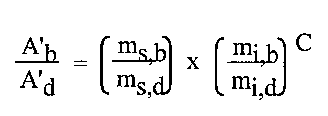
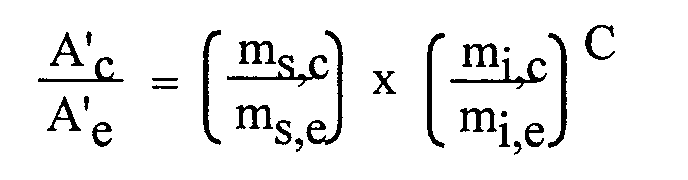
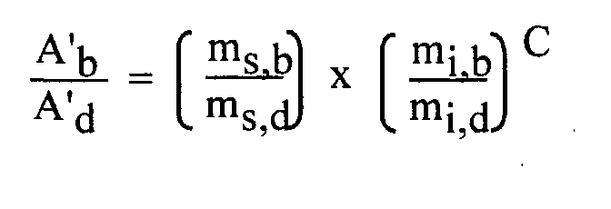
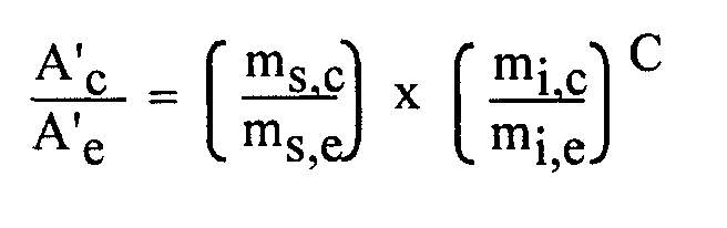
- the operating pressure P is between 0.0005 and 10 bar and the calculated ratios of the cross-sectional areas A ' b / A' d and A ' c / A' e result from the following relationships:
- a ' b , A' d , A ' c , A' e mean the cross-sectional areas of the segments b, d, c, e provided for the calculation; m s, b , m s, d , m s, c , m s, e , the gas volume flows flowing through the segments b, d, c, e, measured in m 3 / h, m i, b , m i, d , m i, c , m i, e the liquid volume flows flowing through the segments b, d, c, e, measured in m 3 / h, and the exponent C results as an operating pressure-dependent variable from the empirically determined function shown in FIG.
- the calculated ratios A ' b / A' d and A ' c / A' e differ from the corresponding, actually existing ratios A b / A d and A c / A e by a maximum of 30%, preferably by a maximum of 20% .
- the desired area ratios can also be realized for ordered packs, since the production of the ordered packing elements at the manufacturing companies is now usually carried out under computer control.
- the division of the separation stages should be preferably be made so that the overall height of the segment b) with the of segment e) and the height of segment c) with that of segment d) matches as closely as possible.
- the division of the separation stages should be preferably be made so that the overall height of the segment b) with the of segment e) and the height of segment c) with that of segment d) matches as closely as possible.
- the operating pressure of the dividing wall column is frequently from 0.0005 to 0.02 bar and liquid distributors are used in which the liquid distribution is based on the accumulation principle and the downstream fine liquid distribution is based on the capillary principle.
- the number of draining points is preferably approximately 200 / m 2 to 1000 / m 2 .
- Preferred types are channel trough distributors. Both channel trough distributors in which the capillary liquid distribution is circular and those in which the capillary liquid distribution is linear are suitable.
- the different types however, have in common that they can give small amounts of liquid in high distribution quality on large cross-sectional areas. Together with the optimized cross-sectional ratios of the segments, this results in favorable designs for columns that work at low pressures of 0.5 to 10 mbar.
- Organized packings are often used as separating internals Cross channel structure used.
- the top pack is below the Liquid distributors mostly aligned so that the individual layers are parallel are aligned with the partition.
- the dividing wall is preferred attached to the column wall by welding.
- detachable connections, or the partition as in the EP-A-0 804 951 describes to loosely mount between the packs.
- the Piece of the partition which is located between the segments f) and g), is usually attached by welding.
- the partition between the segments f) and g) usually arranged obliquely, these usually against the horizontal an angle of 25 to 75 °, preferably from 55 to 65 °, forms. With this arrangement, turbulence in the gas flow, which can largely impair the separation performance.
- the liquid is fed to the inlet part with the help of a pump promoted or over a static inlet height of at least approx. lm abandoned quantity-controlled.
- the control is usually set so that the the amount of liquid added to the feed section is not less than 30% of the "Normal values" (the normal value is the quantity that is to be considered in the corresponding continuous process on average over time per unit of time a certain point occurs) can decrease.
- both internal and external collection spaces for the liquid are suitable for removing and dividing the liquid at the upper end of the dividing wall and at the side removal point, which take over the function of a pump template.
- tray columns it is particularly expedient for this to enlarge the downcomer to about 2 to 3 times the usual height and to store the corresponding amount of liquid in the downcomer.
- the liquid is first collected in collectors and from there it is led into an internal or external collecting space.
- swing funnels offer an inexpensive alternative.
- the liquid can also advantageously be accumulated in a chimney plate.
- the feed mixture introduced contains 70 to 95%, preferably 75 to 90%, of ethyl hexyl p-methoxycinnamate as the medium-boiling product of value.
- this mixture usually also contains 1 to 5% low-boiling by-products and 5 to 25% higher-boiling by-products.
- the number of plates in the correspondingly used dividing wall column is usually about 35 theoretical plates and the ratios of the cross-sectional areas A b / A d are generally between 1: 1.6 and 1: 2.4, preferably 1: 1.8 to 1: 2, 2, and A c / A e between 1: 1.6 and 1: 2.4, preferably between 1: 1.8 to 1: 2.2.
- the dividing wall column is then operated at a top pressure of 1 to 10 mbar, preferably at 4 to 6 mbar.
- the present invention also relates to a method for distillation Pure recovery of p-methoxycinnamic acid ethyl hexyl ester using a dividing wall column described above.
- the method according to the invention is characterized in that the introduced feed mixture (11, 12, 13) as medium-boiling product of value (12) 70 to 95%, preferably 75 to 90%, p-methoxycinnamic acid ethyl hexyl ester contains.
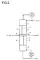
- FIG. 2 shows the separation of a multicomponent mixture Feed mixture 11, 12, 13 in a dividing wall column according to the invention in a low boiler 11, in a medium-boiling valuable product 12 and in one Heavy boiler 13.
- the partition 7, 8 is in its upper and lower part 7 arranged vertically and obliquely in its central part 8.
- the upper Column area 1 is located above the dividing wall 7, 8, and the lower one Column area 6 is arranged below the partition 7, 8.
- the inflow flows into segment f) 9 and the side deduction point is with segment g) 10 connected.
- the dividing wall column used as the test column had a diameter of 0.2 meters, was fitted over a total height of 7 meters with wire mesh packs which had a specific surface area of 500 m 3 / m 2 , and contained a theoretical number of dividing plates of a total of 41 steps.
- the partition was welded between 8th and 30th stages, counted from below.
- the inlet point and the removal point for the liquid side draw were arranged at the same height.
- the liquid was divided into segments b) 2 and d) 3 of the column in a ratio of 1: 3.
- the area ratio of segments b) 2 and d) 3 of the column was 1: 2
- the area ratio of segments c) 4 and e ) 5 of the column was 2: 1.
- the central region 8 of the dividing wall 7, 8 was arranged obliquely and had an angle of 60 ° to the horizontal.
- the head pressure was 5 mbar.
- the feed mixture 11, 12, 13 was fed into the column in liquid form in a flow rate of 8.5 kg / h and at a temperature of approximately 170 °.
- the latter contained 85% p-methoxycinnamic acid ethyl hexyl ester, 5% low-boiling by-products and 10% higher-boiling by-products.
Landscapes
- Chemical & Material Sciences (AREA)
- Chemical Kinetics & Catalysis (AREA)
- Organic Low-Molecular-Weight Compounds And Preparation Thereof (AREA)
- Vaporization, Distillation, Condensation, Sublimation, And Cold Traps (AREA)
- Treatment Of Liquids With Adsorbents In General (AREA)
Abstract
Die Erfindung betrifft eine Trennwandkolonne, die folgende Segmente aufweist:
Wesentlich ist, daß die Trennwand (7) zwischen den Segmenten b) (2) und d) (3)
sowie zwischen den Segmenten c) (4) und e) (5) senkrecht angeordnet ist, die
Segmente b) (2), d) (3), c) (4) und e) (5) trennwirksame Einbauten aufweisen und
die Querschnittsfläche Ab des Segmentes b) (2) um mindestens 10% kleiner ist als
die Querschittsfläche Ad von Segment d) (3), sowie die Querschnittsfläche Ac des
Segmentes c) (4) um mindestens 10% größer ist als die von Segment e) (5).

Description
Die Erfindung betrifft eine Trennwandkolonne zur Auftrennung eines Vielstoffgemischs und ein Verfahren zur destillativen Reingewinnung von p-Methoxyzimtsäureethylhexylester.The invention relates to a dividing wall column for separating a A multicomponent mixture and a process for the pure distillation of p-methoxycinnamic acid ethyl hexyl ester.
Bei der Auftrennung von Zulaufgemischen in mehr als zwei hochreine Fraktionen - zum Beispiel in Leichtsieder, Mittelsieder und Hochsieder ― müssen normalerweise mehrere Destillationskolonnen eingesetzt werden. Um den apparativen Aufwand zu begrenzen, setzt man bei der Auftrennung von Vielstoffgemischen, die aus mehr als zwei Komponenten bestehen, Kolonnen ein, die sich für die Seitenentnahme flüssiger und gasförmiger Medien eignen. Die Anwendungsmöglichkeit von Destillationskolonnen mit Seitenabzügen ist jedoch dadurch stark eingeschränkt, daß die an den Seitenabzugsstellen entnommenen Produkte normalerweise nicht völlig rein sind. Bei Seitenentnahmen im Verstärkungsteil einer Destillationsvorrichtung, die üblicherweise in flüssiger Form erfolgen, enthalten die Seitenprodukte noch Anteile an leichtsiedenden Komponenten, die im Normalfall über Kopf abgetrennt werden. Entsprechendes gilt für Seitenentnahmen im Abtriebsteil, die meist dampfförmig erfolgen und bei denen entnommene Seitenprodukte noch Anteile des Hochsieders aufweisen. Bei der Verwendung solcher konventioneller Seitenabzugskolonnen werden praktisch immer verunreinigte Seitenprodukte erhalten - die Verwendung von Seitenabzugskolonnen ist daher zur Gewinnung von Reinstoffen ungeeignet. When separating feed mixtures into more than two high-purity fractions - for example in low boilers, medium boilers and high boilers - must normally several distillation columns are used. To the To limit equipment expenditure, one sets in the separation of Multi-substance mixtures consisting of more than two components, columns one, which are suitable for the side removal of liquid and gaseous media. The However, distillation columns with side draws can be used severely limited by the fact that the removed at the side trigger points Products are usually not completely pure. With page withdrawals in Strengthening part of a distillation device, usually in liquid Form take place, the side products still contain parts of low-boiling Components that are normally removed overhead. Corresponding applies to side withdrawals in the stripping section, which are mostly vaporized and at from which side products still have portions of the high boiler. At the use of such conventional side draw columns become practical always get contaminated side products - the use of Side draw columns are therefore unsuitable for the extraction of pure substances.
Insbesondere zur Isolierung von mittelsiedenden Reinstoffen aus Vielstoffgemischen müssen somit in der Regel Kolonnenanordnungen, die aus mindestens zwei separaten Kolonnen bestehen, eingesetzt werden.Especially for the isolation of medium-boiling pure substances As a rule, multicomponent mixtures must have column arrangements that consist of there are at least two separate columns.
Eine vorteilhafte Alternative sind sogenannte Trennwandkolonnen. Der Einsatz von Trennwandkolonnen ermöglicht es, Seitenprodukte, also mittelsiedende Komponenten, ebenfalls in reiner Form aus Vielstoffgemischen zu isolieren. Bei Trennwandkolonnen ist im mittleren Bereich eine Trennwand angebracht. Diese erstreckt sich oberhalb und unterhalb der Zulaufstelle. Auf der anderen Seite, die sich gegenüber der Zulaufstelle befindet, ist mindestens eine Seitenabzugsstelle angeordnet, die sich auf gleicher Höhe, unterhalb oder oberhalb der Zulaufstelle befindet. Zwischen Seitenabzugsstelle und Zulaufstelle befindet sich die Trennwand. Diese ist senkrecht angeordnet. In dem Kolonnenbereich, der durch die Trennwand geteilt wird, ist eine Quervermischung von Flüssigkeits- und Brüdenströmen nicht möglich. Dadurch verringert sich bei der Auftrennung von Vielstoffgemischen die Zahl der insgesamt benötigten Destillationskolonnen. Eine Trennwandkolonne weist in der Regel folgende Segmente auf:
- Einen oberen Kolonnenbereich, der sich oberhalb der Trennwand befindet,
- einen Zulaufteil, der sich auf der Seite der Zulaufstelle befindet und seitlich durch die Trennwand abgegrenzt wird,
- einen Entnahmenteil, der sich auf der Seite der Seitenabzugsstelle befindet und seitlich durch die Trennwand abgegrenzt wird und
- einen unteren Kolonnenbereich, der sich unterhalb der Trennwand befindet
- An upper column area, which is located above the partition,
- an inlet part, which is located on the side of the inlet point and is delimited laterally by the partition,
- a removal part, which is located on the side of the side trigger and is laterally delimited by the partition and
- a lower column area, which is located below the partition
Der Verstärkungsteil des Zulaufteils ist der obere Bereich des Zulaufteils, welcher sich oberhalb der Zulaufstelle befindet, und der Abtriebsteil des Zulaufteils ist der untere Teil des Zulaufteils, der sich unterhalb der Zulaufstelle befindet. Der Entnahmeteil ist in einen oberen Teil, der sich oberhalb der Seitenabzugsstelle befindet und einen unteren Teil, der sich unterhalb der Seitenabzugsstelle befindet, unterteilt. Eine Trennwandkolonne ist im Prinzip eine apparative Vereinfachung von thermisch gekoppelten Destillationskolonnen, wobei jedoch letztere höhere Investionskosten aufweisen. Trennwandkolonnen und thermisch gekoppelte Kolonnen bieten gegenüber der Anordnung von konventionellen Destillationskolonnen sowohl hinsichtlich des Energiebedarfs als auch der Investitionskosten Vorteile und werden daher bevorzugt industriell eingesetzt. Trennwandkolonnen können sowohl als Füllkörper oder geordnete Packungen enthaltende Packungskolonnen oder als Bodenkolonnen ausgestaltet sein. Werden Packungskolonnen eingesetzt, so sind geordnete Gewebepackungen mit einer spezifischen Oberfläche von 300 bis 800 m2/m3, bevorzugt von 500 bis 750 m2/m3, besonders geeignet. Üblicherweise sind Trennwandkolonnen so ausgestaltet, daß die Trennwand senkrecht verläuft und die Querschnittsflächen des Entnahmeteils und des Zulaufteils gleich groß sind. Weitere Informationen über Trennwandkolonnen sind beispielsweise in der EP-A-0 122 367, in der EP-B-0 126 288 und in der EP-B-0 133 510 aufgeführt.The reinforcing part of the inlet part is the upper region of the inlet part, which is located above the inlet point, and the stripping part of the inlet part is the lower part of the inlet part, which is located below the inlet point. The removal part is divided into an upper part, which is located above the side trigger point and a lower part, which is located below the side trigger point. A dividing wall column is in principle an apparatus simplification of thermally coupled distillation columns, although the latter have higher investment costs. Partition wall columns and thermally coupled columns offer advantages over the arrangement of conventional distillation columns in terms of both energy consumption and investment costs and are therefore preferably used industrially. Partition wall columns can be configured both as packing columns or packing columns containing ordered packings or as tray columns. If packing columns are used, then ordered tissue packs with a specific surface area of 300 to 800 m 2 / m 3 , preferably of 500 to 750 m 2 / m 3 , are particularly suitable. Dividing wall columns are usually designed in such a way that the dividing wall runs vertically and the cross-sectional areas of the removal part and the inflow part are of the same size. Further information on dividing wall columns is given, for example, in EP-A-0 122 367, in EP-B-0 126 288 and in EP-B-0 133 510.
Die Aufgabe der vorliegenden Erfindung ist, eine Trennwandkolonne bereitzustellen, die insbesondere bei niedrigen Betriebsdrücken von ca. 0,5 bis 20 mbar kostengünstiger und mit besserer Trennleistung arbeitet als bisher bekannte Trennwandkolonnen. Dabei soll insbesondere darauf geachtet werden, daß die Segmente dieser Trennwandkolonne bei dem Destillationsverfahren optimal genutzt werden.The object of the present invention is a dividing wall column to be provided, in particular at low operating pressures of approximately 0.5 to 20 mbar works cheaper and with better separation performance than previously known Partition columns. Particular care should be taken to ensure that the Segments of this dividing wall column in the distillation process optimal be used.
Die Lösung dieser Aufgabe ist dann eine Trennwandkolonne, die im mittleren
Bereich durch eine Trennwand in ein Zulaufteil und einen Entnahmeteil
aufgegliedert ist, aufweisend als Segmente
Segment f) befindet sich zwischen den Segmenten b) und c) und entsprechend Segment g) zwischen den Segmenten d) und e). Meist weisen die Segmente b) und d) die gleiche Anzahl und die gleichen Typen von trennwirksamen Einbauten auf. In der Regel enthalten die Segmente c) und e) die gleiche Anzahl und die gleichen Typen von trennwirksamen Einbauten. Der obere Kolonnenbereich und der untere Kolonnenbereich enthalten bevorzugt trennwirksame Einbauten - der Zwischenbereich weist jedoch meist keine trennwirksamen Einbauten auf.Segment f) is between segments b) and c) and accordingly Segment g) between segments d) and e). Usually the segments b) and d) the same number and the same types of separating internals on. As a rule, segments c) and e) contain the same number and the same types of separating internals. The upper column area and the lower column area preferably contains separating internals However, the intermediate area usually has no internally separable internals.
Der Vorteil der erfindungsgemäßen Trennwandkolonne ist, daß insbesondere bei niedrigen Betriebsdrücken von ca. 0,5 bis 20 mbar die entsprechende destillative Trennung kostengünstiger und mit einer besseren Trennleistung ausführbar ist als vergleichsweise mit einer Trennwandkolonne nach dem Stand der Technik. Diese vorteilhaften Ergebnisse werden insbesondere bei solchen Anwendungsfällen erreicht, bei denen - bedingt durch das aufgegebene Vielstoffgemisch - die Belastung in den Segmenten b) und e) vergleichsweise niedrig und in den Segmenten c) und d) vergleichsweise hoch ist. Somit werden die Segmente entsprechend dem F-Faktor dimensioniert. Der F-Faktor ist ein Maß für die Belastung, die durch den Gasstrom in der Kolonne hervorgerufen wird - ein Maß für den Impuls dieses Gases (F-Faktor: Gasgeschwindigkeit in der Dimension m/s multipliziert mit der Wurzel der Gasdichte in der Dimension kg/m3). Bei einem höheren F-Faktor wird entsprechend in dem betreffenden Segment eine größere Querschnittsfläche bereitgestellt. Dies führt zu einer optimalen Belastung des entsprechenden Segmentes und somit zu einer besseren Trennleistung. Umgekehrt werden Segmente, die weniger stark belastet werden, kleiner dimensioniertsomit wird eine hinreichende Benetzung der enthaltenden trennwirksamen Einbauten mit einem Flüssigkeitsfilm gewährleistet; falls letztere Segmente größer dimensioniert wären, wären entsprechende trennwirksame Einbauten normalerweise nicht vollständig benetzt. Eine vollständige Benetzung der trennwirksamen Einbauten ist jedoch Voraussetzung für eine hohe Trennleistung. Die erfindungsgemäße Trennwandkolonne kann somit an die jeweilige Trennaufgabe optimal angepaßt werden - es werden keine Segmente eingebaut, welche für das entsprechende Trennproblem eine unnötig hohe Dimensionierung aufweisen, wodurch der apparative Aufwand verringert wird, und das entsprechende Trennverfahren kostengünstiger gestaltet werden kann.The advantage of the dividing wall column according to the invention is that, in particular at low operating pressures of approximately 0.5 to 20 mbar, the corresponding distillative separation can be carried out more cheaply and with a better separation performance than in comparison with a dividing wall column according to the prior art. These advantageous results are achieved, in particular, in those applications in which - due to the multicomponent mixture given - the load in the segments b) and e) is comparatively low and in the segments c) and d) is comparatively high. Thus the segments are dimensioned according to the F-factor. The F factor is a measure of the load caused by the gas flow in the column - a measure of the momentum of this gas (F factor: gas velocity in the dimension m / s multiplied by the root of the gas density in the dimension kg / m 3 ). With a higher F-factor, a larger cross-sectional area is accordingly provided in the relevant segment. This leads to an optimal loading of the corresponding segment and thus to a better separation performance. Conversely, segments that are less heavily loaded are dimensioned smaller, thus ensuring adequate wetting of the separating internals containing them with a liquid film; if the latter segments were dimensioned larger, corresponding separating internals would normally not be completely wetted. However, complete wetting of the separating internals is a prerequisite for high separating performance. The dividing wall column according to the invention can thus be optimally adapted to the respective separation task - no segments are installed which have an unnecessarily large dimension for the corresponding separation problem, as a result of which the expenditure on equipment is reduced and the corresponding separation process can be designed more cost-effectively.
Die Segmente können gegebenenfalls auch mit unterschiedlichen trennwirksamen
Einbauten und Verteilungseinrichtungen für Flüssigkeit bestückt sein. Bei
Anwendungen im Vakuumbereich können spezielle Verteiler vorgesehen werden,
deren Auslegung und Dimensionierung im Rahmen der Festlegung der
Querschnittsverhältnisse der Segmente erfolgt. Die Wahl der entsprechenden
Querschnittsverhältnisse wird meist so vorgenommen, daß sich insbesondere bei
niedrigen Betriebsdrücken von etwa 0,5 bis ca. 20 mbar bei Vorliegen von
niedrigen Flüssigkeitsberieselungsdichten günstige Bedingungen für die
Flüssigkeitsverteilung ergeben. Die Trenneinbauten in den Segmenten werden in
der Regel so ausgewählt, daß sich minimale Investitionskosten dafür ergeben. Das
bevorzugte Verhältnis der Querschnittsflächen hängt vom Aufteilungsverhältnis
der Flüssigkeit am oberen Ende der Trennwand und von dem Betriebsdruck P ab.
Unter dem Betriebsdruck soll der Kopfdruck der Trennwandkolonne verstanden
werden.
In der Regel ist die Querschnittsfläche Ab des Segmentes b) um mindestens 40 %,
bevorzugt um mindestens 60 %, kleiner als die Querschnittsfläche Ad von
Segment d). Außerdem ist meist die Querschnittsfläche Ac des Segmentes c) um
mindestens 40 %, bevorzugt um mindestens 60 %, größer als die Querschnittsfläche
Ae von Segment e).If necessary, the segments can also be equipped with different separating internals and distribution devices for liquid. For applications in the vacuum area, special distributors can be provided, the design and dimensioning of which takes place within the framework of the definition of the cross-sectional relationships of the segments. The selection of the corresponding cross-sectional ratios is usually carried out in such a way that favorable conditions for the liquid distribution result in particular at low operating pressures of approximately 0.5 to approximately 20 mbar when low liquid sprinkling densities are present. The separating internals in the segments are usually selected so that there are minimal investment costs. The preferred ratio of the cross-sectional areas depends on the distribution ratio of the liquid at the upper end of the partition and on the operating pressure P. The operating pressure is to be understood as the top pressure of the dividing wall column.
As a rule, the cross-sectional area A b of segment b) is at least 40%, preferably at least 60%, smaller than the cross-sectional area A d of segment d). In addition, the cross-sectional area A c of segment c) is usually larger by at least 40%, preferably at least 60%, than the cross-sectional area A e of segment e).
In einer bevorzugten Ausführungsform der Erfindung beträgt der Betriebsdruck P
zwischen 0,0005 und 10 bar und die berechneten Verhältnisse der Querschnittsflächen
A'b / A'd sowie A'c / A'e ergeben sich aus folgenden Beziehungen:
Dabei bedeuten A'b, A'd, A'c, A'e die zur Berechnung vorgesehenen Querschnittsflächen der Segmente b,d,c,e ; ms,b, ms,d, ms,c, ms,e, die durch die Segmente b,d,c,e strömenden Gasvolumenströme, gemessen in m3/h, mi,b, mi,d, mi,c, mi,e die durch die Segmente b,d,c,e strömenden Flüssigkeitsvolumenströme, gemessen in m3/h und der Exponent C ergibt sich als betriebsdruckabhängige Variable aus der in Figur 3 dargestellten, empirisch ermittelten Funktion. Dabei weichen die berechneten Verhältnisse A'b / A'd sowie A'c / A'e von den entsprechenden, tatsächlich vorliegenden Verhältnissen Ab / Ad sowie Ac / Ae um maximal 30%, bevorzugt um maximal 20%, ab. In der Trennwandkolonne können auch für geordnete Packungen entsprechend gewünschte Flächenverhältnisse realisiert werden, da die Fertigung der geordneten Packungselemente bei den Herstellerfirmen inzwischen üblicherweise computergesteuert erfolgt.A ' b , A' d , A ' c , A' e mean the cross-sectional areas of the segments b, d, c, e provided for the calculation; m s, b , m s, d , m s, c , m s, e , the gas volume flows flowing through the segments b, d, c, e, measured in m 3 / h, m i, b , m i, d , m i, c , m i, e the liquid volume flows flowing through the segments b, d, c, e, measured in m 3 / h, and the exponent C results as an operating pressure-dependent variable from the empirically determined function shown in FIG. The calculated ratios A ' b / A' d and A ' c / A' e differ from the corresponding, actually existing ratios A b / A d and A c / A e by a maximum of 30%, preferably by a maximum of 20% . In the dividing wall column, the desired area ratios can also be realized for ordered packs, since the production of the ordered packing elements at the manufacturing companies is now usually carried out under computer control.
Bei der Auslegung der Trennwandkolonne sollte die Aufteilung der Trennstufen bevorzugt so vorgenommen werden, daß die Bauhöhe des Segments b) mit der des Segments e) und die Bauhöhe des Segmentes c) mit der des Segmentes d) möglichst gut übereinstimmt. Falls sich jedoch entsprechend ungleiche Bauhöhen der Trenneinbauten nicht umgehen lassen, werden in den Segmenten b) und e) oder in den Segmenten c) und d) Teilbereiche nicht mit Trenneinbauten versehen. Durch eine geeignete Wahl von Trenneinbauten verschiedener Trennleistung lassen sich solche Freiräume jedoch in der Praxis meist vermeiden.When designing the dividing wall column, the division of the separation stages should be preferably be made so that the overall height of the segment b) with the of segment e) and the height of segment c) with that of segment d) matches as closely as possible. However, if there are unequal heights of built-in separations cannot be avoided, are in segments b) and e) or in segments c) and d) do not provide partitions. Through a suitable choice of separating components with different separating capacities however, such free spaces can usually be avoided in practice.
Häufig beträgt der Betriebsdruck der Trennwandkolonne 0,0005 bis 0,02 bar und es werden Flüssigkeitsverteiler eingesetzt, bei denen die Flüssigkeitsverteilung nach dem Anstauprinzip und die nachgeschaltete Flüssigkeitsfeinverteilung nach dem Kapillarprinzip erfolgt. Die Zahl der Abtropfstellen beträgt vorzugsweise etwa 200/m2 bis 1000/m2. Bevorzugte Bauarten sind Kanalrinnenverteiler. Es eignen sich sowohl Kanalrinnenverteiler, bei denen die kapillare Flüssigkeitsverteilung kreisförmig, als auch solche, bei denen die kapillare Flüssigkeitsverteilung linear angeordnet ist. Den verschiedenen Bauarten ist jedoch gemeinsam, daß diese kleine Flüssigkeitsmengen in hoher Verteilgüte auf große Querschnittsflächen aufgeben können. Gemeinsam mit den optimierten Querschnittsverhältnissen der Segmente ergeben sich somit günstige Bauformen für Kolonnen, welche bei niedrigen Drücken von 0,5 bis 10 mbar arbeiten.The operating pressure of the dividing wall column is frequently from 0.0005 to 0.02 bar and liquid distributors are used in which the liquid distribution is based on the accumulation principle and the downstream fine liquid distribution is based on the capillary principle. The number of draining points is preferably approximately 200 / m 2 to 1000 / m 2 . Preferred types are channel trough distributors. Both channel trough distributors in which the capillary liquid distribution is circular and those in which the capillary liquid distribution is linear are suitable. The different types, however, have in common that they can give small amounts of liquid in high distribution quality on large cross-sectional areas. Together with the optimized cross-sectional ratios of the segments, this results in favorable designs for columns that work at low pressures of 0.5 to 10 mbar.
Häufig werden als trennwirksame Einbauten geordnete Packungen in Kreuzkanalstruktur eingesetzt. Dabei ist die oberste Packung unterhalb der Flüssigkeitsverteiler meist so ausgerichtet, daß die einzelnen Schichten parallel zur Trennwand ausgerichtet sind.Organized packings are often used as separating internals Cross channel structure used. The top pack is below the Liquid distributors mostly aligned so that the individual layers are parallel are aligned with the partition.
Bei der Konstruktion der Trennwandkolonne wird die Trennwand bevorzugt durch Einschweißen an die Kolonnenwand befestigt. Es ist jedoch auch prinzipiell möglich, dabei lösbare Verbindungen vorzusehen, oder die Trennwand, wie in der EP-A-0 804 951 beschrieben, lose zwischen den Packungen zu montieren. Das Stück der Trennwand, welches sich zwischen den Segmenten f) und g) befindet, wird in der Regel durch Einschweißen befestigt. Dabei ist die Trennwand zwischen den Segmenten f) und g) in der Regel schräg angeordnet, wobei diese meist gegen die Horizontale einen Winkel von 25 bis 75°, bevorzugt von 55 bis 65°, bildet. Bei dieser Anordnung werden Verwirbelungen des Gasstroms, welche die Trennleistung beeinträchtigen können, weitgehend vermieden.In the construction of the dividing wall column, the dividing wall is preferred attached to the column wall by welding. However, it is also fundamental possible to provide detachable connections, or the partition, as in the EP-A-0 804 951 describes to loosely mount between the packs. The Piece of the partition which is located between the segments f) and g), is usually attached by welding. Here is the partition between the segments f) and g) usually arranged obliquely, these usually against the horizontal an angle of 25 to 75 °, preferably from 55 to 65 °, forms. With this arrangement, turbulence in the gas flow, which can largely impair the separation performance.
In der Regel wird die Flüssigkeit auf den Zulaufteil mit Hilfe einer Pumpe gefördert oder über eine statische Zulaufhöhe von mindestens ca. lm mengengeregelt aufgegeben. Die Regelung wird meist so eingestellt, daß die auf den Zulaufteil aufgegebene Flüssigkeitsmenge nicht unter 30% des "Normalwertes" (als Normalwert soll die Menge angesehen werden, die bei dem entsprechenden kontinuierlichen Verfahren im zeitlichen Mittel pro Zeiteinheit an einer bestimmten Stelle anfällt) sinken kann. Meist wird die Aufteilung der aus dem Segment d) im Entnahmeteil ablaufenden Flüssigkeit auf den Seitenabzug und auf das Segment e) im Entnahmeteil durch eine Regelung so eingestellt, daß die auf das Segment e) aufgegebene Flüssigkeitsmenge nicht unter 30% des "Normalwertes" sinken kann.As a rule, the liquid is fed to the inlet part with the help of a pump promoted or over a static inlet height of at least approx. lm abandoned quantity-controlled. The control is usually set so that the the amount of liquid added to the feed section is not less than 30% of the "Normal values" (the normal value is the quantity that is to be considered in the corresponding continuous process on average over time per unit of time a certain point occurs) can decrease. Usually the division of the the segment d) liquid running out in the withdrawal part on the side trigger and adjusted to the segment e) in the removal part by a control so that the amount of liquid added to segment e) is not less than 30% of the "Normal values" can decrease.
Zur Entnahme und Aufteilung der Flüssigkeit am oberen Ende der Trennwand
und an der Seitenentnahmestelle eignen sich sowohl innenliegende, als auch
außerhalb der Kolonne angeordnete Auffangräume für die Flüssigkeit, welche die
Funktion einer Pumpenvorlage übernehmen. Bei Bodenkolonnen ist es besonders
günstig, hierzu den Ablaufschacht auf etwa das 2- bis 3-fache der üblichen Höhe
zu vergrößern und in dem Ablaufschacht die entsprechende Flüssigkeitsmenge zu
speichern. Bei der Verwendung von gepackten Kolonnen wird die Flüssigkeit
zunächst in Sammlern gefaßt und von dort aus in einen innenliegenden oder
außenliegenden Auffangraum geleitet. Allgemein bieten Schwenktrichter eine
kostengünstige Alternative. Im Fall von Bodenkolonnen und bei Vorliegen von
höheren Drücken kann die Flüssigkeit auch vorteilhaft in einem Kaminboden
angestaut werden.
In einer bevorzugten Ausführungsform der Erfindung enthält das eingeführte
Zulaufgemisch als mittelsiedendes Wertprodukt 70 bis 95%, bevorzugt 75 bis
90% p-Methoxyzimtsäureethylhexylester. Both internal and external collection spaces for the liquid are suitable for removing and dividing the liquid at the upper end of the dividing wall and at the side removal point, which take over the function of a pump template. In the case of tray columns, it is particularly expedient for this to enlarge the downcomer to about 2 to 3 times the usual height and to store the corresponding amount of liquid in the downcomer. When using packed columns, the liquid is first collected in collectors and from there it is led into an internal or external collecting space. In general, swing funnels offer an inexpensive alternative. In the case of plate columns and when there are higher pressures, the liquid can also advantageously be accumulated in a chimney plate.
In a preferred embodiment of the invention, the feed mixture introduced contains 70 to 95%, preferably 75 to 90%, of ethyl hexyl p-methoxycinnamate as the medium-boiling product of value.
Neben p-Methoxyzimtsäureethylhexylester enthält dieses Gemisch außerdem meist noch 1 bis 5% leichtersiedende Nebenprodukte und 5 bis 25% höhersiedende Nebenprodukte. Dann betragen die Trennstufenzahl der entsprechend eingesetzten Trennwandkolonne meist etwa 35 theoretische Trennstufen und die Verhältnisse der Querschnittsflächen Ab / Ad in der Regel zwischen 1 : 1,6 und 1 : 2,4, bevorzugt 1 : 1,8 bis 1 : 2,2, sowie Ac / Ae zwischen 1 : 1,6 und 1 : 2,4, bevorzugt zwischen 1 : 1,8 bis 1 : 2,2. Entsprechend wird dann die Trennwandkolonne bei einem Kopfdruck von 1 bis 10 mbar, bevorzugt bei 4 bis 6 mbar, betrieben.In addition to p-methoxycinnamate, this mixture usually also contains 1 to 5% low-boiling by-products and 5 to 25% higher-boiling by-products. Then the number of plates in the correspondingly used dividing wall column is usually about 35 theoretical plates and the ratios of the cross-sectional areas A b / A d are generally between 1: 1.6 and 1: 2.4, preferably 1: 1.8 to 1: 2, 2, and A c / A e between 1: 1.6 and 1: 2.4, preferably between 1: 1.8 to 1: 2.2. Accordingly, the dividing wall column is then operated at a top pressure of 1 to 10 mbar, preferably at 4 to 6 mbar.
Die vorliegende Erfindung betrifft auch ein Verfahren zur destillativen Reingewinnung von p-Methoxyzimtsäureethylhexylester unter Verwendung einer vorstehend beschriebenen Trennwandkolonne. Das erfindungsgemäße Verfahren ist dadurch gekennzeichnet, daß das eingeführte Zulaufgemisch (11, 12, 13) als mittelsiedendes Wertprodukt (12) 70 bis 95%, bevorzugt 75 bis 90%, p-Methoxyzimtsäureethylhexylester enthält.The present invention also relates to a method for distillation Pure recovery of p-methoxycinnamic acid ethyl hexyl ester using a dividing wall column described above. The method according to the invention is characterized in that the introduced feed mixture (11, 12, 13) as medium-boiling product of value (12) 70 to 95%, preferably 75 to 90%, p-methoxycinnamic acid ethyl hexyl ester contains.
Die anliegende Zeichnung zeigt
- in Fig. 1 ein Schema einer Trennwandkolonne nach dem Stand der Technik,
- in Fig. 2 ein Schema einer erfindungsgemäßen Trennwandkolonne und
- in Fig. 3 die Abhängigkeit des empirisch ermittelten Exponenten C von dem Betriebsdruck der Trennwandkolonne.
- 1 shows a diagram of a dividing wall column according to the prior art,
- 2 shows a diagram of a dividing wall column according to the invention and
- 3 shows the dependency of the empirically determined exponent C on the operating pressure of the dividing wall column.
Fig. 2 zeigt die Auftrennung eines als Vielstoffgemisch vorliegenden
Zulaufgemisches 11, 12, 13 in einer erfindungsgemäßen Trennwandkolonne in
einen Leichtsieder 11, in ein mittelsiedendes Wertprodukt 12 und in einen
Schwersieder 13. Die Trennwand 7, 8 ist in ihrem oberen und unteren Teil 7
senkrecht und in ihrem mittleren Teil 8 schräg angeordnet. Der obere
Kolonnenbereich 1 befindet sich oberhalb der Trennwand 7, 8, und der untere
Kolonnenbereich 6 ist unterhalb der Trennwand 7, 8 angeordnet. Der Zulauf
mündet in Segment f) 9 und die Seitenabzugsstelle ist mit Segment g) 10
verbunden.2 shows the separation of a multicomponent
Im folgenden soll die Erfindung anhand eines Ausführungsbeispiels näher erläutert werden.In the following, the invention will be described in more detail using an exemplary embodiment are explained.
Die als Versuchskolonne eingesetzte Trennwandkolonne wies einen Durchmesser
von 0,2 Meter auf, war über eine Höhe von insgesamt 7 Metern mit
Drahtgewebepackungen, die eine spezifische Oberfläche von 500 m3/m2 aufwies,
bestückt und enthielt eine theoretische Trennstufenzahl von insgesamt 41 Stufen.
Die Trennwand war zwischen der 8. und der 30. Stufe - von unten gezähltfestgeschweißt.
Die Zulaufstelle und die Entnahmestelle für den flüssigen
Seitenabzug waren auf gleicher Höhe angeordnet. Eine Aufteilung der Flüssigkeit
auf die Segmente b) 2 und d) 3 der Kolonne erfolgte im Mengenverhältnis 1 : 3.
Das Flächenverhältnis der Segmente b) 2 und d) 3 der Kolonne betrug 1 : 2, das
Flächenverhältnis der Segmente c) 4 und e) 5 der Kolonne betrug 2 : 1. Der
mittlere Bereich 8 der Trennwand 7, 8 war schräg angeordnet und wies einen
Winkel von 60° gegen die Horizontale auf. Der Kopfdruck betrug 5 mbar. Das
Zulaufgemisch 11, 12, 13 wurde flüssig in einem Mengenstrom von 8,5 kg/h
sowie bei einer Temperatur von ca. 170° in die Kolonne eingespeist. Letzteres
enthielt 85% p-Methoxyzimtsäureethylhexylester, 5% leichtersiedende
Nebenprodukte und 10% höhersiedende Nebenprodukte. Am Kopf der Kolonne
wurden bei einem Rücklaufverhältnis von 12 ca. 0,5 kg/h leichtersiedende
Nebenprodukte mit einem Restgehalt von 5% p-Methoxyzimtsäureethylhexylester
entnommen. Das Sumpfprodukt, das vorwiegend höhersiedende Nebenprodukte
enthielt, wurde in einem Mengenstrom von ca. 0,9 kg/h mit einem Gehalt von 5%
p-Methoxyzimtsäureethylhexylester abgezogen. Das mittelsiedende Wertprodukt
12 p-Methoxyzimtsäureethylhexylester wurde in einem Mengenstrom von ca. 7,1
kg/h sowie einer Reinheit von > 99,5% an der Seitenentnahme flüssig
entnommen.The dividing wall column used as the test column had a diameter of 0.2 meters, was fitted over a total height of 7 meters with wire mesh packs which had a specific surface area of 500 m 3 / m 2 , and contained a theoretical number of dividing plates of a total of 41 steps. The partition was welded between 8th and 30th stages, counted from below. The inlet point and the removal point for the liquid side draw were arranged at the same height. The liquid was divided into segments b) 2 and d) 3 of the column in a ratio of 1: 3. The area ratio of segments b) 2 and d) 3 of the column was 1: 2, the area ratio of segments c) 4 and e ) 5 of the column was 2: 1. The
Der vorstehende Versuch zeigt, daß sich bestimmte Vielstoffgemische effektiv auftrennen lassen - das mittelsiedende Wertprodukt ist in hoher Reinheit isolierbar. Mit der vorstehend beschriebenen erfindungsgemäßen Trennwandkolonne kann bei konstantem Mengenstrom des eingegebenen Zulaufgemischs das mittelsiedende Wertprodukt in einer höheren Reinheit gewonnen werden als vergleichsweise mit einer üblichen Trennwandkolonne nach dem Stand der Technik. Dies ist u.a. bedingt durch den vergleichsweise niedrigen Druckverlust der erfindungsgemäßen Trennwandkolonne. Der niedrige Druckverlust ermöglicht den Betrieb der Trennwandkolonne bei vergleichsweise niedrigen Sumpftemperaturen. Niedrige Sumpftemperaturen bedeuten neben der Energieerspamis außerdem eine reduzierte Bildung von Nebenprodukten, die in den Seitenabzug gelangen können. Eine Trennwandkolonne nach dem Stand der Technik, welche die gleiche Trennleistung erreicht, müßte entsprechend größer ausgelegt werden und würde für ihren Betrieb einen höheren Energieaufwand benötigen.The above experiment shows that certain multi-substance mixtures are effective have it separated - the medium-boiling product of value is of high purity isolatable. With the invention described above Partition column can be entered at a constant flow rate Feed mixture the medium-boiling product of value in a higher purity are obtained as compared to a conventional dividing wall column the state of the art. This includes due to the comparatively low Pressure loss of the dividing wall column according to the invention. The low one Pressure loss enables the operation of the dividing wall column at comparatively low sump temperatures. Low bottom temperatures mean besides that Energy spamis also reduce the formation of by-products that are in can get the side deduction. A dividing wall column according to the state of the Technology that achieves the same separation performance would have to be correspondingly larger be designed and would require more energy for their operation need.
Claims (9)
Applications Claiming Priority (2)
| Application Number | Priority Date | Filing Date | Title |
|---|---|---|---|
| DE10008634 | 2000-02-24 | ||
| DE10008634A DE10008634A1 (en) | 2000-02-24 | 2000-02-24 | Partition wall column for separating a multicomponent mixture |
Publications (3)
| Publication Number | Publication Date |
|---|---|
| EP1127601A2 true EP1127601A2 (en) | 2001-08-29 |
| EP1127601A3 EP1127601A3 (en) | 2002-04-24 |
| EP1127601B1 EP1127601B1 (en) | 2007-06-13 |
Family
ID=7632228
Family Applications (1)
| Application Number | Title | Priority Date | Filing Date |
|---|---|---|---|
| EP01103686A Expired - Lifetime EP1127601B1 (en) | 2000-02-24 | 2001-02-23 | Rectification column for the separation of a multi-substance mixture |
Country Status (5)
| Country | Link |
|---|---|
| US (1) | US8092655B2 (en) |
| EP (1) | EP1127601B1 (en) |
| AT (1) | ATE364431T1 (en) |
| DE (2) | DE10008634A1 (en) |
| ES (1) | ES2286047T3 (en) |
Cited By (7)
| Publication number | Priority date | Publication date | Assignee | Title |
|---|---|---|---|---|
| EP1321175A3 (en) * | 2001-12-21 | 2003-12-03 | Basf Aktiengesellschaft | A partitioned distillation column with a total or partial gaseous feed and/or a total or partial gaseous side-stream |
| WO2004009566A1 (en) * | 2002-07-23 | 2004-01-29 | Basf Aktiengesellschaft | Method for the continuous purification by distillation of the solvent methanol, used in the synthesis of propylene oxide |
| CN102728088A (en) * | 2011-08-25 | 2012-10-17 | 温州正展机械有限公司 | Outer circulation vacuum rectification tower |
| CN106669214A (en) * | 2015-11-05 | 2017-05-17 | 中国石油化工股份有限公司大连石油化工研究院 | Wall-dividing rectifying tower |
| CN107510953A (en) * | 2016-11-17 | 2017-12-26 | 洛阳和梦科技有限公司 | The combined non-decile dividing wall column of multistage with gas-liquid modulator |
| US9873646B2 (en) | 2014-04-22 | 2018-01-23 | Basf Se | Process for preparing cyclohexane from benzene and methylcyclopentane with upstream benzene hydrogenation |
| US10081580B2 (en) | 2012-10-18 | 2018-09-25 | Basf Se | Process for preparing cyclohexane with starting materials originating from a steamcracking process |
Families Citing this family (20)
| Publication number | Priority date | Publication date | Assignee | Title |
|---|---|---|---|---|
| DE10330934A1 (en) * | 2003-07-08 | 2005-02-17 | Basf Ag | Continuous isolation of citronellal or citronellol from crude mixtures, for use e.g. as perfume components, involves rectification in a partition-wall column with upper and lower combining sections |
| BRPI1008753B1 (en) * | 2009-02-12 | 2020-01-28 | Lg Chemical Ltd | distillation column with partition wall |
| KR101236664B1 (en) * | 2009-07-20 | 2013-02-22 | 주식회사 엘지화학 | Distillation-column assembly for saving energy |
| MX338785B (en) * | 2011-01-10 | 2016-05-02 | Koch Glitsch Lp | Contact tray and method employing same. |
| WO2013070043A1 (en) * | 2011-11-11 | 2013-05-16 | 주식회사 엘지화학 | Trihalosilane refining device |
| CN104066680B (en) * | 2011-11-11 | 2016-01-20 | Lg化学株式会社 | Three halosilanes refining units |
| CN104039700B (en) * | 2011-11-11 | 2016-01-20 | Lg化学株式会社 | Trihalosilane refining equipment |
| WO2014060460A2 (en) | 2012-10-18 | 2014-04-24 | Basf Se | Method for producing cyclohexane by using starting materials originating from a steam cracking process |
| WO2014060461A1 (en) | 2012-10-18 | 2014-04-24 | Basf Se | New method for producing cyclohexane from methylcyclopentane and benzene |
| EP2952237A1 (en) | 2014-06-02 | 2015-12-09 | Sulzer Chemtech AG | Method for purification of benzoic acid |
| CN105457324B (en) * | 2014-08-20 | 2019-12-27 | 科思创德国股份有限公司 | Baffle rectifying tower |
| WO2016133876A1 (en) * | 2015-02-16 | 2016-08-25 | Gtc Technology Us Llc | Divided wall column configuration for feedstock fractionation in styrene recovery process |
| KR102034179B1 (en) * | 2017-09-25 | 2019-10-18 | 한화케미칼 주식회사 | Dividing wall column and method of purificaiton for vinylidene dichloride using the same |
| US10918967B2 (en) | 2017-09-28 | 2021-02-16 | Exxonmobil Research And Engineering Company | Dual-dividing wall column with multiple products |
| US11207611B1 (en) | 2018-07-03 | 2021-12-28 | Burns & Mcdonnell Engineering Company, Inc. | Process for separating hydrocarbons in a liquid feed utilizing an externally heated reboiler connected to a divided wall column as the primary source of heat energy |
| WO2020055551A1 (en) | 2018-09-14 | 2020-03-19 | Exxonmobil Research And Engineering Company | Advanced process control scheme for dividing wall column and dual-dividing wall column with multiple products |
| CN115066478B (en) * | 2019-12-07 | 2024-06-21 | 苏尔寿管理有限公司 | Site and cost-effective apparatus and method for separating one or more purified hydrocarbon streams from a crude hydrocarbon stream, such as for naphtha stabilization and LPG recovery |
| CN112933647B (en) | 2019-12-10 | 2022-07-08 | 中国石油化工股份有限公司 | Gas phase distribution control device and partition rectification column using the same |
| CN113262516B (en) * | 2021-05-18 | 2022-06-24 | 河南中托力合化学有限公司 | Side-draw structure of baffle tower for separating C16-C19 normal paraffins |
| US11745116B2 (en) * | 2021-10-01 | 2023-09-05 | Manish Bhargava | Apparatus for a dividing wall column in an isomerization unit |
Family Cites Families (11)
| Publication number | Priority date | Publication date | Assignee | Title |
|---|---|---|---|---|
| DE3302525A1 (en) | 1983-01-26 | 1984-07-26 | Basf Ag, 6700 Ludwigshafen | DISTILLATION COLUMN FOR THE DISTILLATIVE DISASSEMBLY OF AN INLET PRODUCT MULTIPLE FRACTIONS |
| DE3314395A1 (en) | 1983-04-21 | 1984-10-25 | Basf Ag, 6700 Ludwigshafen | METHOD FOR CARRYING OUT CHEMICAL REACTIONS AND SIMULTANEOUSLY DISTILLATIVE DISASSEMBLY OF A PRODUCT MIXTURE IN MULTIPLE FRACTIONS BY MEANS OF A DISTILLATION COLUMN |
| DE3327952A1 (en) | 1983-08-03 | 1985-02-14 | Basf Ag, 6700 Ludwigshafen | METHOD FOR THE DISTILLATIVE DISASSEMBLY OF AN AZEOTROPIC MIXTURE MIXTURE - ANALOGUE OF AN EXTRACTIVE DISTILLATION - BY MEANS OF A DISTILLATION COLUMN |
| US5669236A (en) * | 1996-08-05 | 1997-09-23 | Praxair Technology, Inc. | Cryogenic rectification system for producing low purity oxygen and high purity oxygen |
| EP0832604A1 (en) | 1996-09-30 | 1998-04-01 | Koninklijke Philips Electronics N.V. | Method and device for measuring the elasticity of an artery by ultrasonic echography |
| KR100391823B1 (en) * | 1998-05-06 | 2003-07-16 | 스미도모쥬기가이고교 가부시키가이샤 | Distillation Apparatus And Distillation Method |
| DE19959153A1 (en) * | 1999-12-08 | 2001-06-21 | Basf Ag | Process for the preparation of alkali methylates |
| DE10100552A1 (en) * | 2001-01-09 | 2002-07-11 | Basf Ag | Process and device for working up 1,6-hexanediol, 1,5-pentanediol and caprolactone by distillation |
| DE10163335A1 (en) * | 2001-12-21 | 2003-07-10 | Basf Ag | Partition wall column with completely or partly vaporous feed and / or completely or partly vaporous side discharge |
| US7528290B2 (en) * | 2006-12-28 | 2009-05-05 | Uop Llc | Apparatuses and methods for separating butene-1 from a mixed C4 feed |
| CN101675022B (en) * | 2007-03-23 | 2013-01-23 | 巴斯夫欧洲公司 | Process for obtaining maleic anhydride by distillation |
-
2000
- 2000-02-24 DE DE10008634A patent/DE10008634A1/en not_active Withdrawn
-
2001
- 2001-02-14 US US09/782,305 patent/US8092655B2/en not_active Expired - Fee Related
- 2001-02-23 DE DE50112613T patent/DE50112613D1/en not_active Expired - Lifetime
- 2001-02-23 EP EP01103686A patent/EP1127601B1/en not_active Expired - Lifetime
- 2001-02-23 ES ES01103686T patent/ES2286047T3/en not_active Expired - Lifetime
- 2001-02-23 AT AT01103686T patent/ATE364431T1/en not_active IP Right Cessation
Cited By (11)
| Publication number | Priority date | Publication date | Assignee | Title |
|---|---|---|---|---|
| EP1321175A3 (en) * | 2001-12-21 | 2003-12-03 | Basf Aktiengesellschaft | A partitioned distillation column with a total or partial gaseous feed and/or a total or partial gaseous side-stream |
| US7264696B2 (en) | 2001-12-21 | 2007-09-04 | Basf Aktiengesellschaft | Dividing-wall column with feed in whole or in part in the vaporous state and/or side stream take off in whole or in part in the vaporous state |
| WO2004009566A1 (en) * | 2002-07-23 | 2004-01-29 | Basf Aktiengesellschaft | Method for the continuous purification by distillation of the solvent methanol, used in the synthesis of propylene oxide |
| US7527712B2 (en) | 2002-07-23 | 2009-05-05 | Basf Aktiengesellschaft | Method for the continuous purification by distillation of the solvent methanol, used in the synthesis of propylene oxide |
| CN102728088A (en) * | 2011-08-25 | 2012-10-17 | 温州正展机械有限公司 | Outer circulation vacuum rectification tower |
| CN102728088B (en) * | 2011-08-25 | 2015-11-25 | 温州正展机械有限公司 | Outer circulation vacuum rectification tower |
| US10081580B2 (en) | 2012-10-18 | 2018-09-25 | Basf Se | Process for preparing cyclohexane with starting materials originating from a steamcracking process |
| US9873646B2 (en) | 2014-04-22 | 2018-01-23 | Basf Se | Process for preparing cyclohexane from benzene and methylcyclopentane with upstream benzene hydrogenation |
| CN106669214A (en) * | 2015-11-05 | 2017-05-17 | 中国石油化工股份有限公司大连石油化工研究院 | Wall-dividing rectifying tower |
| CN106669214B (en) * | 2015-11-05 | 2019-01-08 | 中国石油化工股份有限公司大连石油化工研究院 | A kind of rectifying tower with bulkhead |
| CN107510953A (en) * | 2016-11-17 | 2017-12-26 | 洛阳和梦科技有限公司 | The combined non-decile dividing wall column of multistage with gas-liquid modulator |
Also Published As
| Publication number | Publication date |
|---|---|
| US8092655B2 (en) | 2012-01-10 |
| US20110139604A1 (en) | 2011-06-16 |
| EP1127601A3 (en) | 2002-04-24 |
| ES2286047T3 (en) | 2007-12-01 |
| DE10008634A1 (en) | 2001-08-30 |
| DE50112613D1 (en) | 2007-07-26 |
| ATE364431T1 (en) | 2007-07-15 |
| EP1127601B1 (en) | 2007-06-13 |
Similar Documents
| Publication | Publication Date | Title |
|---|---|---|
| EP1127601B1 (en) | Rectification column for the separation of a multi-substance mixture | |
| EP1321175B1 (en) | Process for separating substance mixtures by distillation in a dividing wall column with a total or partial gaseous feed and/or a total or partial gaseous side-stream | |
| DE69510000T2 (en) | Structured packing with increased capacity for rectification systems | |
| DE2943687C2 (en) | Trough-like device for collecting and distributing the liquid for a countercurrent column | |
| EP1122213A1 (en) | Distillative purification of ammonia | |
| EP0640367B1 (en) | Distillation column for separating liquid mixtures in multiple pure fractions | |
| EP1280787B1 (en) | Method for distillative separation of mixtures containing tetrahydrofuran, gamma-butyrolactone and/or 1,4-butanediol | |
| EP0804951B1 (en) | Rectification column for the continuous distillative separation of a multi-substance mixture | |
| EP0684060B1 (en) | Process and apparatus for separating by destillation of mixtures of matérials | |
| EP0151693B1 (en) | Material exchange column | |
| EP1040857B1 (en) | Method for separating a high melting substance by a continuous distillation process | |
| EP1261404B1 (en) | Method for operating a liquid distributor | |
| WO1993019336A1 (en) | Process for the low-temperature air separation and air separation plant | |
| DE10159821A1 (en) | Device and method for carrying out heterogeneously catalyzed reactive distillation, in particular for producing pseudo ions | |
| EP1166867B1 (en) | Packing for heat and mass transfer columns | |
| DE69833522T2 (en) | Process and apparatus for the separation of stable isotopes | |
| DE60018639T2 (en) | Use of a structured packing for air separation | |
| WO2017194203A1 (en) | Fluid collection device, material exchange column and method for producing a fluid collection device of this type | |
| DE60125118T2 (en) | Structured packing system for reducing the height of a distillation column | |
| EP2062628A1 (en) | Device and method for extracting ultrapure products from an extraction column | |
| EP1534400A1 (en) | System and method for carrying out a discontinuous rectification or reaction | |
| DE3004241A1 (en) | DEVICE FOR SEPARATING LIQUID DROPS FROM GASES | |
| DE2755919A1 (en) | Stabilising bubble layer in gas-liq. sepn. columns - using vertical baffle plates in each deck | |
| DE2657947A1 (en) | DISTILLATION COLUMN REACTOR AND METHOD FOR CONDUCTING REACTIONS IN THIS REACTOR |
Legal Events
| Date | Code | Title | Description |
|---|---|---|---|
| PUAI | Public reference made under article 153(3) epc to a published international application that has entered the european phase |
Free format text: ORIGINAL CODE: 0009012 |
|
| AK | Designated contracting states |
Kind code of ref document: A2 Designated state(s): AT BE CH CY DE DK ES FI FR GB GR IE IT LI LU MC NL PT SE TR |
|
| AX | Request for extension of the european patent |
Free format text: AL;LT;LV;MK;RO;SI |
|
| PUAL | Search report despatched |
Free format text: ORIGINAL CODE: 0009013 |
|
| AK | Designated contracting states |
Kind code of ref document: A3 Designated state(s): AT BE CH CY DE DK ES FI FR GB GR IE IT LI LU MC NL PT SE TR |
|
| AX | Request for extension of the european patent |
Free format text: AL;LT;LV;MK;RO;SI |
|
| 17P | Request for examination filed |
Effective date: 20021022 |
|
| AKX | Designation fees paid |
Free format text: AT BE CH CY DE DK ES FI FR GB GR IE IT LI LU MC NL PT SE TR |
|
| GRAP | Despatch of communication of intention to grant a patent |
Free format text: ORIGINAL CODE: EPIDOSNIGR1 |
|
| GRAS | Grant fee paid |
Free format text: ORIGINAL CODE: EPIDOSNIGR3 |
|
| GRAA | (expected) grant |
Free format text: ORIGINAL CODE: 0009210 |
|
| AK | Designated contracting states |
Kind code of ref document: B1 Designated state(s): AT BE CH CY DE DK ES FI FR GB GR IE IT LI LU MC NL PT SE TR |
|
| REG | Reference to a national code |
Ref country code: GB Ref legal event code: FG4D Free format text: NOT ENGLISH |
|
| REG | Reference to a national code |
Ref country code: CH Ref legal event code: EP |
|
| REG | Reference to a national code |
Ref country code: IE Ref legal event code: FG4D Free format text: LANGUAGE OF EP DOCUMENT: GERMAN |
|
| REF | Corresponds to: |
Ref document number: 50112613 Country of ref document: DE Date of ref document: 20070726 Kind code of ref document: P |
|
| GBT | Gb: translation of ep patent filed (gb section 77(6)(a)/1977) |
Effective date: 20070727 |
|
| PG25 | Lapsed in a contracting state [announced via postgrant information from national office to epo] |
Ref country code: SE Free format text: LAPSE BECAUSE OF FAILURE TO SUBMIT A TRANSLATION OF THE DESCRIPTION OR TO PAY THE FEE WITHIN THE PRESCRIBED TIME-LIMIT Effective date: 20070913 |
|
| ET | Fr: translation filed | ||
| REG | Reference to a national code |
Ref country code: ES Ref legal event code: FG2A Ref document number: 2286047 Country of ref document: ES Kind code of ref document: T3 |
|
| REG | Reference to a national code |
Ref country code: IE Ref legal event code: FD4D |
|
| PG25 | Lapsed in a contracting state [announced via postgrant information from national office to epo] |
Ref country code: PT Free format text: LAPSE BECAUSE OF FAILURE TO SUBMIT A TRANSLATION OF THE DESCRIPTION OR TO PAY THE FEE WITHIN THE PRESCRIBED TIME-LIMIT Effective date: 20071113 Ref country code: IE Free format text: LAPSE BECAUSE OF FAILURE TO SUBMIT A TRANSLATION OF THE DESCRIPTION OR TO PAY THE FEE WITHIN THE PRESCRIBED TIME-LIMIT Effective date: 20070613 |
|
| RAP2 | Party data changed (patent owner data changed or rights of a patent transferred) |
Owner name: BASF SE |
|
| PLBE | No opposition filed within time limit |
Free format text: ORIGINAL CODE: 0009261 |
|
| STAA | Information on the status of an ep patent application or granted ep patent |
Free format text: STATUS: NO OPPOSITION FILED WITHIN TIME LIMIT |
|
| PG25 | Lapsed in a contracting state [announced via postgrant information from national office to epo] |
Ref country code: GR Free format text: LAPSE BECAUSE OF FAILURE TO SUBMIT A TRANSLATION OF THE DESCRIPTION OR TO PAY THE FEE WITHIN THE PRESCRIBED TIME-LIMIT Effective date: 20070914 Ref country code: DK Free format text: LAPSE BECAUSE OF FAILURE TO SUBMIT A TRANSLATION OF THE DESCRIPTION OR TO PAY THE FEE WITHIN THE PRESCRIBED TIME-LIMIT Effective date: 20070613 |
|
| NLT2 | Nl: modifications (of names), taken from the european patent patent bulletin |
Owner name: BASF SE Effective date: 20080305 |
|
| 26N | No opposition filed |
Effective date: 20080314 |
|
| PG25 | Lapsed in a contracting state [announced via postgrant information from national office to epo] |
Ref country code: MC Free format text: LAPSE BECAUSE OF NON-PAYMENT OF DUE FEES Effective date: 20080228 |
|
| PG25 | Lapsed in a contracting state [announced via postgrant information from national office to epo] |
Ref country code: FI Free format text: LAPSE BECAUSE OF FAILURE TO SUBMIT A TRANSLATION OF THE DESCRIPTION OR TO PAY THE FEE WITHIN THE PRESCRIBED TIME-LIMIT Effective date: 20070613 |
|
| PG25 | Lapsed in a contracting state [announced via postgrant information from national office to epo] |
Ref country code: AT Free format text: LAPSE BECAUSE OF NON-PAYMENT OF DUE FEES Effective date: 20080223 |
|
| PG25 | Lapsed in a contracting state [announced via postgrant information from national office to epo] |
Ref country code: CY Free format text: LAPSE BECAUSE OF FAILURE TO SUBMIT A TRANSLATION OF THE DESCRIPTION OR TO PAY THE FEE WITHIN THE PRESCRIBED TIME-LIMIT Effective date: 20070613 |
|
| PG25 | Lapsed in a contracting state [announced via postgrant information from national office to epo] |
Ref country code: LU Free format text: LAPSE BECAUSE OF NON-PAYMENT OF DUE FEES Effective date: 20080223 |
|
| PGFP | Annual fee paid to national office [announced via postgrant information from national office to epo] |
Ref country code: TR Payment date: 20100129 Year of fee payment: 10 |
|
| PG25 | Lapsed in a contracting state [announced via postgrant information from national office to epo] |
Ref country code: TR Free format text: LAPSE BECAUSE OF NON-PAYMENT OF DUE FEES Effective date: 20110223 |
|
| REG | Reference to a national code |
Ref country code: FR Ref legal event code: PLFP Year of fee payment: 16 |
|
| REG | Reference to a national code |
Ref country code: FR Ref legal event code: PLFP Year of fee payment: 17 |
|
| REG | Reference to a national code |
Ref country code: FR Ref legal event code: PLFP Year of fee payment: 18 |
|
| PGFP | Annual fee paid to national office [announced via postgrant information from national office to epo] |
Ref country code: IT Payment date: 20200224 Year of fee payment: 20 Ref country code: ES Payment date: 20200323 Year of fee payment: 20 Ref country code: NL Payment date: 20200225 Year of fee payment: 20 Ref country code: GB Payment date: 20200226 Year of fee payment: 20 |
|
| PGFP | Annual fee paid to national office [announced via postgrant information from national office to epo] |
Ref country code: CH Payment date: 20200225 Year of fee payment: 20 Ref country code: BE Payment date: 20200225 Year of fee payment: 20 |
|
| PGFP | Annual fee paid to national office [announced via postgrant information from national office to epo] |
Ref country code: FR Payment date: 20200225 Year of fee payment: 20 |
|
| PGFP | Annual fee paid to national office [announced via postgrant information from national office to epo] |
Ref country code: DE Payment date: 20200429 Year of fee payment: 20 |
|
| REG | Reference to a national code |
Ref country code: DE Ref legal event code: R071 Ref document number: 50112613 Country of ref document: DE |
|
| REG | Reference to a national code |
Ref country code: NL Ref legal event code: MK Effective date: 20210222 |
|
| REG | Reference to a national code |
Ref country code: CH Ref legal event code: PL |
|
| REG | Reference to a national code |
Ref country code: GB Ref legal event code: PE20 Expiry date: 20210222 |
|
| REG | Reference to a national code |
Ref country code: BE Ref legal event code: MK Effective date: 20210223 |
|
| PG25 | Lapsed in a contracting state [announced via postgrant information from national office to epo] |
Ref country code: GB Free format text: LAPSE BECAUSE OF EXPIRATION OF PROTECTION Effective date: 20210222 |
|
| REG | Reference to a national code |
Ref country code: ES Ref legal event code: FD2A Effective date: 20210729 |
|
| PG25 | Lapsed in a contracting state [announced via postgrant information from national office to epo] |
Ref country code: ES Free format text: LAPSE BECAUSE OF EXPIRATION OF PROTECTION Effective date: 20210224 |