EP1127548A2 - Cradle for X-ray CT system and X-ray CT system - Google Patents
Cradle for X-ray CT system and X-ray CT system Download PDFInfo
- Publication number
- EP1127548A2 EP1127548A2 EP01301822A EP01301822A EP1127548A2 EP 1127548 A2 EP1127548 A2 EP 1127548A2 EP 01301822 A EP01301822 A EP 01301822A EP 01301822 A EP01301822 A EP 01301822A EP 1127548 A2 EP1127548 A2 EP 1127548A2
- Authority
- EP
- European Patent Office
- Prior art keywords
- cradle
- points
- recited
- subject
- carrying direction
- Prior art date
- Legal status (The legal status is an assumption and is not a legal conclusion. Google has not performed a legal analysis and makes no representation as to the accuracy of the status listed.)
- Withdrawn
Links
Images





Classifications
-
- A—HUMAN NECESSITIES
- A61—MEDICAL OR VETERINARY SCIENCE; HYGIENE
- A61B—DIAGNOSIS; SURGERY; IDENTIFICATION
- A61B6/00—Apparatus or devices for radiation diagnosis; Apparatus or devices for radiation diagnosis combined with radiation therapy equipment
- A61B6/04—Positioning of patients; Tiltable beds or the like
-
- A—HUMAN NECESSITIES
- A61—MEDICAL OR VETERINARY SCIENCE; HYGIENE
- A61B—DIAGNOSIS; SURGERY; IDENTIFICATION
- A61B6/00—Apparatus or devices for radiation diagnosis; Apparatus or devices for radiation diagnosis combined with radiation therapy equipment
- A61B6/04—Positioning of patients; Tiltable beds or the like
- A61B6/0407—Supports, e.g. tables or beds, for the body or parts of the body
- A61B6/0442—Supports, e.g. tables or beds, for the body or parts of the body made of non-metallic materials
Definitions
- the present invention relates to a cradle for supporting a subject (human subject) in an X-ray CT system that obtains an X-ray tomographic image of the subject by means of X-ray exposure.
- An X-ray CT (computerized tomography) system and apparatus comprises an apparatus (generally referred to as a gantry apparatus) having a toroidal cavity portion therein, and an operating console for supplying several types of control signals to the gantry apparatus and reconstructing an X-ray tomographic image for display based on signals (data) acquired by the gantry apparatus.
- a gantry apparatus having a toroidal cavity portion therein
- an operating console for supplying several types of control signals to the gantry apparatus and reconstructing an X-ray tomographic image for display based on signals (data) acquired by the gantry apparatus.
- the gantry apparatus has an X-ray source (X-ray tube), an X-ray detector for detecting X-rays, and a cavity for disposing a subject therebetween.
- X-ray source X-ray tube
- X-ray detector for detecting X-rays
- a cavity for disposing a subject therebetween.
- signals (data) are obtained at different rotation angles corresponding to the amount of X-rays which has passed through (and been attenuated by) the subject.
- the operating console arithmetically calculates the X-ray attenuation factor in a small portion in a cross-sectional plane through the subject, and displays the calculated value as a pixel value to ultimately create an image visible by a human observer.
- the image is generally referred to as an X-ray tomographic image
- the process of creating the X-ray tomographic image is referred to as an X-ray tomographic image reconstruction process, or more simply, as reconstruction.
- the X-ray CT system requires a carrier apparatus for supporting and immobilizing the subject in the cavity portion in the gantry apparatus and for carrying the subject toward the cavity portion.
- a table which is provided over the carrier apparatus and with which the subject comes in direct contact generally referred to as a cradle.
- the material constituting the cradle is required to have a high transmission factor to X-rays.
- a material comprising a foam material, such as acrylic resin, reinforced by a surrounding CFRP (carbon fiber-reinforced plastic) or the like is employed.
- noise images In the X-ray CT system, noise images, referred to as artifacts, sometimes appear on a reconstructed image.
- An artifact occurs when an object has a higher X-ray attenuation factor (a lower X-ray transmission factor) than its surroundings. If the noise occurs outside the reconstructed X-ray tomographic image of a subject, it causes no problem. However, a noise occurring inside the reconstructed image may lead to misdiagnosis.
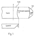
- Fig. 1 shows three-direction projection views of a cradle around its end portion on a side near the gantry apparatus, in which (a) is a top plan view of the cradle (a view from upside of a subject, if placed on the cradle), (b) is a front (end) view from the carrying direction (i.e., from the gantry apparatus), and (c) is a side view.
- the cross section of the cradle as viewed from the cross section or from the carrying direction has a bowl-like shape (inverted trapezoidal shape) whose top periphery forms a concave curve, as shown in the end view (b), so that the lying subject is stably supported.
- the cross section as viewed from the lateral side is formed as a shape cut at an end at an angle ⁇ , as shown in the side view (c). (The reason for the cut shape will be described later.)
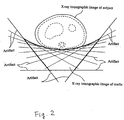
- Fig. 2 shows an exemplary X-ray tomographic image reconstructed by laying a subject on the illustrated cradle and scanning the subject at a position S shown in Fig. 1. (The scan plane is orthogonal to the drawing plane of Fig. 1.)
- the cradle is made from a material with a high X-ray transmission factor
- the reinforcing CFRP constituting the surface of the cradle has a lower transmission factor than the ambient air. Accordingly, many linear artifacts are generated along the tangential direction of the CFRP covering the surface, as shown in Fig. 2.
- the artifacts generated at the lateral surfaces of the cradle appear only in a direction away from the subject.
- the artifacts generated at the curved surface on which the subject is placed appear only in the tangential direction and do not enter the X-ray tomographic image of the subject. In these points, it may safely be said that these artifacts substantially do not affect a diagnosis based on the X-ray tomographic image in such a condition as shown in Fig. 2.
- a principal cause of artifacts is the existence of a material with a low X-ray transmission factor in a scan plane. Therefore, if the end surface of the cradle is not slanted but, unlike that shown in Fig. 1, is perpendicular, artifacts are generated when a position that coincides with the perpendicular end surface is scanned, because a CFRP layer having a low X-ray transmission factor extends in a plane that coincides with the scan plane. Hence, the surface at the end portion of the cradle is made slanted as shown in the side view Fig. 1(c).
- the angle ⁇ should be larger than a certain value. This is because a scan may possibly be performed with the gantry apparatus tilted by a certain angle ⁇ 0, rather than always being performed in a plane orthogonal to the carrying direction of the cradle, as shown in Fig. 3.
- the tilt is made because, for example, a range of vertebrae constituting the backbone of a human subject extends in a gentle S-shaped curve and an X-ray tomographic image sometimes needs to be reconstructed in a plane orthogonal to a certain portion in such a curved range.
- the slope angle ⁇ at the end portion of the cradle is smaller than the maximum tilt angle, there occurs a situation in which the tilt angle of the gantry is equal to ⁇ in an actual use, causing those artifacts described above to be generated.
- the slope angle ⁇ of the end surface of the cradle is required to be larger than the maximum tilt angle of the gantry apparatus.
- the gantry apparatus does not have a tilt function, a moderate angle will do without the above limitation on the angle.
- the end portion may support either the head or the feet of the subject.
- some cradles include a mechanism at the end portion for stably securing the head of the subject. This is achieved by inserting a head rest into an attachment slot provided at the end surface of the cradle, as shown in Fig. 4.
- a scan plane intersects two portions Pa and Pb at the corners of the cradle.
- the cross section of the scan plane is shown at "S-cross section" in Fig. 5, and two end cross sections Pa and Pb of the cradle are formed.
- bottom peripheries Pa1 and Pb1 of these cross sections are both horizontal, and in addition, are collinear. Consequently, artifacts are generated, or tend to be generated, on a line connecting the bottom peripheries Pa1 and Pb1. Therefore, if a certain site of the subject is placed at the end portion of the cradle, the artifact connecting the bottom peripheries Pa1 and Pb1 enters the X-ray tomographic image, as shown in Fig. 5, preventing an accurate diagnosis.
- the present invention was made in consideration of such problems, and is directed to providing a cradle and an X-ray CT system for reducing artifacts entering an X-ray tomographic image of a subject in performing a scan at an end portion of the cradle, and offering a reliable diagnosis environment.
- a cradle for an X-ray CT system of the present invention has, in one embodiment, the following configuration: a cradle for placing thereon a subject in an X-ray CT system and for carrying the subject toward a scan position:
- artifacts entering an X-ray tomographic image of a subject can be reduced in performing a scan at an end portion of a cradle, and a reliable diagnosis environment can be offered.
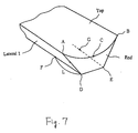
- Points A ⁇ G shown in Fig. 7 are defined as follows:
- Points A, C and F define a plane (which is a plane descending toward a direction opposite to the carrying direction).
- Points B, C and G define another similar plane.
- the shape of the end portion of the cradle in the present embodiment is formed by cutting the blank in these two planes.
- Fig. 8 shows three-direction projection views of the shape of the end portion of the cradle in the present embodiment.
- reference numerals A ⁇ C and F and G are the same as those shown in Fig. 7.
- the distance L may be set such that an angle ⁇ of a ridgeline R between the two cut surfaces with respect to the vertical surface is ⁇ shown in Fig. 1. The significance of the angle ⁇ was explained earlier and will not be repeated here.
- Fig. 9 shows the respective tomographic images of the portions Pa, Pb and Pc when a scan is performed at the position S0.
- Each of the portions Pa, Pb and Pc has a generally triangular shape as shown (though strictly speaking, the top periphery of each triangle is curved), and the fact that the bottom periphery Pa1 of the portion Pa and the bottom periphery Pc1 of the portion Pc are collinear should be noted.
- the reason for the collinearity is that the peripheries Pa1 and Pc1 are both on an intersection line between the plane defined by Points A, C and F described with reference to Fig. 7 and the scan plane at S1 in Fig. 8, i.e., on an intersection line between two planes.
- the bottom periphery Pb1 of the portion Pb and the bottom periphery Pc2 of the portion Pc are collinear.
- artifacts 40 and 41 are a line connecting the peripheries Pa1 and Pc1 and a line connecting the peripheries Pb1 and Pc2, respectively, shown in Fig. 9.
- the shape of the end portion of the cradle of the present embodiment can reduce artifacts entering the X-ray tomographic image of the subject, and a highly reliable X-ray tomographic image can be reconstructed throughout the length of the cradle.
- the cradle described according to this embodiment can be provided with an attachment slot for connecting the head rest as shown in Fig. 4. It is desirable that the shape of the slot be one for suppressing artifacts entering the X-ray tomographic image of the subject.
- the slot may simply have a cross-sectional shape homothetic to that of the cradle.
- the surface of the head rest abutting against the cradle may be formed in a shape that closely contacts the end surface of the cradle so as to reduce artifacts entering the X-ray tomographic image of the subject, even if artifacts are generated by the end surface of the head rest.
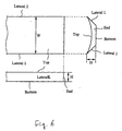
- the above embodiment has a shape obtained by cutting the cradle blank as shown in Fig. 6 in two planes.
- two artifacts lines 40 and 41 nearest to the X-ray tomographic image of the subject shown in Fig. 10 lie above the curved top surface of the cradle at a very small distance, i.e., enter the X-ray tomographic image of the subject.
- Reduction of the amount of entry can be achieved by a shape obtained by cutting the blank shown in Fig. 6 in three planes or more.
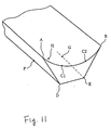
- Fig. 11 illustrates these positions for the blank shown in Fig. 6.
- Points A, B and D ⁇ G are the same as those shown in Fig. 7, and explanation thereof will be omitted.
- Points C1, C2 and H are defined as follows:
- the blank is cut in a surface defined by Points A, C1, and F, a plane defined by Points C1, C2 and H and a plane defined by Points B, C2 and G.
- the shape after cutting forms the end portion of the cradle in the second embodiment.
- Fig. 12 shows three-direction projection views of the cradle in accordance with the second embodiment.
- Point H is not necessarily the midpoint on a line connecting Points F and G, and it may lie nearer to the periphery DE. The essential thing is to assuredly maintain the angle ⁇ of the end surface with respect to the vertical plane.
- the number of artifacts entering an X-ray tomographic image of a subject can be reduced more than in the cradle of the first embodiment.
- Points C, C1 and C2 on a minimal curve connecting Points A and B on the top surface are described as dividing the curve into equal portions with reference to Figs. 7 and 11, these points are not limited thereto, and the number of the points is not limited to one or two but may be more.
Landscapes
- Health & Medical Sciences (AREA)
- Life Sciences & Earth Sciences (AREA)
- Medical Informatics (AREA)
- Engineering & Computer Science (AREA)
- Radiology & Medical Imaging (AREA)
- Biomedical Technology (AREA)
- Biophysics (AREA)
- Nuclear Medicine, Radiotherapy & Molecular Imaging (AREA)
- Optics & Photonics (AREA)
- Pathology (AREA)
- Physics & Mathematics (AREA)
- High Energy & Nuclear Physics (AREA)
- Heart & Thoracic Surgery (AREA)
- Molecular Biology (AREA)
- Surgery (AREA)
- Animal Behavior & Ethology (AREA)
- General Health & Medical Sciences (AREA)
- Public Health (AREA)
- Veterinary Medicine (AREA)
- Apparatus For Radiation Diagnosis (AREA)
Abstract
Description
a cradle for placing thereon a subject in an X-ray CT system and for carrying the subject toward a scan position:
Thus, artifacts generated also come closer to the curved top surface, extending in a direction away from the X-ray tomographic image of the subject.
Claims (11)
- A cradle for placing thereon a subject in an X-ray CT system and for carrying the subject toward a scan position:which has a top surface for placing the subject thereon that forms a concave curve as viewed from the carrying direction;which has a generally bowl-like shape in a cross section as viewed from the carrying direction; andrepresenting points at the same position with respect to said carrying direction on two peripheries along which said top surface and two lateral surfaces abut as A and B, and n points on a minimal curve connecting Points A and B on said top surface as C1, ..., Cn,which has at an end portion a shape that is cut in a plane passing through Points A and C1 and descending toward a direction opposite to the carrying direction, is cut in a plane passing through Points Ci and Ci+1 and descending toward a direction opposite to said carrying direction, and is cut in a plane passing through Points B and Cn and descending toward a direction opposite to said carrying direction.
- The cradle as recited in claim 1, wherein the number of said points on the minimal curve connecting Points A and B is one.
- The cradle as recited in claim 1, wherein the number of said points on the minimal curve connecting Points A and B is two.
- The cradle as recited in claim 1, 2 or 3, comprising a head rest portion attached to the surface having a generally bowl-like shape on a side of said cradle in the carrying direction.
- The cradle as recited in claim 4, wherein an attachment surface of said head rest portion against said cradle has a shape fitting the surface having a generally bowl-like shape of said cradle.
- The cradle as recited in claim 4 or 5, wherein said head rest portion has a top surface forming a concave curve as viewed from the carrying direction for placing the subject thereon.
- The cradle as recited in claim 4, 5 or 6, wherein the attachment surface of said head rest portion against said cradle is provided with a protruding portion, and an attachment surface of said cradle facing said head rest portion is provided with a slot portion for receiving said protruding portion.
- The cradle as recited in claim 7, wherein said slot portion provided in the attachment surface of said cradle facing said head rest portion has a cross-sectional shape homothetic to the cross-sectional shape of said cradle.
- The cradle as recited in claim 1, 2 or 3, wherein said cradle is formed from a foam material enclosed by carbon fiber reinforced plastic.
- The cradle as recited in claim 9, wherein said foam material is acrylic resin.
- An X-ray CT system comprising a cradle as recited in any one of claims 1 to 10.
Applications Claiming Priority (2)
| Application Number | Priority Date | Filing Date | Title |
|---|---|---|---|
| JP2000051837A JP4248723B2 (en) | 2000-02-28 | 2000-02-28 | X-ray CT system cradle and X-ray CT system |
| JP2000051837 | 2000-02-28 |
Publications (2)
| Publication Number | Publication Date |
|---|---|
| EP1127548A2 true EP1127548A2 (en) | 2001-08-29 |
| EP1127548A3 EP1127548A3 (en) | 2002-08-28 |
Family
ID=18573439
Family Applications (1)
| Application Number | Title | Priority Date | Filing Date |
|---|---|---|---|
| EP01301822A Withdrawn EP1127548A3 (en) | 2000-02-28 | 2001-02-28 | Cradle for X-ray CT system and X-ray CT system |
Country Status (5)
| Country | Link |
|---|---|
| US (1) | US6452999B1 (en) |
| EP (1) | EP1127548A3 (en) |
| JP (1) | JP4248723B2 (en) |
| KR (1) | KR20010085634A (en) |
| CN (1) | CN1318348A (en) |
Families Citing this family (13)
| Publication number | Priority date | Publication date | Assignee | Title |
|---|---|---|---|---|
| ES2283624T3 (en) | 2001-10-30 | 2007-11-01 | Loma Linda University Medical Center | DEVICE TO ALIGN A PATIENT FOR THE ADMINISTRATION OF RADIOTHERAPY. |
| JP3860996B2 (en) * | 2001-11-19 | 2006-12-20 | ジーイー・メディカル・システムズ・グローバル・テクノロジー・カンパニー・エルエルシー | Gantry system, X-ray CT system and control method thereof |
| US6969193B1 (en) | 2002-11-12 | 2005-11-29 | Modern Way Immobilizers, Inc. | Foot immobilizer |
| KR101081839B1 (en) | 2003-08-12 | 2011-11-09 | 로마 린다 유니버시티 메디칼 센터 | Modular patient support system |
| AU2004266644B2 (en) | 2003-08-12 | 2009-07-16 | Vision Rt Limited | Patient positioning system for radiation therapy system |
| US7073508B2 (en) | 2004-06-25 | 2006-07-11 | Loma Linda University Medical Center | Method and device for registration and immobilization |
| US7017209B1 (en) | 2005-03-14 | 2006-03-28 | Medtec, Inc. | Curved wing board for a CT cradle |
| US7740016B1 (en) | 2005-06-28 | 2010-06-22 | Modern Way Immobilizers, Inc. | Ankle and foot immobilizer |
| JP5448831B2 (en) | 2006-11-21 | 2014-03-19 | ローマ リンダ ユニヴァーシティ メディカル センター | Apparatus and method for securing a patient for breast radiation therapy |
| JP5623163B2 (en) * | 2010-07-08 | 2014-11-12 | 株式会社日立メディコ | Bed apparatus and X-ray CT apparatus including the same |
| DE202011000319U1 (en) * | 2011-02-11 | 2011-09-02 | Maquet Gmbh & Co. Kg | X-rayable patient support plate |
| DE102014222061A1 (en) * | 2014-10-29 | 2016-05-04 | Siemens Aktiengesellschaft | Lying board and patient bed for medical imaging procedures |
| WO2020245501A1 (en) * | 2019-06-03 | 2020-12-10 | Planmeca Oy | Ct imaging apparatus |
Family Cites Families (8)
| Publication number | Priority date | Publication date | Assignee | Title |
|---|---|---|---|---|
| US4727328A (en) * | 1985-11-15 | 1988-02-23 | Technicare Corporation | Patient handling arrangements for NMR imaging systems |
| JPS62201141A (en) * | 1986-02-28 | 1987-09-04 | 株式会社東芝 | Object support apparatus for medical diagnostic apparatus |
| JPH02246936A (en) * | 1989-03-22 | 1990-10-02 | Toshiba Corp | Bed device for x-ray ct |
| DE4416202C2 (en) * | 1994-05-06 | 2003-08-21 | Siemens Ag | Patient positioning device and use of the same |
| JPH08117218A (en) * | 1994-10-25 | 1996-05-14 | Ge Yokogawa Medical Syst Ltd | Inter-image calculation method and CT device |
| US5555284A (en) * | 1994-12-16 | 1996-09-10 | Kishigami; Yoshihiro | Roentgenography of vertebral column and the devices used therefor |
| US5619763A (en) * | 1995-03-24 | 1997-04-15 | Siemens Medical Systems, Inc. | Patient handling system for diagnostic imaging application |
| JP4024323B2 (en) * | 1996-02-21 | 2007-12-19 | 株式会社東芝 | Medical device top plate |
-
2000
- 2000-02-28 JP JP2000051837A patent/JP4248723B2/en not_active Expired - Fee Related
-
2001
- 2001-01-25 US US09/770,043 patent/US6452999B1/en not_active Expired - Fee Related
- 2001-02-27 KR KR1020010009837A patent/KR20010085634A/en not_active Withdrawn
- 2001-02-28 EP EP01301822A patent/EP1127548A3/en not_active Withdrawn
- 2001-02-28 CN CN01111944A patent/CN1318348A/en active Pending
Also Published As
| Publication number | Publication date |
|---|---|
| EP1127548A3 (en) | 2002-08-28 |
| JP4248723B2 (en) | 2009-04-02 |
| US20020027969A1 (en) | 2002-03-07 |
| JP2001245879A (en) | 2001-09-11 |
| US6452999B1 (en) | 2002-09-17 |
| CN1318348A (en) | 2001-10-24 |
| KR20010085634A (en) | 2001-09-07 |
Similar Documents
| Publication | Publication Date | Title |
|---|---|---|
| US6452999B1 (en) | Cradle for X-ray CT system and X-ray CT system | |
| US6229869B1 (en) | Tilted gantry image correction for a multislice computed tomography system | |
| EP1008325B1 (en) | X-ray computerized tomograph having collimator which restricts the irradiation range of x-ray fan beam | |
| US6879657B2 (en) | Computed tomography system with integrated scatter detectors | |
| US7632015B2 (en) | CT scanner including device to visually indicate area of CT scan | |
| US5054049A (en) | Patient support means for x-ray absorption compensation in computer tomography system | |
| EP1114617B1 (en) | Methods and apparatus for automatic patient positioning | |
| EP1149558A3 (en) | Apparatus for region of interest multislice CT scan | |
| US20040120467A1 (en) | System and method for table/gantry alignment in imaging systems | |
| US7486765B2 (en) | Image processing device and image processing method | |
| CN1675656B (en) | Method and apparatus for reconstruction of tilted gantry computed tomography | |
| EP0383232A3 (en) | Computerized tomographic apparatus | |
| US20090296880A1 (en) | Distortion correction method for linear scanning x-ray system | |
| US5572568A (en) | X-ray diagnostic table capable of displaying a center of an X-ray visual field | |
| US6987827B2 (en) | Apparatus and method for X-ray computer tomography | |
| JP2001299739A (en) | Method and apparatus for selecting retrospective reconstruction parameters | |
| EP2767238A1 (en) | Automatic field-of-view size calculation constraint | |
| US7062007B2 (en) | Tomography device | |
| CN103501704A (en) | Computed tomography device | |
| US20030063786A1 (en) | Image reconstruction method and X-ray CT apparatus | |
| JP5562021B2 (en) | X-ray CT system | |
| JPH08117218A (en) | Inter-image calculation method and CT device | |
| JP2004208952A (en) | X-ray ct system and image processing method in the ct system | |
| KR101386062B1 (en) | Gantry positioning apparatus and image obtaining apparatus using the same | |
| JPS6311014B2 (en) |
Legal Events
| Date | Code | Title | Description |
|---|---|---|---|
| PUAI | Public reference made under article 153(3) epc to a published international application that has entered the european phase |
Free format text: ORIGINAL CODE: 0009012 |
|
| AK | Designated contracting states |
Kind code of ref document: A2 Designated state(s): AT BE CH CY DE DK ES FI FR GB GR IE IT LI LU MC NL PT SE TR |
|
| AX | Request for extension of the european patent |
Free format text: AL;LT;LV;MK;RO;SI |
|
| PUAL | Search report despatched |
Free format text: ORIGINAL CODE: 0009013 |
|
| AK | Designated contracting states |
Kind code of ref document: A3 Designated state(s): AT BE CH CY DE DK ES FI FR GB GR IE IT LI LU MC NL PT SE TR |
|
| AX | Request for extension of the european patent |
Free format text: AL;LT;LV;MK;RO;SI |
|
| STAA | Information on the status of an ep patent application or granted ep patent |
Free format text: STATUS: THE APPLICATION HAS BEEN WITHDRAWN |
|
| 17P | Request for examination filed |
Effective date: 20030228 |
|
| AKX | Designation fees paid |
Designated state(s): DE FR GB |
|
| 18W | Application withdrawn |
Effective date: 20030410 |