EP1126917B1 - Sealing mat for closing reaction tubes - Google Patents
Sealing mat for closing reaction tubes Download PDFInfo
- Publication number
- EP1126917B1 EP1126917B1 EP00963139A EP00963139A EP1126917B1 EP 1126917 B1 EP1126917 B1 EP 1126917B1 EP 00963139 A EP00963139 A EP 00963139A EP 00963139 A EP00963139 A EP 00963139A EP 1126917 B1 EP1126917 B1 EP 1126917B1
- Authority
- EP
- European Patent Office
- Prior art keywords
- sealing
- carrier sheet
- sealing elements
- mat
- test tubes
- Prior art date
- Legal status (The legal status is an assumption and is not a legal conclusion. Google has not performed a legal analysis and makes no representation as to the accuracy of the status listed.)
- Expired - Lifetime
Links
Images


Classifications
-
- B—PERFORMING OPERATIONS; TRANSPORTING
- B01—PHYSICAL OR CHEMICAL PROCESSES OR APPARATUS IN GENERAL
- B01L—CHEMICAL OR PHYSICAL LABORATORY APPARATUS FOR GENERAL USE
- B01L3/00—Containers or dishes for laboratory use, e.g. laboratory glassware; Droppers
- B01L3/50—Containers for the purpose of retaining a material to be analysed, e.g. test tubes
- B01L3/508—Containers for the purpose of retaining a material to be analysed, e.g. test tubes rigid containers not provided for above
- B01L3/5082—Test tubes per se
- B01L3/50825—Closing or opening means, corks, bungs
Definitions
- the invention relates to a sealing mat for sealing test tubes, in particular to a sealing mat according to the preamble of claim 1.
- Sealing mats for sealing a multiplicity of test tubes are known in practice.
- the carrier sheet and the sealing elements are made as an integral whole from one material and permanently joined to one another.
- Such sealing mats are used in particular with storage and reagent means, such as test tubes (also termed microtubes), microtitration plates and "Deepwell” blocks (these are test tubes permanently joined to one another).
- test tubes also termed microtubes
- microtitration plates microtitration plates
- Deepwell these are test tubes permanently joined to one another.
- the test tubes are in general grouped in a cluster in accordance with an 8 x 12 matrix pattern.
- a major advantage of such mats is that it is possible by this means as it were to open and to seal a large number of test tubes at the same time in a single operation.
- One disadvantage of the known sealing mat, amongst others, is that opening the test tubes is not always equally easy.
- the sealing elements sometimes have the tendency to remain firmly seated in the test tubes, in which case a substantial force then has to be exerted on the mat in order to remove the mat, under the influence of which force the mat has the tendency to stretch and also to lift the tube concerned, and also other tubes, out of the rack.
- Another disadvantage is that soiling or contamination can occur in other test tubes when the sealing mat is removed.
- a further major disadvantage is that all test tubes have to be opened in order to gain access to one test tube.
- tools must be used if an individual (single) sealing element has to be fitted.
- test tube is to be understood to be a container for storing substances, either in liquid form, powder form, solid form or in combinations thereof, for the purposes of chemical analyses, sample storage, performing chemical reactions in the test tube, etc.
- Such test tubes can have sizes ranging from small test tubes, such as so-called “microtubes” with a capacity of the order of 0.2 ml (or possibly less), to large test tubes having a capacity of 10 ml or more.
- a test tube must also be understood to be composite storage and reagent means, such as microtitration plates and Deepwell blocks.
- US-A 5 282 543 discloses a sealing mat according to the preamble of claim 1, for sealing test tubes placed in a matrix pattern.
- the sealing mat consists of a sheet-like body that joins together a number of nodules which act as sealing elements and are arranged in a matrix pattern corresponding to the test tubes.
- the sheet-like body is provided with passages diagonally between every two adjacent nodules in order to guarantee adequate circulation of air for the purposes of heat transfer from a contact block to the underside of the sheet-like body.
- the entire teaching of US-A 5 282 543 is directed towards the nodules being permanently attached to the sheet-like body.
- EP-A 0 836 884 discloses a sealing system consisting of so-called inner sealing means and outer sealing means.
- the inner sealing means consist of cylindrical components which are to be placed within the open top end of a test tube and are sealed at their tops by a flat plate-like component having therein an optionally open, pre-formed passage for the point of a pipette.
- a number of inner sealing means are joined to one another by joining strips to give a matrix-like pattern. In this case there is no question of a carrier sheet and EP-A 0 863 884 also does not teach that the inner sealing means can be separated from one another.
- the passages in the inner sealing means EP-A 0 836 884 provides outer sealing means in the form of a large sheet that is placed over the test tubes provided with inner sealing means and is pressed down onto these to produce a seal.
- this large sheet is not a carrier sheet for the cylindrical components of the inner sealing means.
- the aim of the present invention is to provide an improved sealing mat for sealing test-tubes, in which the join between sealing elements and carrier sheet can be produced simply and reliably.
- This aim is achieved according to the invention by providing a sealing mat according to claim 1.
- a sealing mat according to claim 1.
- the carrier sheet and the sealing elements for the sealing mat of different materials it becomes possible, inter alia, to use one material for the sealing elements, which, on the one hand, has very good sealing properties, and to use a material for the carrier sheet which, on the other hand, has properties which are favourable with respect to removing the sealing mat from the test tubes.
- These sealing properties on the one hand and removal properties on the other hand can then be mutually incompatible.
- the carrier sheet and the sealing elements for the sealing mat of different materials it becomes possible to assign another material to one of the elements, without the characteristics of the other material being affected. Examples are different colourings or different chemical resistance.
- making the carrier sheet, on the one hand, and the sealing elements, on the other hand, of different materials also offers yet further advantages. Since the sealing elements have to seal test tubes, special requirements are generally imposed on these in connection with chemical resistance.
- the sealing elements have a good sealing action it is advantageous, according to the invention, if the sealing elements are made from a flexible and/or resilient material. This makes a close fitting seal of the sealing element on the test tube possible.
- the sealing elements are attached to the carrier sheet such that they can be removed.
- this makes it possible to be able to open, independently of one another, the test tubes sealed by means of the sealing elements.
- the carrier sheet can, for example, be removed, after which each of the test tubes is individually sealed and can also be moved individually in the sealed state.
- the sealing elements are attached to a carrier sheet in such a way that they detach from the carrier sheet when the latter is pulled back, while folding it over towards the rear, after sealing one or more test tubes. Pulling the carrier sheet back while folding it over towards the rear, that is to say pulling it back in a direction essentially transverse to the longitudinal direction of the test tubes, prevents a force acting in the longitudinal direction being exerted on the test tubes, which force could lift the test tubes from their container or rack.
- the sealing mat with which sealing elements are detachably attached to the carrier sheet has the additional advantage that said mat can be employed more easily in an automated process.
- guides are therefore also provided on opposing sides of the mat.
- the peripheral groove is formed just below the top end of the sealing element.
- “just below” is understood to be such that the sealing element is still able to overlap the carrier sheet at the top.
- the distance from the top of the groove to the top of the sealing element will in general be of the same order of magnitude as the thickness of the carrier sheet, for example 0.25 to 4 times the thickness of said carrier sheet. It is possible, for example, to make the distance from the top of the peripheral groove to the top of the sealing element equal to the thickness of the carrier sheet.
- this distance will then be 0.3 mm, or "just below” in this example must be taken to read 0.3 mm below the top end.
- this provision of the peripheral groove just below the top end of the sealing element offers the advantage that the sealing element can be pulled away from the carrier sheet relatively easily in the downward direction relative to the carrier sheet.
- the small overlapping thickness of the sealing element which is of the order of magnitude of the thickness of the carrier sheet, will then easily be able to give in order to be able to pull the sealing element from the carrier sheet.
- this "detachability" functions particularly well if the sealing elements have been made from a relatively flexible material, it being possible for the carrier sheet then to have been made from a relatively rigid, or optionally even also flexible, material.
- the sealing element In order to counteract the carrier sheet accidentally being able to detach from the sealing element in the downward direction over said sealing element (if, for example, the sealing element is restrained and downward force is exerted on the carrier sheet), it is advantageous if the bottom face of the peripheral groove is continued further in the outward direction than is the top face of the peripheral groove.
- the sealing element thus provides a larger support surface for the carrier sheet in the downward direction, whilst said carrier sheet can still be detached from the sealing element in the upward direction.
- the sealing elements can be of solid construction, but according to the invention it is advantageous if the sealing elements are caps, in particular caps which are hollow on the inside and open at the top, which are suitable for accommodating in the open end of the test tubes with an open end facing up. In this way the sealing element is more suitable for puncturing with a needle in order to gain access to the contents of the test tube. Because use is made of a carrier sheet containing holes, the needle will not have to puncture this carrier sheet, which also brings various advantages.
- the material to be used can be of diverse nature. The following aspects in particular can be taken into account.
- the sealing elements are made from a chemically resistant material.
- sealing elements which have good closing and sealing characteristics as well as chemical resistance are obtained if the sealing elements are made from a TPE (thermoplastic elastomer) or PP (polypropene).
- TPE thermoplastic elastomer
- PP polypropene
- the sealing elements are constructed such that they can be punctured by a needle, preferably relatively easily.
- the carrier sheet can advantageously be made from a PET (polyethene terephthalate) or PP (polypropene) material.
- Fig. 1 shows a container or rack 1 in which ninety-six test tubes 2, or, more accurately, so-called "microtubes" 2, have been placed in an 8 x 12 matrix pattern.
- the openings of these microtubes 2 are at the top and essentially in a flat plane.
- a sealing mat 3 consisting of a carrier sheet 4 with ninety-six cap-shaped sealing elements 5 has been placed on top of the microtubes 2.
- Each cap-shaped sealing element 5 has been pressed as a stopper into the open top of a microtube 2 in order that its side face 14 ( Figure 4) comes into contact with the inside wall of the microtube to provide a closure and a seal.
- the sealing mat 3 is further provided with a lip 6 that can serve as a grasping point for removal of the mat 3 or at least the carrier sheet 4.
- the sealing mat 3 could then be regarded as a sealing mat according to the prior art known in practice.
- the sealing elements 5 and the carrier sheet 4 are made from different materials, which different materials will have properties which differ from one another.
- “different materials” must also be understood as, for example, two PP materials which have different compositions and/or properties.
- the sheet and the sealing elements can both have been made from a PP material, but using a PP for the sheet that differs from that used for the sealing elements.
- an advantageous embodiment is found to be sealing elements made of a TPE on a PP carrier mat.
- the sealing elements 5 and the carrier sheet 4 it becomes possible, for example, to use a material for the sealing elements 5 that has very good properties with regard to sealing against the (inside) wall of the test tubes 2 and/or the chemical resistance and to make the carrier sheet 4 from a material that has very good properties in particular with regard to the removal of the sealing mat or at least the carrier sheet and optionally also fitting of the sealing mat, which good properties of a material for the carrier sheet and a material for the sealing elements can be completely incompatible with one another.
- a sealing mat that in respect of, inter alia, sealing, removal and fitting is appreciably better than that disclosed in the prior art.
- the sealing mat 3 according to the invention can be produced by taking a carrier sheet 4, for example a film having a thickness of less than 0.5 mm, as the starting point, punching a matrix of 8 x 12 openings in this carrier sheet 4 and then clamping this carrier sheet 4 between two mould halves of an injection moulding mould in such a way that the edge portions 8 around the openings 7 project into the mould cavities of the mould halves and are embedded in a groove 9, to be formed around said edge portions 8, when injection moulding the material for the sealing element 5. Enclosure of the edge portions 8 between a lower limiting surface 10 and an upper limiting surface 11 of the groove 9 is achieved in this way.
- a carrier sheet 4 for example a film having a thickness of less than 0.5 mm
- fusion of carrier sheet material and sealing element material may or may not then take place in the groove 9. If, for example, the sealing elements are made from a TPE and the carrier sheet 4 from a PP film fusion will in general then occur, whilst if the sealing elements are made from a TPE film and the carrier sheet from a PET film in general no mutual fusion but merely an enclosure or clamping will then take place.
- the sealing elements will in general not be detachable, or at least not easily detachable, from the carrier sheet.
- This embodiment is shown in Fig. 3.
- the sealing elements 5 will then all be removed from the test tubes or microtubes 2 more or less at the same time, at least in one operation, when a pull is exerted on the lip 7.
- the sealing elements 5 can then be detached from the carrier sheet 4, which has the advantage that test tubes can then be left behind which can all be handled individually in the sealed state.
- Fig. 2 Such an embodiment is shown in which, after detaching a portion of the carrier sheet 4, the openings 7 in which sealing elements 5 were seated are clearly visible.
- the carrier sheet can have been made from a PET and the sealing elements can have been made from a TPE.
- the carrier sheet 4 is accommodated a distance A just below the top 12 of the sealing element 5 in a peripheral groove 9 that extends in the peripheral direction about the axis 13 around the entire periphery of the sealing element 5 and that this distance A is of the same order of magnitude as the thickness B of the carrier sheet 4.
- the lower limiting surface 10 of the groove 9 extends further outwards with respect to the axis 13 than does the upper limiting surface 11 of the groove 9. In this way a support surface for the carrier sheet 4 in the downward direction is provided which is relatively larger than the support surface in the upward direction. This larger support surface 10 is particularly advantageous if the sealing elements 5 are removable from the carrier sheet 4.
- the essentially vertical flat portion 14 is the portion that essentially will provide the closing and seal at the inside wall of the test tube.
- the sealing elements 5 are constructed as caps having an internal cavity 15 open at the top.
- Diameter D is approximately 7.5 mm
- Distance A is approximately 0.3 mm
- Thickness B is approximately 0.3 mm
- Height H is approximately 4.8 mm
- Overlap E is approximately 0.3 mm.
- these dimensions will relate to microtubes having an opening diameter of approximately 7.5 mm. However, it will also be clear that these dimensions are merely indicative and that the sealing elements and the carrier sheet can also have other dimensions, which can be either larger or smaller dimensions, depending on the application.
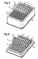
- Figure 5 shows a sealing mat according to Figure 2 used with a "Deepwell” block, that is to say the sealing mat of the type with which the sealing elements 5 are detachable from the carrier sheet 4.
- This "Deepwell” block that is indicated by 20 is, as it were, a block containing integral test tubes 21 (which thus cannot be removed from the block).
- the sealing mat according to Figure 3 that is to say the sealing mat of the type with which the sealing elements 5 are permanently joined to the carrier sheet 4, can also be used with a "Deepwell” block.
- Figure 6 shows a sealing mat according to Figure 3, that is to say the sealing mat of the type with which the sealing elements 5 are permanently joined to the carrier sheet 4, used with a "microtitration plate".
- the microtitration plate which is indicated by 20, is, as it were, a plate containing integral shallow test tubes 22 (which thus cannot be removed from the plate).
- the sealing mat according to Figure 2 that is to say the sealing mat of the type with which the sealing elements 5 are detachable from the carrier sheet 4, can also be used with a microtitration plate.
Abstract
Description
- The invention relates to a sealing mat for sealing test tubes, in particular to a sealing mat according to the preamble of claim 1.
- Sealing mats for sealing a multiplicity of test tubes are known in practice. In this known sealing mats the carrier sheet and the sealing elements are made as an integral whole from one material and permanently joined to one another. Such sealing mats are used in particular with storage and reagent means, such as test tubes (also termed microtubes), microtitration plates and "Deepwell" blocks (these are test tubes permanently joined to one another). In this case the test tubes are in general grouped in a cluster in accordance with an 8 x 12 matrix pattern. A major advantage of such mats is that it is possible by this means as it were to open and to seal a large number of test tubes at the same time in a single operation. One disadvantage of the known sealing mat, amongst others, is that opening the test tubes is not always equally easy. The sealing elements sometimes have the tendency to remain firmly seated in the test tubes, in which case a substantial force then has to be exerted on the mat in order to remove the mat, under the influence of which force the mat has the tendency to stretch and also to lift the tube concerned, and also other tubes, out of the rack. Another disadvantage is that soiling or contamination can occur in other test tubes when the sealing mat is removed. A further major disadvantage is that all test tubes have to be opened in order to gain access to one test tube. A further disadvantage is that tools must be used if an individual (single) sealing element has to be fitted.
- Within the scope of the invention a test tube is to be understood to be a container for storing substances, either in liquid form, powder form, solid form or in combinations thereof, for the purposes of chemical analyses, sample storage, performing chemical reactions in the test tube, etc. Such test tubes can have sizes ranging from small test tubes, such as so-called "microtubes" with a capacity of the order of 0.2 ml (or possibly less), to large test tubes having a capacity of 10 ml or more. Within the scope of the invention a test tube must also be understood to be composite storage and reagent means, such as microtitration plates and Deepwell blocks. US-A 5 282 543 discloses a sealing mat according to the preamble of claim 1, for sealing test tubes placed in a matrix pattern. According to a second embodiment of US-A 5 282 543, the sealing mat consists of a sheet-like body that joins together a number of nodules which act as sealing elements and are arranged in a matrix pattern corresponding to the test tubes. The sheet-like body is provided with passages diagonally between every two adjacent nodules in order to guarantee adequate circulation of air for the purposes of heat transfer from a contact block to the underside of the sheet-like body. The entire teaching of US-A 5 282 543 is directed towards the nodules being permanently attached to the sheet-like body.
- EP-A 0 836 884 discloses a sealing system consisting of so-called inner sealing means and outer sealing means. The inner sealing means consist of cylindrical components which are to be placed within the open top end of a test tube and are sealed at their tops by a flat plate-like component having therein an optionally open, pre-formed passage for the point of a pipette. A number of inner sealing means are joined to one another by joining strips to give a matrix-like pattern. In this case there is no question of a carrier sheet and EP-A 0 863 884 also does not teach that the inner sealing means can be separated from one another. For sealing, in particular, the passages in the inner sealing means EP-A 0 836 884 provides outer sealing means in the form of a large sheet that is placed over the test tubes provided with inner sealing means and is pressed down onto these to produce a seal. However, this large sheet is not a carrier sheet for the cylindrical components of the inner sealing means.
- The aim of the present invention is to provide an improved sealing mat for sealing test-tubes, in which the join between sealing elements and carrier sheet can be produced simply and reliably.
- This aim is achieved according to the invention by providing a sealing mat according to claim 1. As a result of making the carrier sheet and the sealing elements for the sealing mat of different materials it becomes possible, inter alia, to use one material for the sealing elements, which, on the one hand, has very good sealing properties, and to use a material for the carrier sheet which, on the other hand, has properties which are favourable with respect to removing the sealing mat from the test tubes. These sealing properties on the one hand and removal properties on the other hand can then be mutually incompatible. With this arrangement the production procedure can be as follows:
- A sheet having one opening per sealing element is first formed, for example by punching the desired number of openings in the desired positions in a sheet of suitable material. This sheet is then placed taut in an injection moulding mould, such that each opening is located at the position of the mould cavity for a sealing element The edge of the opening in the carrier sheet will then project somewhat into the mould cavity in order to be incorporated or embedded in the sealing element on injecting the material for that sealing element. Depending on, inter alia, the materials used for the sealing elements and the carrier sheet, the injection moulding temperature and the duration of the injection moulding process, as well as on possible other factors, the sealing elements and the carrier sheet can then fuse with one another during this operation in order to form an integral whole or the edge of the carrier sheet can merely be accommodated in the peripheral groove without entering into a direct join with the sealing element other than by enclosure in the peripheral groove.
-
- Other possible joins between the sealing elements and the carrier sheet are also conceivable, including clamping of the components on a mechanical basis or gluing in some other way. Permanent and completely loose joins can be produced by these means.
- By making the carrier sheet and the sealing elements for the sealing mat of different materials it becomes possible to assign another material to one of the elements, without the characteristics of the other material being affected. Examples are different colourings or different chemical resistance. However, making the carrier sheet, on the one hand, and the sealing elements, on the other hand, of different materials also offers yet further advantages. Since the sealing elements have to seal test tubes, special requirements are generally imposed on these in connection with chemical resistance.
- So that the sealing elements have a good sealing action it is advantageous, according to the invention, if the sealing elements are made from a flexible and/or resilient material. This makes a close fitting seal of the sealing element on the test tube possible.
- According to a particularly preferred embodiment of the sealing mat according to the invention it is highly advantageous if the sealing elements are attached to the carrier sheet such that they can be removed. In particular, this makes it possible to be able to open, independently of one another, the test tubes sealed by means of the sealing elements. After sealing the test tubes the carrier sheet can, for example, be removed, after which each of the test tubes is individually sealed and can also be moved individually in the sealed state.
- According to a particular further embodiment of the invention it is advantageous if the sealing elements are attached to a carrier sheet in such a way that they detach from the carrier sheet when the latter is pulled back, while folding it over towards the rear, after sealing one or more test tubes. Pulling the carrier sheet back while folding it over towards the rear, that is to say pulling it back in a direction essentially transverse to the longitudinal direction of the test tubes, prevents a force acting in the longitudinal direction being exerted on the test tubes, which force could lift the test tubes from their container or rack. The sealing mat with which sealing elements are detachably attached to the carrier sheet has the additional advantage that said mat can be employed more easily in an automated process. According to a further embodiment guides are therefore also provided on opposing sides of the mat.
- In order to make simple removal or detachment of the carrier sheet possible by pulling the latter away by folding over towards the rear in the case where the sealing elements have been detachably fixed to the carrier sheet, it is advantageous according to the invention if the peripheral groove is formed just below the top end of the sealing element. In this context "just below" is understood to be such that the sealing element is still able to overlap the carrier sheet at the top. With this arrangement the distance from the top of the groove to the top of the sealing element will in general be of the same order of magnitude as the thickness of the carrier sheet, for example 0.25 to 4 times the thickness of said carrier sheet. It is possible, for example, to make the distance from the top of the peripheral groove to the top of the sealing element equal to the thickness of the carrier sheet. If a 0.3 mm thick film is used for the carrier sheet this distance will then be 0.3 mm, or "just below" in this example must be taken to read 0.3 mm below the top end. Especially in the case where the sealing elements are detachably fixed to the carrier sheet and preferably are not fused to the latter, this provision of the peripheral groove just below the top end of the sealing element offers the advantage that the sealing element can be pulled away from the carrier sheet relatively easily in the downward direction relative to the carrier sheet. The small overlapping thickness of the sealing element, which is of the order of magnitude of the thickness of the carrier sheet, will then easily be able to give in order to be able to pull the sealing element from the carrier sheet. Although not absolutely necessary, it will be clear that this "detachability" functions particularly well if the sealing elements have been made from a relatively flexible material, it being possible for the carrier sheet then to have been made from a relatively rigid, or optionally even also flexible, material.
- In order to counteract the carrier sheet accidentally being able to detach from the sealing element in the downward direction over said sealing element (if, for example, the sealing element is restrained and downward force is exerted on the carrier sheet), it is advantageous if the bottom face of the peripheral groove is continued further in the outward direction than is the top face of the peripheral groove. The sealing element thus provides a larger support surface for the carrier sheet in the downward direction, whilst said carrier sheet can still be detached from the sealing element in the upward direction.
- The sealing elements can be of solid construction, but according to the invention it is advantageous if the sealing elements are caps, in particular caps which are hollow on the inside and open at the top, which are suitable for accommodating in the open end of the test tubes with an open end facing up. In this way the sealing element is more suitable for puncturing with a needle in order to gain access to the contents of the test tube. Because use is made of a carrier sheet containing holes, the needle will not have to puncture this carrier sheet, which also brings various advantages.
- The material to be used can be of diverse nature. The following aspects in particular can be taken into account.
- In order to counteract the contents of a test tube being able to enter into a reaction with a sealing element it is advantageous according to the invention if the sealing elements are made from a chemically resistant material.
- According to the invention, sealing elements which have good closing and sealing characteristics as well as chemical resistance are obtained if the sealing elements are made from a TPE (thermoplastic elastomer) or PP (polypropene).
- According to the invention it is particularly advantageous if the sealing elements are constructed such that they can be punctured by a needle, preferably relatively easily.
- According to the invention the carrier sheet can advantageously be made from a PET (polyethene terephthalate) or PP (polypropene) material.
- The present invention will be explained in more detail below with reference to illustrative embodiments shown in the drawing. In the drawing:
- Fig. 1 shows a diagrammatic, perspective view of a container containing ninety-six test tubes on which a sealing mat according to the invention has been placed;
- Fig. 2 shows a diagrammatic and perspective illustration of a sealing mat according to a first embodiment of the invention;
- Fig. 3 shows a diagrammatic and perspective view of an illustration of a sealing mat according to a second embodiment of the invention;
- Fig. 4 shows a diagrammatic sectional view of a detail of a sealing mat according to the invention, in particular a portion of the sealing mat at the location of a sealing element;
- Fig. 5 shows a diagrammatic and perspective view of an illustration of a sealing mat according to the invention used with a so-called "Deepwell" block; and
- Fig. 6 shows a diagrammatic and perspective view of an illustration of a sealing mat according to the invention used with a so-called microtitration plate.
-
- Before discussing the figures in more detail it is pointed out that what is shown in Figures 1 and 4 must be seen both in relation to the first embodiment according to Fig. 2 and in relation to the second embodiment according to Fig. 3. The sealing mat shown in its entirety in Fig. 1 and by means of a detail in Fig. 4 can thus, as far as what is visible immediately from the figures is concerned, relate both to the sealing mat according to Fig. 2 and the sealing mat according to Fig. 3. The reason is that the difference between the embodiment according to Fig. 2 and the embodiment according to Fig. 3 essentially results from the material used for the carrier sheet.
- Fig. 1 shows a container or rack 1 in which ninety-six test tubes 2, or, more accurately, so-called "microtubes" 2, have been placed in an 8 x 12 matrix pattern. The openings of these microtubes 2 are at the top and essentially in a flat plane. A sealing
mat 3 consisting of acarrier sheet 4 with ninety-six cap-shapedsealing elements 5 has been placed on top of the microtubes 2. Each cap-shapedsealing element 5 has been pressed as a stopper into the open top of a microtube 2 in order that its side face 14 (Figure 4) comes into contact with the inside wall of the microtube to provide a closure and a seal. The sealingmat 3 is further provided with alip 6 that can serve as a grasping point for removal of themat 3 or at least thecarrier sheet 4. - If the
carrier sheet 4 and the sealing caps 5 in the embodiment shown in Fig. 3 were to be made as an integral whole from one and the same material, the sealingmat 3 could then be regarded as a sealing mat according to the prior art known in practice. - However, according to the invention in the embodiment according to Figure 3 the
sealing elements 5 and thecarrier sheet 4 are made from different materials, which different materials will have properties which differ from one another. Thus, "different materials" must also be understood as, for example, two PP materials which have different compositions and/or properties. In the case of the example shown in Fig. 3 the sheet and the sealing elements can both have been made from a PP material, but using a PP for the sheet that differs from that used for the sealing elements. - However, an advantageous embodiment is found to be sealing elements made of a TPE on a PP carrier mat.
- As a result of using different materials for the
sealing elements 5 and thecarrier sheet 4, in accordance with the invention, it becomes possible, for example, to use a material for thesealing elements 5 that has very good properties with regard to sealing against the (inside) wall of the test tubes 2 and/or the chemical resistance and to make thecarrier sheet 4 from a material that has very good properties in particular with regard to the removal of the sealing mat or at least the carrier sheet and optionally also fitting of the sealing mat, which good properties of a material for the carrier sheet and a material for the sealing elements can be completely incompatible with one another. Thus, it becomes possible to obtain a sealing mat that in respect of, inter alia, sealing, removal and fitting is appreciably better than that disclosed in the prior art. - With reference to Figure 4, which is shown on a larger scale, the sealing
mat 3 according to the invention can be produced by taking acarrier sheet 4, for example a film having a thickness of less than 0.5 mm, as the starting point, punching a matrix of 8 x 12 openings in thiscarrier sheet 4 and then clamping thiscarrier sheet 4 between two mould halves of an injection moulding mould in such a way that theedge portions 8 around theopenings 7 project into the mould cavities of the mould halves and are embedded in agroove 9, to be formed around saidedge portions 8, when injection moulding the material for the sealingelement 5. Enclosure of theedge portions 8 between a lower limitingsurface 10 and an upper limiting surface 11 of thegroove 9 is achieved in this way. Depending on the conditions during the injection moulding process and/or the materials used for thecarrier sheet 4 and thesealing elements 5 and/or other conditions, fusion of carrier sheet material and sealing element material may or may not then take place in thegroove 9. If, for example, the sealing elements are made from a TPE and thecarrier sheet 4 from a PP film fusion will in general then occur, whilst if the sealing elements are made from a TPE film and the carrier sheet from a PET film in general no mutual fusion but merely an enclosure or clamping will then take place. - If fusion takes place between the carrier sheet material and the sealing element material, the sealing elements will in general not be detachable, or at least not easily detachable, from the carrier sheet. This embodiment is shown in Fig. 3. As is shown diagrammatically in this figure, the sealing
elements 5 will then all be removed from the test tubes or microtubes 2 more or less at the same time, at least in one operation, when a pull is exerted on thelip 7. - If no fusion takes place between the
carrier sheet material 4 and the sealingelement material 5 or only low strength fusion takes place between them, the sealingelements 5 can then be detached from thecarrier sheet 4, which has the advantage that test tubes can then be left behind which can all be handled individually in the sealed state. Such an embodiment is shown in Fig. 2, in which, after detaching a portion of thecarrier sheet 4, theopenings 7 in whichsealing elements 5 were seated are clearly visible. In the embodiment according to Fig. 2 the carrier sheet can have been made from a PET and the sealing elements can have been made from a TPE. - Again with reference to Fig. 4, it can be seen that the
carrier sheet 4 is accommodated a distance A just below the top 12 of the sealingelement 5 in aperipheral groove 9 that extends in the peripheral direction about the axis 13 around the entire periphery of the sealingelement 5 and that this distance A is of the same order of magnitude as the thickness B of thecarrier sheet 4. It can also be seen that the lower limitingsurface 10 of thegroove 9 extends further outwards with respect to the axis 13 than does the upper limiting surface 11 of thegroove 9. In this way a support surface for thecarrier sheet 4 in the downward direction is provided which is relatively larger than the support surface in the upward direction. Thislarger support surface 10 is particularly advantageous if thesealing elements 5 are removable from thecarrier sheet 4. Specifically, in this way it is possible to counteract thecarrier sheet 4 coming out of thegroove 9 in the downward direction as a result of pressing on thecarrier sheet 4 or on anadjacent sealing element 5, which in such a case could be unintentional and could occur when pressing an adjacent or neighbouring sealingelement 5, or at least to make this more difficult. The overlap with thecarrier sheet 4 is relatively small at the upper limiting surface 11 compared with the overlap with the lower limitingsurface 10, which facilitates removal of the sealingelement 5 from thecarrier sheet 4, certainly if the sealingelement 5 has been made from a relatively flexible, compliant material that is particularly very suitable for the sealing action in a test tube. This construction makes it possible in particular, as is shown diagrammatically in Fig. 2, to pull thecarrier sheet 4 back and away in the manner termed "folding over towards to the rear" in the direction of arrow C more or less parallel to the plane in which the openings of the test tubes 2 are located. This pulling back and away will be easy to carry out especially in the case of a relativelyrigid carrier sheet 4, leaving thesealing elements 5 behind in the test tubes 2. - With reference to Fig. 4 it is also pointed out that the essentially vertical
flat portion 14 is the portion that essentially will provide the closing and seal at the inside wall of the test tube. On the grounds of, on the one hand, considerations with regard to saving of material and, on the other hand, considerations of functionality, the sealingelements 5 are constructed as caps having aninternal cavity 15 open at the top. - The following dimensions are given merely by way of indication of the dimensions which a sealing element of a sealing mat according to the invention could have, as far as the embodiment shown in Fig. 4 is concerned:
Diameter D is approximately 7.5 mm Distance A is approximately 0.3 mm Thickness B is approximately 0.3 mm Height H is approximately 4.8 mm Overlap E is approximately 0.3 mm. - It will be clear that these dimensions will relate to microtubes having an opening diameter of approximately 7.5 mm. However, it will also be clear that these dimensions are merely indicative and that the sealing elements and the carrier sheet can also have other dimensions, which can be either larger or smaller dimensions, depending on the application.
- Figure 5 shows a sealing mat according to Figure 2 used with a "Deepwell" block, that is to say the sealing mat of the type with which the
sealing elements 5 are detachable from thecarrier sheet 4. This "Deepwell" block that is indicated by 20 is, as it were, a block containing integral test tubes 21 (which thus cannot be removed from the block). However, it will be clear that the sealing mat according to Figure 3, that is to say the sealing mat of the type with which thesealing elements 5 are permanently joined to thecarrier sheet 4, can also be used with a "Deepwell" block. - Figure 6 shows a sealing mat according to Figure 3, that is to say the sealing mat of the type with which the
sealing elements 5 are permanently joined to thecarrier sheet 4, used with a "microtitration plate". The microtitration plate, which is indicated by 20, is, as it were, a plate containing integral shallow test tubes 22 (which thus cannot be removed from the plate). However, it will be clear that the sealing mat according to Figure 2, that is to say the sealing mat of the type with which thesealing elements 5 are detachable from thecarrier sheet 4, can also be used with a microtitration plate.
Claims (12)
- Sealing mat (3) comprising a carrier sheet (4) provided with a multiplicity of sealing elements (5) for sealing test tubes (2), the carrier sheet (4), on the one hand, and the sealing elements (5), on the other hand, being made of different materials, such as plastics, characterised in that the sealing elements (5) are provided with a peripheral groove (9) in which the edge (8) of an opening made in the carrier sheet (4) has been accommodated.
- Sealing mat (3) according to Claim 1, characterised in that the sealing elements (5) are made from a flexible and/or resilient material.
- Sealing mat (3) according to one of the preceding claims, characterised in that the sealing elements (5) are detachably fixed to the carrier sheet (4).
- Sealing mat (3) according to one of the preceding claims, characterised in that the sealing elements (5) are attached to the carrier sheet (4) in such a way that they detach from the carrier sheet (4) when the latter is pulled away, while folding it over towards the rear, after sealing one or more test tubes (2).
- Sealing mat (3) according to one of the preceding claims, characterised in that the peripheral groove (9) has been made just below the top end of the sealing element (5).
- Sealing mat according to one of the preceding claims, characterised in that the bottom face (10) of the peripheral groove (9) has been continued further in the outward direction than has the top face (11) of the peripheral groove (9).
- Sealing mat (3) according to one of the preceding claims, characterised in that the sealing elements (5) are caps for fitting in the open end of the test tubes(2), such as microtubes.
- Sealing mat (3) according to one of the preceding claims, characterised in that the sealing elements (5) are made of a chemically resistant material.
- Sealing mat (3) according to one of the preceding claims, characterised in that the sealing elements (5) are made from a TPE (thermoplastic elastomer), in particular a TPE that can be punctured by a needle.
- Sealing mat (3) according to one of the preceding claims, characterised in that the carrier sheet (4) is made from a PET (polyethene terephthalate) or PP (polypropylene).
- Sealing mat (3) according to one of the preceding claims, characterised in that the sealing elements (5) are arranged on the carrier sheet (4) in accordance with a matrix pattern, for example an 8 x 12 matrix pattern.
- use of a sealing mat (3) according to one of the preceding claims, for sealing microtubes (2).
Applications Claiming Priority (3)
| Application Number | Priority Date | Filing Date | Title |
|---|---|---|---|
| NL1012996 | 1999-09-08 | ||
| NL1012996A NL1012996C2 (en) | 1999-09-08 | 1999-09-08 | Sealing mat for sealing test tubes. |
| PCT/NL2000/000631 WO2001017682A1 (en) | 1999-09-08 | 2000-09-07 | Sealing mat for closing reaction tubes |
Publications (2)
| Publication Number | Publication Date |
|---|---|
| EP1126917A1 EP1126917A1 (en) | 2001-08-29 |
| EP1126917B1 true EP1126917B1 (en) | 2005-11-23 |
Family
ID=19769839
Family Applications (1)
| Application Number | Title | Priority Date | Filing Date |
|---|---|---|---|
| EP00963139A Expired - Lifetime EP1126917B1 (en) | 1999-09-08 | 2000-09-07 | Sealing mat for closing reaction tubes |
Country Status (8)
| Country | Link |
|---|---|
| US (1) | US6776964B1 (en) |
| EP (1) | EP1126917B1 (en) |
| JP (1) | JP3633900B2 (en) |
| AT (1) | ATE310583T1 (en) |
| AU (1) | AU7459000A (en) |
| DE (1) | DE60024219D1 (en) |
| NL (1) | NL1012996C2 (en) |
| WO (1) | WO2001017682A1 (en) |
Cited By (1)
| Publication number | Priority date | Publication date | Assignee | Title |
|---|---|---|---|---|
| EP2520369A1 (en) | 2011-05-05 | 2012-11-07 | Eppendorf AG | Method and laboratory apparatus for processing laboratory samples |
Families Citing this family (25)
| Publication number | Priority date | Publication date | Assignee | Title |
|---|---|---|---|---|
| US20050226786A1 (en) * | 2001-03-08 | 2005-10-13 | Hager David C | Multi-well apparatus |
| US6890488B2 (en) * | 2001-06-22 | 2005-05-10 | Matrix Technologies, Inc. | Apparatus for sealing test tubes and the like |
| WO2003015918A2 (en) * | 2001-08-16 | 2003-02-27 | Weidmann Plastics Technology Ag | Method for the production of a sealing cover and sealing cover produced by said method |
| US20030143124A1 (en) * | 2002-01-31 | 2003-07-31 | Roberts Roger Q. | Unidirectional flow control sealing matt |
| US6730883B2 (en) * | 2002-10-02 | 2004-05-04 | Stratagene | Flexible heating cover assembly for thermal cycling of samples of biological material |
| DE20303538U1 (en) * | 2003-03-05 | 2003-05-15 | Roche Diagnostics Gmbh | Vascular system for processing and / or storing liquids |
| JP4473189B2 (en) * | 2005-07-22 | 2010-06-02 | 株式会社椿本チエイン | Drug storage system for drug discovery |
| US20070092403A1 (en) * | 2005-10-21 | 2007-04-26 | Alan Wirbisky | Compact apparatus, compositions and methods for purifying nucleic acids |
| WO2008151832A1 (en) * | 2007-06-15 | 2008-12-18 | Eppendorf Ag | Optically accessible cover |
| WO2010150415A1 (en) * | 2009-06-25 | 2010-12-29 | Kakuda Shinichiro | Lid array and microtube array set including same |
| WO2014144870A2 (en) | 2013-03-15 | 2014-09-18 | Abbott Laboratories | Light-blocking system for a diagnostic analyzer |
| WO2014144825A2 (en) | 2013-03-15 | 2014-09-18 | Abbott Laboratories | Automated reagent manager of a diagnostic analyzer system |
| WO2014144759A1 (en) | 2013-03-15 | 2014-09-18 | Abbott Laboratories | Linear track diagnostic analyzer |
| WO2015035953A1 (en) * | 2013-09-13 | 2015-03-19 | Gene Era Biotech Co. Ltd. | Sealing caparrays, sealing mats, sample tube strips and multi-well plate assemblies |
| WO2017136667A1 (en) * | 2016-02-05 | 2017-08-10 | Tolmar Tharapeutics, Inc. | Vented cover plate for an array of syringes |
| JP6053979B1 (en) * | 2016-07-04 | 2016-12-27 | 株式会社 京埼工業 | Connecting cap |
| USD813317S1 (en) | 2017-03-30 | 2018-03-20 | Chrome Cherry Design Studio (Pty) Ltd | Tape forming a toy building block base |
| USD813318S1 (en) | 2017-03-30 | 2018-03-20 | Chrome Cherry Design Studio (Pty) Ltd | Tape forming a toy building block base |
| USD815216S1 (en) * | 2017-03-30 | 2018-04-10 | Chrome Cherry Design Studio (Pty) Ltd | Tape forming a toy building block base |
| GB201705870D0 (en) * | 2017-04-11 | 2017-05-24 | 4Titude Ltd | Improved sealing mat |
| IT201700075491A1 (en) * | 2017-07-05 | 2019-01-05 | Eltek Spa | DEVICE FOR MULTI-COCKPIT CELL CULTURE PLATES, AND ITS EQUIPMENT |
| USD897451S1 (en) | 2017-07-06 | 2020-09-29 | Chrome Cherry Design Studio (Pty) Ltd | Tape forming a toy building block base |
| USD908916S1 (en) | 2018-06-19 | 2021-01-26 | Tolmar Therapeutics, Inc. | Syringe restrictor plate |
| GB201812637D0 (en) * | 2018-08-03 | 2018-09-19 | Randox Laboratories Ltd | PCR cartridge |
| FR3114081B1 (en) * | 2020-09-11 | 2022-08-19 | A Raymond Et Cie | DELIVERY TRAY AND PACKAGING SYSTEM FOR MEDICAL ITEMS |
Family Cites Families (20)
| Publication number | Priority date | Publication date | Assignee | Title |
|---|---|---|---|---|
| US4040234A (en) * | 1976-01-14 | 1977-08-09 | Baxter Travenol Laboratories, Inc. | Method and device for racking and sealing containers |
| US4599314A (en) * | 1983-06-14 | 1986-07-08 | Hsc Research Development Corporation | Multiple vessel specimen tray with lid for releasably adhering vessel covers |
| AU1562488A (en) * | 1987-05-08 | 1988-11-10 | Abbott Laboratories | Vial seal |
| US5096676A (en) * | 1989-01-27 | 1992-03-17 | Mcpherson Alexander | Crystal growing apparatus |
| US4960219A (en) * | 1989-09-08 | 1990-10-02 | Abbott Laboratories | Snap cap |
| JPH03101464U (en) * | 1990-02-03 | 1991-10-23 | ||
| JPH053218Y2 (en) * | 1990-08-17 | 1993-01-26 | ||
| US5282543A (en) * | 1990-11-29 | 1994-02-01 | The Perkin Elmer Corporation | Cover for array of reaction tubes |
| KR100236506B1 (en) * | 1990-11-29 | 2000-01-15 | 퍼킨-엘머시터스인스트루먼츠 | Apparatus for polymerase chain reaction |
| JPH0499911U (en) * | 1991-02-08 | 1992-08-28 | ||
| JPH0715164A (en) * | 1993-06-23 | 1995-01-17 | Nec Corp | Shield gasket |
| US5721136A (en) * | 1994-11-09 | 1998-02-24 | Mj Research, Inc. | Sealing device for thermal cycling vessels |
| US6074614A (en) * | 1995-06-07 | 2000-06-13 | Molecular Devices Corporation | Multi-assay plate cover for elimination of meniscus |
| CN1095693C (en) * | 1996-09-16 | 2002-12-11 | 阿尔法海利克斯股份公司 | Cartridge and method for storing and dispensing of reagents |
| DE19643320A1 (en) * | 1996-10-21 | 1998-04-23 | Boehringer Mannheim Gmbh | System for contamination-free processing of thermal reaction processes |
| US20010007642A1 (en) * | 1998-03-03 | 2001-07-12 | Marc Feiglin | Sealing apparatus for use with microplates |
| US6106783A (en) * | 1998-06-30 | 2000-08-22 | Microliter Analytical Supplies, Inc. | Microplate assembly and closure |
| US6136273A (en) * | 1998-11-18 | 2000-10-24 | Matrix Technologies Corporation | Closure device for laboratory receptacles |
| US6558628B1 (en) * | 1999-03-05 | 2003-05-06 | Specialty Silicone Products, Inc. | Compartment cover, kit and method for forming the same |
| DE20006546U1 (en) * | 2000-04-08 | 2001-08-23 | Mwg Biotech Ag | Cover mat |
-
1999
- 1999-09-08 NL NL1012996A patent/NL1012996C2/en not_active IP Right Cessation
-
2000
- 2000-09-07 DE DE60024219T patent/DE60024219D1/en not_active Expired - Lifetime
- 2000-09-07 JP JP2001521464A patent/JP3633900B2/en not_active Expired - Fee Related
- 2000-09-07 US US09/831,260 patent/US6776964B1/en not_active Expired - Lifetime
- 2000-09-07 AT AT00963139T patent/ATE310583T1/en not_active IP Right Cessation
- 2000-09-07 AU AU74590/00A patent/AU7459000A/en not_active Abandoned
- 2000-09-07 WO PCT/NL2000/000631 patent/WO2001017682A1/en active IP Right Grant
- 2000-09-07 EP EP00963139A patent/EP1126917B1/en not_active Expired - Lifetime
Cited By (1)
| Publication number | Priority date | Publication date | Assignee | Title |
|---|---|---|---|---|
| EP2520369A1 (en) | 2011-05-05 | 2012-11-07 | Eppendorf AG | Method and laboratory apparatus for processing laboratory samples |
Also Published As
| Publication number | Publication date |
|---|---|
| ATE310583T1 (en) | 2005-12-15 |
| JP2003508217A (en) | 2003-03-04 |
| DE60024219D1 (en) | 2005-12-29 |
| US6776964B1 (en) | 2004-08-17 |
| EP1126917A1 (en) | 2001-08-29 |
| WO2001017682A1 (en) | 2001-03-15 |
| NL1012996C2 (en) | 2001-03-12 |
| JP3633900B2 (en) | 2005-03-30 |
| AU7459000A (en) | 2001-04-10 |
Similar Documents
| Publication | Publication Date | Title |
|---|---|---|
| EP1126917B1 (en) | Sealing mat for closing reaction tubes | |
| US7767153B2 (en) | Microtitration plate | |
| US5516490A (en) | Apparatus for preventing cross-contamination of multi-well test plates | |
| US6669910B1 (en) | System for providing biological materials | |
| CA2551940C (en) | Containers and methods for the automated handling of a liquid | |
| US9457349B2 (en) | Packaging cassette for reagent carriers | |
| JP2002511931A (en) | Filter plate | |
| US20010051112A1 (en) | Microtitation plate | |
| US11041141B2 (en) | Culture insert assembly and system for culture, transfer, and analysis | |
| US20080233015A1 (en) | Device and method for use in analysis | |
| JPH10132713A (en) | Contamination-free operation system for thermochemical reaction process | |
| EP1974818A1 (en) | Device and method for use in analysis | |
| EP1757367B1 (en) | Containers and methods for the automated handling of a liquid | |
| EP1647329B1 (en) | Microplate with dialysis membrane | |
| US8420189B2 (en) | Method for the production of a sealing cover and sealing cover produced by said method | |
| US20190255524A1 (en) | Transfer arrays for simultaneously transferring multiple aliquots of fluid | |
| EP1069181A2 (en) | Closure assembly for multiwell vessel | |
| US20030150982A1 (en) | Covering for the apertures of reaction receptacles constituted in microtitration plates | |
| GB2563974B (en) | Improved sealing mat | |
| US20220401958A1 (en) | Fluid container cover | |
| WO2024072896A1 (en) | Film seal assembly and single lid assay cartridge and associated methods | |
| CN115029208A (en) | Sealed orifice plate, reagent sealed orifice plate and liquid-transfering system |
Legal Events
| Date | Code | Title | Description |
|---|---|---|---|
| PUAI | Public reference made under article 153(3) epc to a published international application that has entered the european phase |
Free format text: ORIGINAL CODE: 0009012 |
|
| AK | Designated contracting states |
Kind code of ref document: A1 Designated state(s): AT BE CH CY DE DK ES FI FR GB GR IE IT LI LU MC NL |
|
| AX | Request for extension of the european patent |
Free format text: AL;LT;LV;MK;RO;SI |
|
| 17P | Request for examination filed |
Effective date: 20010508 |
|
| 17Q | First examination report despatched |
Effective date: 20040112 |
|
| GRAP | Despatch of communication of intention to grant a patent |
Free format text: ORIGINAL CODE: EPIDOSNIGR1 |
|
| RBV | Designated contracting states (corrected) |
Designated state(s): AT BE CH CY DE DK ES FI FR GB GR IE IT LI LU MC NL PT SE |
|
| GRAS | Grant fee paid |
Free format text: ORIGINAL CODE: EPIDOSNIGR3 |
|
| GRAA | (expected) grant |
Free format text: ORIGINAL CODE: 0009210 |
|
| AK | Designated contracting states |
Kind code of ref document: B1 Designated state(s): AT BE CH CY DE DK ES FI FR GB GR IE IT LI LU MC NL PT SE |
|
| PG25 | Lapsed in a contracting state [announced via postgrant information from national office to epo] |
Ref country code: BE Free format text: LAPSE BECAUSE OF FAILURE TO SUBMIT A TRANSLATION OF THE DESCRIPTION OR TO PAY THE FEE WITHIN THE PRESCRIBED TIME-LIMIT Effective date: 20051123 Ref country code: AT Free format text: LAPSE BECAUSE OF FAILURE TO SUBMIT A TRANSLATION OF THE DESCRIPTION OR TO PAY THE FEE WITHIN THE PRESCRIBED TIME-LIMIT Effective date: 20051123 Ref country code: CH Free format text: LAPSE BECAUSE OF FAILURE TO SUBMIT A TRANSLATION OF THE DESCRIPTION OR TO PAY THE FEE WITHIN THE PRESCRIBED TIME-LIMIT Effective date: 20051123 Ref country code: FI Free format text: LAPSE BECAUSE OF FAILURE TO SUBMIT A TRANSLATION OF THE DESCRIPTION OR TO PAY THE FEE WITHIN THE PRESCRIBED TIME-LIMIT Effective date: 20051123 Ref country code: LI Free format text: LAPSE BECAUSE OF FAILURE TO SUBMIT A TRANSLATION OF THE DESCRIPTION OR TO PAY THE FEE WITHIN THE PRESCRIBED TIME-LIMIT Effective date: 20051123 Ref country code: IT Free format text: LAPSE BECAUSE OF FAILURE TO SUBMIT A TRANSLATION OF THE DESCRIPTION OR TO PAY THE FEE WITHIN THE PRE;WARNING: LAPSES OF ITALIAN PATENTS WITH EFFECTIVE DATE BEFORE 2007 MAY HAVE OCCURRED AT ANY TIME BEFORE 2007. THE CORRECT EFFECTIVE DATE MAY BE DIFFERENT FROM THE ONE RECORDED.SCRIBED TIME-LIMIT Effective date: 20051123 |
|
| REG | Reference to a national code |
Ref country code: GB Ref legal event code: FG4D |
|
| REG | Reference to a national code |
Ref country code: CH Ref legal event code: EP |
|
| REF | Corresponds to: |
Ref document number: 60024219 Country of ref document: DE Date of ref document: 20051229 Kind code of ref document: P |
|
| REG | Reference to a national code |
Ref country code: IE Ref legal event code: FG4D |
|
| PG25 | Lapsed in a contracting state [announced via postgrant information from national office to epo] |
Ref country code: GR Free format text: LAPSE BECAUSE OF FAILURE TO SUBMIT A TRANSLATION OF THE DESCRIPTION OR TO PAY THE FEE WITHIN THE PRESCRIBED TIME-LIMIT Effective date: 20060223 Ref country code: SE Free format text: LAPSE BECAUSE OF FAILURE TO SUBMIT A TRANSLATION OF THE DESCRIPTION OR TO PAY THE FEE WITHIN THE PRESCRIBED TIME-LIMIT Effective date: 20060223 Ref country code: DK Free format text: LAPSE BECAUSE OF FAILURE TO SUBMIT A TRANSLATION OF THE DESCRIPTION OR TO PAY THE FEE WITHIN THE PRESCRIBED TIME-LIMIT Effective date: 20060223 |
|
| PG25 | Lapsed in a contracting state [announced via postgrant information from national office to epo] |
Ref country code: DE Free format text: LAPSE BECAUSE OF FAILURE TO SUBMIT A TRANSLATION OF THE DESCRIPTION OR TO PAY THE FEE WITHIN THE PRESCRIBED TIME-LIMIT Effective date: 20060224 |
|
| PG25 | Lapsed in a contracting state [announced via postgrant information from national office to epo] |
Ref country code: ES Free format text: LAPSE BECAUSE OF FAILURE TO SUBMIT A TRANSLATION OF THE DESCRIPTION OR TO PAY THE FEE WITHIN THE PRESCRIBED TIME-LIMIT Effective date: 20060306 |
|
| REG | Reference to a national code |
Ref country code: CH Ref legal event code: PL |
|
| PG25 | Lapsed in a contracting state [announced via postgrant information from national office to epo] |
Ref country code: IE Free format text: LAPSE BECAUSE OF NON-PAYMENT OF DUE FEES Effective date: 20060907 |
|
| PLBE | No opposition filed within time limit |
Free format text: ORIGINAL CODE: 0009261 |
|
| STAA | Information on the status of an ep patent application or granted ep patent |
Free format text: STATUS: NO OPPOSITION FILED WITHIN TIME LIMIT |
|
| PG25 | Lapsed in a contracting state [announced via postgrant information from national office to epo] |
Ref country code: MC Free format text: LAPSE BECAUSE OF NON-PAYMENT OF DUE FEES Effective date: 20060930 |
|
| PG25 | Lapsed in a contracting state [announced via postgrant information from national office to epo] |
Ref country code: FR Free format text: LAPSE BECAUSE OF FAILURE TO SUBMIT A TRANSLATION OF THE DESCRIPTION OR TO PAY THE FEE WITHIN THE PRESCRIBED TIME-LIMIT Effective date: 20061020 |
|
| 26N | No opposition filed |
Effective date: 20060824 |
|
| EN | Fr: translation not filed | ||
| REG | Reference to a national code |
Ref country code: IE Ref legal event code: MM4A |
|
| PG25 | Lapsed in a contracting state [announced via postgrant information from national office to epo] |
Ref country code: LU Free format text: LAPSE BECAUSE OF NON-PAYMENT OF DUE FEES Effective date: 20060907 |
|
| PG25 | Lapsed in a contracting state [announced via postgrant information from national office to epo] |
Ref country code: FR Free format text: LAPSE BECAUSE OF FAILURE TO SUBMIT A TRANSLATION OF THE DESCRIPTION OR TO PAY THE FEE WITHIN THE PRESCRIBED TIME-LIMIT Effective date: 20051123 Ref country code: CY Free format text: LAPSE BECAUSE OF FAILURE TO SUBMIT A TRANSLATION OF THE DESCRIPTION OR TO PAY THE FEE WITHIN THE PRESCRIBED TIME-LIMIT Effective date: 20051123 |
|
| PG25 | Lapsed in a contracting state [announced via postgrant information from national office to epo] |
Ref country code: PT Free format text: LAPSE BECAUSE OF FAILURE TO SUBMIT A TRANSLATION OF THE DESCRIPTION OR TO PAY THE FEE WITHIN THE PRESCRIBED TIME-LIMIT Effective date: 20051123 |
|
| PGFP | Annual fee paid to national office [announced via postgrant information from national office to epo] |
Ref country code: NL Payment date: 20170621 Year of fee payment: 18 |
|
| PGFP | Annual fee paid to national office [announced via postgrant information from national office to epo] |
Ref country code: GB Payment date: 20170929 Year of fee payment: 18 |
|
| REG | Reference to a national code |
Ref country code: NL Ref legal event code: MM Effective date: 20181001 |
|
| GBPC | Gb: european patent ceased through non-payment of renewal fee |
Effective date: 20180907 |
|
| PG25 | Lapsed in a contracting state [announced via postgrant information from national office to epo] |
Ref country code: NL Free format text: LAPSE BECAUSE OF NON-PAYMENT OF DUE FEES Effective date: 20181001 |
|
| PG25 | Lapsed in a contracting state [announced via postgrant information from national office to epo] |
Ref country code: GB Free format text: LAPSE BECAUSE OF NON-PAYMENT OF DUE FEES Effective date: 20180907 |