EP1126694A1 - Bar code printing - Google Patents
Bar code printing Download PDFInfo
- Publication number
- EP1126694A1 EP1126694A1 EP01301339A EP01301339A EP1126694A1 EP 1126694 A1 EP1126694 A1 EP 1126694A1 EP 01301339 A EP01301339 A EP 01301339A EP 01301339 A EP01301339 A EP 01301339A EP 1126694 A1 EP1126694 A1 EP 1126694A1
- Authority
- EP
- European Patent Office
- Prior art keywords
- colorant
- bar
- bar code
- depositing
- black
- Prior art date
- Legal status (The legal status is an assumption and is not a legal conclusion. Google has not performed a legal analysis and makes no representation as to the accuracy of the status listed.)
- Withdrawn
Links
Images


Classifications
-
- B—PERFORMING OPERATIONS; TRANSPORTING
- B41—PRINTING; LINING MACHINES; TYPEWRITERS; STAMPS
- B41J—TYPEWRITERS; SELECTIVE PRINTING MECHANISMS, i.e. MECHANISMS PRINTING OTHERWISE THAN FROM A FORME; CORRECTION OF TYPOGRAPHICAL ERRORS
- B41J2/00—Typewriters or selective printing mechanisms characterised by the printing or marking process for which they are designed
- B41J2/005—Typewriters or selective printing mechanisms characterised by the printing or marking process for which they are designed characterised by bringing liquid or particles selectively into contact with a printing material
- B41J2/01—Ink jet
- B41J2/21—Ink jet for multi-colour printing
- B41J2/2107—Ink jet for multi-colour printing characterised by the ink properties
-
- G—PHYSICS
- G06—COMPUTING OR CALCULATING; COUNTING
- G06K—GRAPHICAL DATA READING; PRESENTATION OF DATA; RECORD CARRIERS; HANDLING RECORD CARRIERS
- G06K1/00—Methods or arrangements for marking the record carrier in digital fashion
- G06K1/12—Methods or arrangements for marking the record carrier in digital fashion otherwise than by punching
- G06K1/121—Methods or arrangements for marking the record carrier in digital fashion otherwise than by punching by printing code marks
-
- H—ELECTRICITY
- H04—ELECTRIC COMMUNICATION TECHNIQUE
- H04N—PICTORIAL COMMUNICATION, e.g. TELEVISION
- H04N1/00—Scanning, transmission or reproduction of documents or the like, e.g. facsimile transmission; Details thereof
- H04N1/46—Colour picture communication systems
- H04N1/56—Processing of colour picture signals
- H04N1/60—Colour correction or control
-
- G—PHYSICS
- G06—COMPUTING OR CALCULATING; COUNTING
- G06K—GRAPHICAL DATA READING; PRESENTATION OF DATA; RECORD CARRIERS; HANDLING RECORD CARRIERS
- G06K2215/00—Arrangements for producing a permanent visual presentation of the output data
- G06K2215/0082—Architecture adapted for a particular function
- G06K2215/0094—Colour printing
Definitions
- the present invention relates generally to ink-jet printing and, more particularly, to a technique for printing a bar code while conserving colorant during bar code printing operations.
- Modern printing devices utilize an ink ejecting printhead that is often mounted in a carriage that is moved back and forth across print media, such as paper for example. As the printhead moves across the print media, a control system activates the printhead to deposit or eject ink droplets, or colorants, onto the print media to form images and text.
- the printhead is sometimes fluidly coupled to an ink container that supplies ink to the printhead.
- the container may be a multi-chamber ink container that contains more than one colorant.
- Such containers typically contain one or more of the following colorants: black, cyan, yellow and magenta.
- Each chamber of the multi-chamber ink container is fluidly coupled to the printhead.
- a shortcoming of the multi-chamber ink container is that when any of the ink chambers of the container is depleted of ink, the entire ink container must be replaced, since the printing device is no longer capable of full color printing. Of course, discarding the entire multi-chamber container prevents the remaining colorants from being used, thereby causing waste. Thus, colorant management and conservation are important considerations in ink-jet printing operations.
- bar code printing A significant challenge to colorant management and conservation is presented in bar code printing. It is understood that a bar code is a code consisting of ink lines of varying widths that can be read optically with a scanning device to convert data represented by the bar code into digital signals. In many cases the bar codes are printed in monochrome and black is the colorant of choice.
- printhead servicing during the print cycle slows throughput.
- such servicing may effect adversely print quality.
- printhead servicing during bar code printing is a wasteful practice that reduces throughput and tends to diminish print quality.
- the various bars of a bar code convey information according to the width of the individual bars.
- the reader in order for a bar code reader to operate, the reader must be able to "read" the widths of the individual bars. If each bar of the code is regarded as having a leading edge and a trailing edge, each parallel to the long axis of the bar, the bar code reader can read a bar by measuring the distance between the leading edge and the trailing edge.
- a technique of forming a bar of a bar code on print media by a printing device having a plurality of colorants Each one of the individual bars has a leading edge and a trailing edge that help to define a central region of the bar. The relative locations of the leading edge and trailing edge are determined and a first colorant, usually black, is deposited at the leading edge. A composite of the first colorant, and the other printhead colorants, are deposited in the central region while the first colorant is deposited at the trailing edge.
- a bar of a bar code produced by this technique has a clearly defined leading and trailing edge for bar code readers to measure while the central region of the bar includes a composite of colorants.
- the technique of the present invention afford several advantages. While the leading and trailing edges enable efficient bar code readings, the central region of the bar serves to receive a composite of the colorants. In this manner, the black colorant is conserved since it no longer necessary for it to fill the entire bar and the firing duty cycle for the black printhead is reduced by about 25%. The other colorants are conserved since the need for servicing the printhead by spitting ink at a service station is eliminated. As a result, throughput and print quality are enhanced because servicing trips to the service station are eliminated as composites of colorants are deposited in the central region of the bar rather than spitting ink at the service station.
- the use of composite black colorant in the middle of the bar code does not impact scannability since the process is not random, on the fly spitting but is, instead, a directed process. Moreover, since the frequency of printhead nozzle servicing is reduced, throughput is increased.
- the novel technique of the present invention is applicable to any image or symbol intended to be scanned by a laser or optical scanner. It is especially useful in modern tag and label printers utilizing 1 inch swath printheads at 1-pass printing.
- the bar code is comprised of monochromatic, often black, parallel bars.
- the information encoded in the bar code is conveyed to a reader by means of the varying widths of the individual bars. While the bars vary in width, the code itself is comprised of a plurality of parallel rectangles of generally uniform length.
- each individual bar is regarded as having a leading edge and a trailing edge. These edges are spaced apart and parallel to the long axis of the bar.
- a bar code reader measures the distance between the edges in order to determine the value represented by the bar. As a result, it is important for the edges to be clearly defined and black is often the colorant of choice for such definition.
- the central region of the bar arbitrarily defined as a region disposed between the leading edge and the trailing edge, is not as critical to the determination of bar value as the edges. Therefore, the deposition of black and other colorants in the central region of the bar will not impair the width measuring function of bar code readers. Such deposition, of course, eliminates trips to the spittoon for servicing and conserves both the black and other colorants.
- FIG. 1 of the drawings there is shown a schematic view of a prior art bar code 20 that is comprised of four elongated parallel and rectangular bars 21, 22, 24 and 28.
- the bars 21, 22, 24 and 28 are each are of the same length but of different widths respectively.
- the value of an individual bar is represented by the width of the bar.
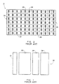
- FIG. 2 there is shown schematically the bar 21 of FIG. 1 that is constructed according to the prior art. It is to be understood that the bar 21 is representative of the bars 22, 24 and 28, as such are constructed according to the prior art.
- the bar 21 is comprised of a plurality of pixels, such as the pixels 32, 36 and 37.
- the various pixels are distributed as to form a leading edge 33 and a trailing edge 35 (both shown stippled for illustration purposes), and a central bar region indicated generally by the reference numeral 34 (shown without stippling).
- the reference numeral 34 shown without stippling. It will be noted, with reference to the prior art bar 21, that all of the pixels, in the leading edge 33, the trailing edge 35 and the central region 34 are formed by black ink, represented in each pixel by the letter B.
- FIG. 3 a bar code 40 that is constructed according to the present invention.
- the bar code 40 is comprised of four elongated parallel and rectangular bars 41, 42, 44 and 48 that are each of the same length but of different widths respectively.
- the value of an individual bar is represented by the width of the bar.
- the bar 41 is shown schematically.
- the bar is constructed according to the present invention and it is to be understood that it is representative of the bars 42, 44 and 48 of the bar code 40, as such is constructed according to the present invention.
- the bar 41 is comprised of a plurality of pixels, such as the pixels 52, and 57.
- the bar 41 includes a top tier, generally indicated by the reference numeral 54, leading and trailing edges, generally indicated by the reference numerals 53 and 55, respectively, and a bottom tier generally indicated by the reference numeral 56. It will be recognized by the stippling that the pixels shown in the top tier 54, the leading and trailing edges 53 and 55, respectively, and in the bottom tier 56, are comprised of pixels containing the black colorant (represented by the letter B).
- a central checkerboard bar region, indicated generally by the reference numeral 58, is disposed between the leading and trailing edges 53 and 55, respectively, and the top and bottom tiers 54 and 56, respectively.
- the bar 41 contains a plurality of pixels, such as the pixels 47, 47a and 47b that are comprised of a combination of colorant C, where C is a combination of cyan, magenta and yellow.
- composition of the bar 41 represents a novel technique for conservation and management of the cyan, magenta and yellow colorants by the use of the combination of colorants C in the central region pixels 47, 47a and 47b, for example. Because of the deposition of these colorants in the central bar region 58, spitting the colorants during printhead servicing is substantially eliminated while the black colorant is conserved. Moreover, since the need for wasteful printhead servicing during bar code printing is eliminated, throughput is improved. These advantages are realized without any compromise in bar quality since the leading and trailing edges 53 and 55, respectively, are capable of transmitting a clear signal to a bar code reader.
- the bar code 50 includes a bar 71.
- the bar 71 is constructed according to the present invention and it is to be understood that it may be regarded as representative of bars 72, 74 and 78 of the bar code 50, as such is constructed according to the present invention.
- the bar 71 is comprised of a plurality of pixels, such as the pixels 66 and 67 which, are shown as stippled and containing the letter B, indicative of the black colorant.
- the bar 71 includes leading and trailing edges 63 and 65, respectively, which define a central bar region indicated generally by the reference numeral 64.
- the bar 71 contains a plurality of pixels, such as the pixels 68a, 68b and 68c, each containing the letter C.
- the pixels 68a, 68b and 68c are comprised of colorants other than black. These colorants, typically are cyan, magenta and yellow.
- composition of the bar 71 represents a novel technique for conservation and management of the cyan, magenta and yellow colorants by using these colorants in the central region pixels such as the pixels 68a, 68b and 68c.
- the black colorant represented by the letter B
- the need for wasteful printhead servicing is eliminated and throughput is improved.
- these advantages are realized without any compromise in bar quality since the leading and trailing edges 63 and 65, respectively, are capable of transmitting a clear signal to a bar code reader.
Landscapes
- Engineering & Computer Science (AREA)
- Physics & Mathematics (AREA)
- General Physics & Mathematics (AREA)
- Theoretical Computer Science (AREA)
- Multimedia (AREA)
- Signal Processing (AREA)
- Printers Characterized By Their Purpose (AREA)
- Ink Jet (AREA)
- Record Information Processing For Printing (AREA)
Abstract
Description
- The present invention relates generally to ink-jet printing and, more particularly, to a technique for printing a bar code while conserving colorant during bar code printing operations.
- Modern printing devices utilize an ink ejecting printhead that is often mounted in a carriage that is moved back and forth across print media, such as paper for example. As the printhead moves across the print media, a control system activates the printhead to deposit or eject ink droplets, or colorants, onto the print media to form images and text.
- The printhead is sometimes fluidly coupled to an ink container that supplies ink to the printhead. The container may be a multi-chamber ink container that contains more than one colorant. Such containers typically contain one or more of the following colorants: black, cyan, yellow and magenta. Each chamber of the multi-chamber ink container is fluidly coupled to the printhead.
- A shortcoming of the multi-chamber ink container is that when any of the ink chambers of the container is depleted of ink, the entire ink container must be replaced, since the printing device is no longer capable of full color printing. Of course, discarding the entire multi-chamber container prevents the remaining colorants from being used, thereby causing waste. Thus, colorant management and conservation are important considerations in ink-jet printing operations.
- A significant challenge to colorant management and conservation is presented in bar code printing. It is understood that a bar code is a code consisting of ink lines of varying widths that can be read optically with a scanning device to convert data represented by the bar code into digital signals. In many cases the bar codes are printed in monochrome and black is the colorant of choice.
- Since modern ink-jet printers are equipped with printheads or containers having the four above-mentioned colorants, conventional methods of printing bar codes present shortcomings in both colorant management and conservation. In such cases, the printhead for black is actively utilized while the other printheads are relatively dormant. This is not a satisfactory condition because, in order to prevent the colorant from drying in the cyan, yellow and magenta printheads, it becomes necessary to interrupt a print process that usually entails spitting cyan, magenta and yellow colorant droplets into a spittoon during the print cycle. Each such spitting event entails waste of colorant inks. Nevertheless, in order to prevent loss of an entire printhead through the drying effect, conventional systems settle for less waste through the servicing technique.
- Not only is the interruption of the print cycle to service the printheads wasteful, printhead servicing during the print cycle slows throughput. In addition, such servicing may effect adversely print quality. In summary, printhead servicing during bar code printing is a wasteful practice that reduces throughput and tends to diminish print quality.
- From the foregoing it will be apparent that there is a need for a technique for printing bar codes wherein colorant waste is reduced. Desirably such a technique would afford improved throughput while affording good print quality.
- The various bars of a bar code convey information according to the width of the individual bars. In this regard, in order for a bar code reader to operate, the reader must be able to "read" the widths of the individual bars. If each bar of the code is regarded as having a leading edge and a trailing edge, each parallel to the long axis of the bar, the bar code reader can read a bar by measuring the distance between the leading edge and the trailing edge.
- According to the present invention, there is provided a technique of forming a bar of a bar code on print media by a printing device having a plurality of colorants. Each one of the individual bars has a leading edge and a trailing edge that help to define a central region of the bar. The relative locations of the leading edge and trailing edge are determined and a first colorant, usually black, is deposited at the leading edge. A composite of the first colorant, and the other printhead colorants, are deposited in the central region while the first colorant is deposited at the trailing edge. A bar of a bar code produced by this technique has a clearly defined leading and trailing edge for bar code readers to measure while the central region of the bar includes a composite of colorants.
- The technique of the present invention, and the bar code bar produced by the process, afford several advantages. While the leading and trailing edges enable efficient bar code readings, the central region of the bar serves to receive a composite of the colorants. In this manner, the black colorant is conserved since it no longer necessary for it to fill the entire bar and the firing duty cycle for the black printhead is reduced by about 25%. The other colorants are conserved since the need for servicing the printhead by spitting ink at a service station is eliminated. As a result, throughput and print quality are enhanced because servicing trips to the service station are eliminated as composites of colorants are deposited in the central region of the bar rather than spitting ink at the service station.
- In addition, the use of composite black colorant in the middle of the bar code does not impact scannability since the process is not random, on the fly spitting but is, instead, a directed process. Moreover, since the frequency of printhead nozzle servicing is reduced, throughput is increased. The novel technique of the present invention is applicable to any image or symbol intended to be scanned by a laser or optical scanner. It is especially useful in modern tag and label printers utilizing 1 inch swath printheads at 1-pass printing.
- While the invention discussed herein relates to a technique for printing bar codes, it will be apparent to those skilled in the art that the technique is suitable also for any image or symbol that is intended to be printed or scanned with a laser or optical scanner.
- Other aspects and advantages of the present invention will become apparent from the following detailed description, taken in conjunction with the accompanying drawings, illustrating by way of example the principles of the invention.
- FIG. 1 is a schematic view of a prior art bar code comprised of four bars;
- FIG. 2 is a schematic view of a portion of the bar code shown in FIG. 1 as such portion occurs in the prior art;
- FIG. 3 is a schematic view of a portion of a bar code that is constructed according to the present invention;
- FIG. 4 is a schematic view of a portion of the bar code of FIG. 3;
- FIG. 5 is a schematic view of another bar code which is constructed in accordance with the present invention; and
- FIG. 6 is a schematic view of a portion of the bar code of FIG. 5.
-
- As an aid to understanding the present invention, it will be helpful to consider first the construction of a bar code. In general, the bar code is comprised of monochromatic, often black, parallel bars. The information encoded in the bar code is conveyed to a reader by means of the varying widths of the individual bars. While the bars vary in width, the code itself is comprised of a plurality of parallel rectangles of generally uniform length.
- According to the present invention, each individual bar is regarded as having a leading edge and a trailing edge. These edges are spaced apart and parallel to the long axis of the bar. A bar code reader measures the distance between the edges in order to determine the value represented by the bar. As a result, it is important for the edges to be clearly defined and black is often the colorant of choice for such definition.
- The central region of the bar, arbitrarily defined as a region disposed between the leading edge and the trailing edge, is not as critical to the determination of bar value as the edges. Therefore, the deposition of black and other colorants in the central region of the bar will not impair the width measuring function of bar code readers. Such deposition, of course, eliminates trips to the spittoon for servicing and conserves both the black and other colorants.
- Referring now to FIG. 1 of the drawings, there is shown a schematic view of a prior
art bar code 20 that is comprised of four elongated parallel andrectangular bars bars - In FIG. 2 there is shown schematically the
bar 21 of FIG. 1 that is constructed according to the prior art. It is to be understood that thebar 21 is representative of thebars - The
bar 21 is comprised of a plurality of pixels, such as thepixels leading edge 33 and a trailing edge 35 (both shown stippled for illustration purposes), and a central bar region indicated generally by the reference numeral 34 (shown without stippling). It will be noted, with reference to theprior art bar 21, that all of the pixels, in the leadingedge 33, the trailingedge 35 and thecentral region 34 are formed by black ink, represented in each pixel by the letter B. - Since all of the pixels of the
bar 21 are black, the construction of the bar by a conventional printer having a plurality of colorants entails numerous trips to a spittoon during the printing process. As stated above, such printhead servicing is necessary in order to prevent drying of colorant in the printheads containing the non-black colorants. This technique is wasteful and it slows throughput. In addition, it is recognized that the interruption of a print job for printhead servicing can adversely affect print quality. - In contrast to the prior art bar, there is schematically shown in FIG. 3 a
bar code 40 that is constructed according to the present invention. Thebar code 40 is comprised of four elongated parallel andrectangular bars - In FIG. 4, the
bar 41 is shown schematically. The bar is constructed according to the present invention and it is to be understood that it is representative of thebars bar code 40, as such is constructed according to the present invention. - The
bar 41 is comprised of a plurality of pixels, such as thepixels bar 41 includes a top tier, generally indicated by thereference numeral 54, leading and trailing edges, generally indicated by thereference numerals reference numeral 56. It will be recognized by the stippling that the pixels shown in thetop tier 54, the leading and trailingedges bottom tier 56, are comprised of pixels containing the black colorant (represented by the letter B). A central checkerboard bar region, indicated generally by thereference numeral 58, is disposed between the leading and trailingedges bottom tiers prior art bar 21, thebar 41 contains a plurality of pixels, such as thepixels - It will be readily appreciated by those skilled in the art that the composition of the
bar 41 represents a novel technique for conservation and management of the cyan, magenta and yellow colorants by the use of the combination of colorants C in thecentral region pixels central bar region 58, spitting the colorants during printhead servicing is substantially eliminated while the black colorant is conserved. Moreover, since the need for wasteful printhead servicing during bar code printing is eliminated, throughput is improved. These advantages are realized without any compromise in bar quality since the leading and trailingedges - Referring now to FIGS. 5 and 6, there is shown schematically a
bar code 50 that is another embodiment of the present invention. Thebar code 50 includes abar 71. Thebar 71 is constructed according to the present invention and it is to be understood that it may be regarded as representative ofbars bar code 50, as such is constructed according to the present invention. - The
bar 71 is comprised of a plurality of pixels, such as thepixels bar 71 includes leading and trailingedges reference numeral 64. Once again, it will be noted that, unlike theprior art bar 21, thebar 71 contains a plurality of pixels, such as thepixels C. The pixels - It will be readily appreciated by those skilled in the art that the composition of the
bar 71 represents a novel technique for conservation and management of the cyan, magenta and yellow colorants by using these colorants in the central region pixels such as thepixels pixels edges - The present invention may be embodied in other specific forms without departing from its essential characteristics. The described embodiments are to be considered in all respects only as illustrative and not restrictive. The scope of the invention is, therefore, indicated by the appended claims rather than by the foregoing description. All changes that come within the meaning and range of equivalency of the claims are to be embraced within their scope.
- It will be evident that there are additional embodiments arid applications which are not disclosed in the detailed description but which clearly fall within the scope of the present invention. The specification is, therefore, intended not to be limiting, and the scope of the invention is to be limited only by the following claims.
Claims (10)
- A method of forming a bar (41) of a bar code (40) on print media by a printing device having a plurality of colorants, the bar (41) having a leading edge (53) and a trailing edge (55), the method comprising:
determining the location on the print media of the leading edge (53) of said bar (41):depositing a first colorant at said location;determining the location on the print media of the trailing edge (55) of said bar (41);depositing a composite of said first colorant and a second colorant between said leading edge (53) location and said trailing edge (55) location; anddepositing said first colorant at said trailing edge (55) location. - The method according to claim 1, wherein said first colorant depositing step at said trailing edge (55) location includes depositing a black colorant.
- The method according to claim 1, wherein said step of depositing a composite of said first colorant includes depositing a black colorant.
- The method according to claim 1, wherein said step of depositing a composite of said first colorant and a second colorant includes selecting colorants from the group of black, cyan, magenta and yellow.
- The method according to claim 1, wherein said step of depositing a composite of said first colorant and a second colorant includes selecting black colorant as said first colorant and selecting a composite of cyan, magenta and yellow as said second colorant.
- A bar code (58) having a plurality of bars (41), each one of said bars (41) comprising:a leading edge (53) having a first colorant deposited thereon;a trailing edge (55) having said first colorant deposited thereon; anda center region (54) having a composite of said first colorant and a second colorant deposited thereon.
- A method of forming a bar code (50), comprising:
depositing a plurality of ink droplets onto a media sheet to form a plurality of bars (71) indicative of the bar code (50), wherein each individual bar includes a border of a plurality of black ink droplets surrounding a checkerboard pattern of combination color ink droplets and black ink droplets. - The method of forming a bar code (50) according to claim 7, wherein each one of the combination of color ink droplets includes a combination of magenta, cyan and yellow ink droplets to form a black pixel.
- A method of forming a bar code (50), comprising:
depositing a plurality of ink droplets onto a media sheet to form a plurality of bars (71) indicative of the bar code (50), wherein each individual bar (71) includes alternating column patterns of a column of black ink droplets and a column of combination of color ink droplets. - The method of forming a bar code (50) according to claim 9, wherein each one of the combination of color ink droplets includes a combination of magenta, cyan and yellow ink droplets to form a black pixel.
Applications Claiming Priority (2)
| Application Number | Priority Date | Filing Date | Title |
|---|---|---|---|
| US09/505,752 US6439688B1 (en) | 1999-04-30 | 2000-02-16 | Technique for printing a bar code while conserving colorant |
| US505752 | 2000-02-16 |
Publications (1)
| Publication Number | Publication Date |
|---|---|
| EP1126694A1 true EP1126694A1 (en) | 2001-08-22 |
Family
ID=24011682
Family Applications (1)
| Application Number | Title | Priority Date | Filing Date |
|---|---|---|---|
| EP01301339A Withdrawn EP1126694A1 (en) | 2000-02-16 | 2001-02-15 | Bar code printing |
Country Status (3)
| Country | Link |
|---|---|
| US (1) | US6439688B1 (en) |
| EP (1) | EP1126694A1 (en) |
| JP (1) | JP2001260343A (en) |
Cited By (1)
| Publication number | Priority date | Publication date | Assignee | Title |
|---|---|---|---|---|
| EP1291187A1 (en) * | 2001-09-07 | 2003-03-12 | Hewlett-Packard Company | Optimized ink jet printing of barcodes |
Families Citing this family (9)
| Publication number | Priority date | Publication date | Assignee | Title |
|---|---|---|---|---|
| KR100592382B1 (en) * | 2003-10-13 | 2006-06-22 | 엘지전자 주식회사 | Barcode Marking Method of Electroluminescent Display Device |
| US20090020617A1 (en) * | 2003-10-13 | 2009-01-22 | Lg Electronics Inc. | Barcode marking method and apparatus for electro-luminescence display device |
| US8081304B2 (en) | 2006-07-31 | 2011-12-20 | Visualant, Inc. | Method, apparatus, and article to facilitate evaluation of objects using electromagnetic energy |
| US20100054287A1 (en) * | 2008-09-04 | 2010-03-04 | Farzan Ghauri | Method and System for Laser-Based High-Speed Digital Marking of Objects |
| WO2013119824A1 (en) * | 2012-02-10 | 2013-08-15 | Visualant, Inc. | Systems, methods and articles related to machine-readable indicia and symbols |
| US9316581B2 (en) | 2013-02-04 | 2016-04-19 | Visualant, Inc. | Method, apparatus, and article to facilitate evaluation of substances using electromagnetic energy |
| US9041920B2 (en) | 2013-02-21 | 2015-05-26 | Visualant, Inc. | Device for evaluation of fluids using electromagnetic energy |
| WO2014165003A1 (en) | 2013-03-12 | 2014-10-09 | Visualant, Inc. | Systems and methods for fluid analysis using electromagnetic energy |
| JP2021008051A (en) * | 2019-06-28 | 2021-01-28 | セイコーエプソン株式会社 | Recording device and recording method |
Citations (6)
| Publication number | Priority date | Publication date | Assignee | Title |
|---|---|---|---|---|
| EP0595650A2 (en) * | 1992-10-30 | 1994-05-04 | Canon Kabushiki Kaisha | Colour ink jet recording method and apparatus |
| US5418574A (en) * | 1992-10-12 | 1995-05-23 | Matsushita Electric Industrial Co., Ltd. | Video signal correction apparatus which detects leading and trailing edges to define boundaries between colors and corrects for bleeding |
| EP0739127A2 (en) * | 1995-04-21 | 1996-10-23 | Canon Kabushiki Kaisha | Method and apparatus for processing images |
| JPH09216388A (en) * | 1996-02-14 | 1997-08-19 | Seiko Epson Corp | Inkjet color recording device |
| EP0828228A2 (en) * | 1996-09-05 | 1998-03-11 | Canon Aptex Kabushiki Kaisha | Image forming apparatus and method |
| US5777758A (en) * | 1992-03-31 | 1998-07-07 | Canon Kabushiki Kaisha | Image processing apparatus and method for expanding color images based on block pixel and edge detection |
Family Cites Families (18)
| Publication number | Priority date | Publication date | Assignee | Title |
|---|---|---|---|---|
| US4222557A (en) | 1978-05-16 | 1980-09-16 | Wang Laboratories, Inc. | Printer feeding and stacking |
| JPH0425344Y2 (en) | 1984-10-27 | 1992-06-17 | ||
| US4890825A (en) | 1988-01-15 | 1990-01-02 | Emf Corporation | Paper sheet stacking and jogging apparatus |
| EP0580182B1 (en) | 1989-05-08 | 1998-08-12 | Mitsubishi Denki Kabushiki Kaisha | Printer |
| JP2945781B2 (en) | 1991-05-17 | 1999-09-06 | 株式会社リコー | Inkjet printer |
| US5479199A (en) | 1992-05-01 | 1995-12-26 | Hewlett-Packard Company | Print area radiant heater for ink-jet printer |
| JP3227284B2 (en) * | 1992-10-30 | 2001-11-12 | キヤノン株式会社 | Ink jet recording method and ink jet recording head |
| US5663750A (en) | 1994-04-05 | 1997-09-02 | Brother Kogyo Kabushiki Kaisha | Ink ejection device with ink saving mode used when remaining ink amount is small |
| DE69519704T2 (en) * | 1994-08-19 | 2001-04-26 | Fuji Xerox Co., Ltd. | Ink jet recording method and device using the same |
| IT1284844B1 (en) * | 1994-09-16 | 1998-05-22 | Seiko Epson Corp | COLOR INK JET PRINTING PROCEDURE |
| US5581284A (en) * | 1994-11-25 | 1996-12-03 | Xerox Corporation | Method of extending the life of a printbar of a color ink jet printer |
| US5812156A (en) | 1997-01-21 | 1998-09-22 | Hewlett-Packard Company | Apparatus controlled by data from consumable parts with incorporated memory devices |
| JP3320292B2 (en) * | 1995-02-13 | 2002-09-03 | キヤノン株式会社 | INK JET PRINTING APPARATUS AND INK JET PRINTING METHOD |
| US5883655A (en) | 1996-09-09 | 1999-03-16 | Xerox Corporation | Copy sheet stacking apparatus with articulated exit guide ramp |
| US5921406A (en) | 1997-02-14 | 1999-07-13 | Leone; Patrick | Passive paper stacker |
| US5870077A (en) | 1997-02-26 | 1999-02-09 | Hewlett-Packard Company | Method for tristimulus color data non-linear storage, retrieval, and interpolation |
| JPH115664A (en) | 1997-04-17 | 1999-01-12 | Canon Inc | Paper ejection stack device and image forming apparatus provided with the same |
| US6270187B1 (en) * | 1998-12-14 | 2001-08-07 | Hewlett-Packard Company | Method and apparatus for hiding errors in single-pass incremental printing |
-
2000
- 2000-02-16 US US09/505,752 patent/US6439688B1/en not_active Expired - Fee Related
-
2001
- 2001-02-15 EP EP01301339A patent/EP1126694A1/en not_active Withdrawn
- 2001-02-16 JP JP2001039327A patent/JP2001260343A/en active Pending
Patent Citations (6)
| Publication number | Priority date | Publication date | Assignee | Title |
|---|---|---|---|---|
| US5777758A (en) * | 1992-03-31 | 1998-07-07 | Canon Kabushiki Kaisha | Image processing apparatus and method for expanding color images based on block pixel and edge detection |
| US5418574A (en) * | 1992-10-12 | 1995-05-23 | Matsushita Electric Industrial Co., Ltd. | Video signal correction apparatus which detects leading and trailing edges to define boundaries between colors and corrects for bleeding |
| EP0595650A2 (en) * | 1992-10-30 | 1994-05-04 | Canon Kabushiki Kaisha | Colour ink jet recording method and apparatus |
| EP0739127A2 (en) * | 1995-04-21 | 1996-10-23 | Canon Kabushiki Kaisha | Method and apparatus for processing images |
| JPH09216388A (en) * | 1996-02-14 | 1997-08-19 | Seiko Epson Corp | Inkjet color recording device |
| EP0828228A2 (en) * | 1996-09-05 | 1998-03-11 | Canon Aptex Kabushiki Kaisha | Image forming apparatus and method |
Non-Patent Citations (1)
| Title |
|---|
| PATENT ABSTRACTS OF JAPAN vol. 1997, no. 12 25 December 1997 (1997-12-25) * |
Cited By (2)
| Publication number | Priority date | Publication date | Assignee | Title |
|---|---|---|---|---|
| EP1291187A1 (en) * | 2001-09-07 | 2003-03-12 | Hewlett-Packard Company | Optimized ink jet printing of barcodes |
| US7311395B2 (en) | 2001-09-07 | 2007-12-25 | Hewlett-Packard Development Company, L.P. | Optimized ink jet printing of barcodes |
Also Published As
| Publication number | Publication date |
|---|---|
| JP2001260343A (en) | 2001-09-25 |
| US6439688B1 (en) | 2002-08-27 |
Similar Documents
| Publication | Publication Date | Title |
|---|---|---|
| CN100445094C (en) | Ink jet printing system | |
| CN102582255B (en) | Printing apparatus and adjustment pattern printing method | |
| US7278700B2 (en) | Printing apparatus and printing method | |
| EP1695832B1 (en) | Printing apparatus | |
| EP1384592A1 (en) | Inkjet printing method and inkjet printing apparatus with defective nozzle compensation | |
| JPH07205541A (en) | Color inkjet recording method | |
| EP1907211B1 (en) | Imaging method and inkjet recording apparatus | |
| US7290858B2 (en) | Ink jet printing method and ink jet printing apparatus | |
| US20040109035A1 (en) | Printing apparatus, computer-readable medium, and printing method | |
| EP1225757A2 (en) | Printing method and system | |
| US7740336B2 (en) | Array type multi-pass inkjet printer and operating method thereof | |
| US6439688B1 (en) | Technique for printing a bar code while conserving colorant | |
| EP1038688A1 (en) | Mixing overprinting and underprinting of inks in an inkjet printer to speed up the dry time of black ink without undersirable hue shifts | |
| US20100053246A1 (en) | Fluid ejecting apparatus and method of ejecting fluid | |
| JPH11115247A (en) | Method for serial recording, serial recorder, and printer driver | |
| JP2010162804A (en) | Image forming device | |
| US20110193905A1 (en) | Printing device | |
| CN101489020A (en) | Image processing for enhanced print quality around edges | |
| EP1955848A2 (en) | Inkjet Printer Method | |
| JP2001080065A (en) | Ink-jet image-forming apparatus | |
| JP4363009B2 (en) | Printing apparatus, printing method, and program | |
| JP5899886B2 (en) | Image forming apparatus, image forming apparatus control method, and control program | |
| US6561609B2 (en) | Multiple drop weight printing system | |
| JP2001180018A (en) | Ink jet recording method and apparatus for recording by reciprocal scanning | |
| JP7725291B2 (en) | Inkjet recording apparatus and inkjet recording method |
Legal Events
| Date | Code | Title | Description |
|---|---|---|---|
| PUAI | Public reference made under article 153(3) epc to a published international application that has entered the european phase |
Free format text: ORIGINAL CODE: 0009012 |
|
| AK | Designated contracting states |
Kind code of ref document: A1 Designated state(s): DE FR GB Kind code of ref document: A1 Designated state(s): AT BE CH CY DE DK ES FI FR GB GR IE IT LI LU MC NL PT SE TR |
|
| AX | Request for extension of the european patent |
Free format text: AL;LT;LV;MK;RO;SI |
|
| RIN1 | Information on inventor provided before grant (corrected) |
Inventor name: BRUCH, XAVIER Inventor name: VIVES, JOAN CARLES Inventor name: STEPHENS, RONALD D., JR. |
|
| 17P | Request for examination filed |
Effective date: 20011022 |
|
| AKX | Designation fees paid |
Free format text: DE FR GB |
|
| 17Q | First examination report despatched |
Effective date: 20050330 |
|
| STAA | Information on the status of an ep patent application or granted ep patent |
Free format text: STATUS: THE APPLICATION IS DEEMED TO BE WITHDRAWN |
|
| 18D | Application deemed to be withdrawn |
Effective date: 20051011 |