EP1126533A2 - Closed battery module - Google Patents
Closed battery module Download PDFInfo
- Publication number
- EP1126533A2 EP1126533A2 EP01102507A EP01102507A EP1126533A2 EP 1126533 A2 EP1126533 A2 EP 1126533A2 EP 01102507 A EP01102507 A EP 01102507A EP 01102507 A EP01102507 A EP 01102507A EP 1126533 A2 EP1126533 A2 EP 1126533A2
- Authority
- EP
- European Patent Office
- Prior art keywords
- container
- battery module
- module
- partitions
- wall
- Prior art date
- Legal status (The legal status is an assumption and is not a legal conclusion. Google has not performed a legal analysis and makes no representation as to the accuracy of the status listed.)
- Granted
Links
Images


Classifications
-
- H—ELECTRICITY
- H01—ELECTRIC ELEMENTS
- H01M—PROCESSES OR MEANS, e.g. BATTERIES, FOR THE DIRECT CONVERSION OF CHEMICAL ENERGY INTO ELECTRICAL ENERGY
- H01M50/00—Constructional details or processes of manufacture of the non-active parts of electrochemical cells other than fuel cells, e.g. hybrid cells
- H01M50/20—Mountings; Secondary casings or frames; Racks, modules or packs; Suspension devices; Shock absorbers; Transport or carrying devices; Holders
-
- H—ELECTRICITY
- H01—ELECTRIC ELEMENTS
- H01M—PROCESSES OR MEANS, e.g. BATTERIES, FOR THE DIRECT CONVERSION OF CHEMICAL ENERGY INTO ELECTRICAL ENERGY
- H01M50/00—Constructional details or processes of manufacture of the non-active parts of electrochemical cells other than fuel cells, e.g. hybrid cells
- H01M50/10—Primary casings; Jackets or wrappings
- H01M50/102—Primary casings; Jackets or wrappings characterised by their shape or physical structure
- H01M50/112—Monobloc comprising multiple compartments
-
- H—ELECTRICITY
- H01—ELECTRIC ELEMENTS
- H01M—PROCESSES OR MEANS, e.g. BATTERIES, FOR THE DIRECT CONVERSION OF CHEMICAL ENERGY INTO ELECTRICAL ENERGY
- H01M2200/00—Safety devices for primary or secondary batteries
- H01M2200/20—Pressure-sensitive devices
-
- Y—GENERAL TAGGING OF NEW TECHNOLOGICAL DEVELOPMENTS; GENERAL TAGGING OF CROSS-SECTIONAL TECHNOLOGIES SPANNING OVER SEVERAL SECTIONS OF THE IPC; TECHNICAL SUBJECTS COVERED BY FORMER USPC CROSS-REFERENCE ART COLLECTIONS [XRACs] AND DIGESTS
- Y02—TECHNOLOGIES OR APPLICATIONS FOR MITIGATION OR ADAPTATION AGAINST CLIMATE CHANGE
- Y02E—REDUCTION OF GREENHOUSE GAS [GHG] EMISSIONS, RELATED TO ENERGY GENERATION, TRANSMISSION OR DISTRIBUTION
- Y02E60/00—Enabling technologies; Technologies with a potential or indirect contribution to GHG emissions mitigation
- Y02E60/10—Energy storage using batteries
Definitions
- the invention relates to a structure of a closed secondary battery module.
- Closed type secondary batteries are widely used as power supplies of various appliances because batteries do not allow leakage of an electrolytic solution, even if they are tilted, and can be used in any placement posture, such as dry batteries. Also widely used are battery modules integrally formed by connecting a plurality of closed secondary batteries so as to meet the power requirements of various appliances.
- Such a battery module has a structure in which an internal space of a closed container is divided into a plurality of small cells. Each cell contains an electrolytic solution, a positive electrode plate, and the like. Each cell forms a small secondary battery. The cells are electrically connected in series or parallel.
- the battery module is provided with a positive terminal and a negative terminal for extracting power.
- a typical secondary battery experiences a battery internal pressure increase due to generation of a gas at an electrode plate depending on the condition of use or the charging/discharging condition of the battery.
- the closed container receives external force due to, for example, some interference with the battery module. Taking such cases into consideration, an outer wall of the battery module is provided with such a strength that the outer wall will not easily break despite such a load.
- the closed battery module of the invention includes a partition dividing an internal space of a closed container into a plurality of cells, a unit cell formed in each of the cells divided by the partition, and a deformable portion provided in the partition.
- the deformable portion deforms before a stress greater than a predetermined allowable value occurs in an outer wall of the container by a load applied to the container.
- the stress greater than the predetermined allowable value may be a stress that does not immediately form a crack in an outer wall but that forms a crack when applied repeatedly. If the stress occurring in the outer walls can be controlled to or below the allowable value, it is possible to prevent cracks or the like that might otherwise be formed in the outer walls.
- FIG. 1 is a function block diagram illustrating a battery module applied to a hybrid vehicle in accordance with an embodiment of the present invention.
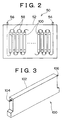
- FIG. 2 is a conceptual diagram illustrating a structure of a battery unit formed by using battery modules in accordance with an embodiment of the present invention.
- FIG. 3 is a diagram exemplifying an external configuration of a battery module in accordance with an embodiment of the present invention.
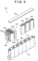
- FIG. 4 is an exploded assembly diagram illustrating a structure of a battery module in accordance with an embodiment of the invention.
- FIG. 5 is a diagram illustrating a configuration of partitions of a battery module in accordance with a first embodiment of the present invention.
- FIG. 6 is a diagram illustrating a configuration of partitions of a battery module for comparison with the first embodiment.
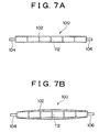
- FIGS. 7A and 7B are diagrams illustrating a state where the module internal pressure of the battery module abnormally increases in accordance with the first embodiment.
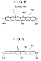
- FIG. 8 is a diagram illustrating a state where the module internal pressure of a battery module abnormally increases in accordance with a related art.
- FIG. 9 is a diagram illustrating a state where a module container of the battery module of the first embodiment receives a outside load.
- FIG. 10 is a diagram illustrating a state where a module container of a battery module in accordance with a related art receives a outside load.
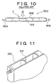
- FIG. 11 is a diagram showing a modification the partition configuration of the battery module in accordance with the first embodiment.
- FIG. 12 is a diagram illustrating a partition configuration of a battery module in accordance with a second embodiment of the present invention.
- FIG. 13 is a diagram illustrating a state where the module internal pressure of the battery module abnormally increases in accordance with the second embodiment.
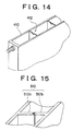
- FIG. 14 is a diagram illustrating a modification of the partition configuration of the battery module in accordance with the second embodiment.
- FIG. 15 is a diagram illustrating a partition configuration of a battery module in accordance with a third embodiment of the present invention.
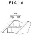
- FIG. 16 is a diagram illustrating a partition configuration of a battery module in accordance with the third embodiment of the present invention.
- FIG. 1 is a diagram illustrating a construction of a hybrid vehicle equipped with a closed battery module in accordance with a first embodiment of the present invention.
- the hybrid vehicle is a vehicle having an engine and an electric motor as drive power sources. As shown in FIG. 1, the hybrid vehicle has an engine 10, an electric motor 20, a torque converter 30, a drive circuit 40, a battery unit 50, a control unit 70, and a transmission 80.
- a closed battery module 100 of this embodiment is used as a component of battery unit 50.
- the engine 10 is an ordinary gasoline engine.
- An output shaft 12 of the engine 10 is connected to a rotor 22 of the motor 20.
- the motor 20 is a three-phase synchronous motor having the rotor 22 and a stator 24.
- a plurality of permanent magnets are provided on an outer peripheral surface of the rotor 22.
- Three-phase coils for creating rotating fields are wound between teeth provided on an inner peripheral surface of the stator 24.
- an alternating current is conducted through the three-phase coils of the stator 24.
- rotating fields are created. Due to the interaction between the rotating fields and the magnetic fields created by the permanent magnets of the rotor 22, the rotor 22 rotates.
- the drive power and rotating speed of the motor 20 can be controlled.
- the motor 20 also functions as an electric power generator.
- the drive circuit 40 is an inverter formed by using a semiconductor element.
- the drive circuit 40 has a switching function of connecting the terminals of the three-phase coils wound on the stator 24 and a direct-current supply of the battery unit 50 (described below).
- the control unit 70 Under a control by the control unit 70, the drive circuit 40 supplies current to each three-phase coil of the stator 24 while sequentially changing the voltage supplied to each coil, so that rotating fields are created.
- the motor 20 is driven.
- the rotor 22 is rotated by external force, AC electromotive forces caused in the three-phase coils are converted into DC electromotive forces by the drive circuit 40 sequentially changing the connection between each terminal of the three-phase coils and the battery unit 50.
- electric power can be stored into the battery unit 50.
- the battery unit 50 will be described below.
- the control unit 70 is a one-chip microcomputer having a CPU, a RAM, a ROM, and the like. By the CPU executing programs recorded in the ROM, the control unit 70 controls the engine 10, the drive circuit 40, or the like.
- the torque converter 30 is a drive power transmitting mechanism that utilizes a liquid.
- An input shaft 13 of the torque converter 30 is connected to the rotor 22 of the motor 20.
- the torque converter 30 is tightly closed.
- a transmission oil is contained in the torque converter 30 in a sealed manner.
- a turbine having a plurality of blades is provided at an end of each of the input shaft 13 and an output shaft 14 of the torque converter 30.
- the turbines are provided inside the torque converter 30 in such a manner that the input shaft 13-side turbine and the output shaft 14-side turbine face each other.
- the transmission 80 is a well-known automatic transmission formed by a planetary gear mechanism, a plurality of clutches,and the like.
- the transmission 80 is designed so that if the clutch engagement state is changed, the planetary gear unit changes the speed ratio between an input shaft and an output shaft 15 of the transmission 80.
- the operation of each clutch is controlled by the control unit 70.
- the output shaft 15 of the transmission 80 is connected to an axel 17 via a differential gear 16.
- the hybrid vehicle In the hybrid vehicle constructed as described above, drive power outputted from the engine 10 or the motor 20 is transmitted to the transmission 80 via the torque converter 30. After speed increase or speed reduction is caused by the transmission 80, drive power is transmitted to the axel 17, thereby driving the vehicle.
- the hybrid vehicle achieves improved energy efficiency as a whole.
- the motor 20 is caused to function as a generator to convert kinetic energy of the vehicle into electric energy, which is stored into the battery unit 50.
- the motor 20 covers a shortfall of the output of the engine 10.
- the energy efficiency of the whole hybrid vehicle may be improved.
- FIG. 2 is a conceptual diagram illustrating a structure of the battery unit 50.
- the battery unit 50 has a structure in which a plurality of closed type battery modules 100 are contained in a case 52.
- FIG. 3 illustrates an external configuration of a closed battery module 100.
- the closed battery module 100 of the embodiment has a configuration in which two terminals, that is, a positive electrode terminal 104 and a negative electrode terminal 106, protrude from a module container 102 that has a thin box-like shape.
- thirty-eight (38) closed battery modules 100 are contained in the case 52 of the battery unit 50.
- the closed battery modules 100 are connected to one another in series by electric wires 58, and are connected to a positive electrode-side output terminal 54 and a negative electrode-side output terminal 56 of the battery unit 50.
- the battery unit 50 having may have voltage and current values.
- Each closed battery module 100 generates Joule heat due to internal resistance during discharging or charging. Therefore, to allow dissipation of Joule heat, the battery modules are disposed at fixed intervals.
- FIG. 4 is a diagram illustrating a structure of the closed battery module 100.
- the closed battery module 100 has a structure in which a plurality of unit electric cells 120 are contained in a lower case 110, and are enclosed by an upper plate 116.
- An inner space of the lower case 110 is divided into a plurality of small cells. Each cell contains one unit electric cell 120.
- the lower case 110 is divided into six cells. A total of six unit electric cells 120 are contained in the cells.
- the lower case 110 is formed from a highly insulative resin material.
- Each unit electric cell 120 is formed by alternately stacking pairs of a positive electrode 122 and a separator 126, and pairs of a negative electrode 124 and a separator 126.
- the positive electrodes 122 are welded at one end side thereof to a positive electrode plate 128.
- the negative electrodes 124 are welded at one end side thereof to a negative electrode plate 129.
- the separators 126 are formed from a paper or a resin-made non-woven cloth having good gas permeability.
- a separator 126 is disposed between each pair of adjacent electrodes so as to prevent electric contact between the positive electrode 122 and the negative electrode 124.
- Each unit electric cell 120 of this embodiment is comprised of nickel-hydrogen secondary cell.
- the material of the positive electrodes 122 is a nickel-based alloy.
- the material of the negative electrodes 124 is a hydrogen storage alloy.
- As the electrolytic solution a strong alkali solution is used.
- the claimed embodiment is not limited to the nickel-hydrogen secondary batteries, but is applicable to any closed battery module.
- the positive electrode plate 128 and the negative electrode plate 129 of every two adjacent unit electric cells 120 are interconnected by an electrically conductive member 118, such as a conductive wire.
- an electrically conductive member 118 such as a conductive wire.
- Each one of partitions 112 separating the cells has in its upper portion a cutout for passing an electrically conductive member 118.
- the closed battery module 100 having the above-described structure prevents leakage of the electrolytic solution contained therein even if the module 100 is tilted.
- six nickel-hydrogen cells each producing an electromotive force of 1.2 V, are connected in series, and, therefore, one closed battery module 100 produces a power of 7.2 V.
- the closed battery module 100 When the closed battery module 100 discharges power, Joule heat is generated due to the internal resistance of the closed battery module 100. Joule heat is also generated due to the internal resistance when the closed battery module 100 is charged.
- the closed battery module 100 has a thin flat shape as shown in FIGS. 3 and 4, that is, has a large surface area relative to its volume. Therefore, Joule heat can be efficiently released.
- the electrolytic solution When a secondary battery is over-charged or over-discharged, the electrolytic solution is electrolyzed so that a gas is produced on an electrode.
- oxygen gas is produced from the positive electrode plate side during the over-charged state, and hydrogen gas is generated from the positive electrode plate side during the over-discharged state, so that the internal pressure on the closed battery module 100 temporarily rises.
- the lower case 110 and the upper plate 116 of the closed battery module 100 are formed with a strength that withstands such a pressure rise.
- FIG. 5 is an enlarged fragmentary view of the lower case 110 used in the closed battery module 100.
- each of the partitions 112 dividing the internal space of the lower case 110 has a folding screen-like shape is formed by bending a flat plate.
- FIG. 6 shows an enlarged view of a lower case 910 in which partitions and container outer walls have approximately equal thicknesses.
- FIG. 7A is a diagram showing a view of the lower case 110 as described above.
- broken lines indicate that the internal space of the module container 102 is divided into six cells by the partitions 112.
- each partition 112 has in its upper portion the cutout 114 for a connection between the electrode plates of the adjacent cells. Therefore, the internal pressure in the cells equally rises.
- the module container 102 is formed so as to withstand a predetermined internal pressure rise. Therefore, if the amount of pressure rise is small, the module container 102 does not significantly deform.
- FIG. 7B is a diagram illustrating a state where the internal pressure on the closed battery module 100 rises because of, for example, continuation of the over-charged state or the over-discharged state for a long time due to the driving condition of the vehicle.
- FIG. 8 illustrates a state where a rise occurs in the internal pressure on a battery module 900 provided with partitions 912 and container walls of approximately equal thicknesses. Because the partitions 912 and the container walls have approximately equal thicknesses, deformation of the walls is impeded. As a result, a module container 902 deforms into a shape where the module container is constricted at portions adjacent to the partitions 912. That is, even though opposite ends of each partition wall 912 having a flat plate shape receive such loads as to extend the partition, the walls formed from the same resin material as that of the lower case body do not substantially elongate. Therefore, the wall faces of the module container 902 are restrained at partition portions, and deform into a shape as shown in FIG. 8.
- the container walls of the module container 902 are restrained at the partition portions as mentioned above, the increase in the capacity is small and the reduction in the container internal pressure caused by deformation of the walls is small although the container wall faces expand outwards to some extent. Therefore, the container walls deform in such a manner that the container wall faces further expand outwards.
- the container walls deform in this manner, bending deformations occur in portions at and around junctions between the container walls and the partitions, and high stresses occur in these portions.
- stress concentration occurs at or around the junctions. If the stress locally occurring in the container walls exceeds an allowable stress of the lower case material, there is a danger of formation of a crack in the module container 902.
- the partitions 112 of the present invention have a shape as is formed by bending a flat plate as show in FIG. 5. Therefore, upon receiving a certain load in such a direction as to extend the partitions 112, the partitions 112 elongate. As a result, the module container 102 deforms into a shape where the container is expanded altogether without substantial constrictions at the partitions, as shown in FIG. 7B. As is apparent from comparison between FIG. 7B and FIG. 8, the walls of the module container do not have great bending deformation when the module container is in a shape as shown in FIG. 7B, that is, a shape where the container is expanded altogether without substantial constrictions at the partitions. Therefore, the module container 102 avoids the danger of formation of a crack or the like.
- the battery module 100 of the first embodiment is able to avoid an event that a crack or the like is formed in the module container 102, not only in the aforementioned case but also in other cases, such as the case where the closed battery module 100 receives an external load.
- FIG. 9 is a diagram illustrating a state where the module container 102 deforms when the battery module 100 interferes with an external member so that a wall surface of the module container 102 receives a outside load.
- FIG. 10 is a diagram illustrating a state where the battery module 900 having partitions that are approximately as thick as the container walls receives a outside load.
- a load acting from outside is indicated by an arrow B.
- the load acts on partitions 912 in such a direction as to compress the partitions from outside.
- the partitions formed from the same resin material as that of the lower case body, barely compress. Therefore, the wall of the module container 902 deforms so that a portion at and around the point of receiving the load becomes greatly dented.
- the wall receives, at a portion indicated by C in FIG. 10, a bending deformation. As a result, there is a danger of formation of a crack or the like in this portion of the module container 902.
- the partitions 112 in the claimed embodiment have a shape formed by bending a flat plate as shown in FIG. 5, so that with a certain load, the partitions 112 can become compressed. That is, upon receiving a load as indicated by an arrow B in FIG. 9, partitions 112 near the point of load deform in a contracting manner. As a result, a area of the wall of the module container 102 deforms as indicated in FIG. 9. Comparing FIG. 9 and FIG. 10, the container wall does not undergo a great deformation if the module container deforms as indicated in FIG. 9, and deforms so that a broad area of the container wall becomes dented. Therefore, formation of a crack or the like is less likely in the module container 102.
- partitions 112 have a shape as is formed by folding a flat plate and where when the module container receives an external force, partitions elastically deform so that folded portions bend.
- folded portions may plastically deform.
- partitions break at folded portions when the module container receives a predetermined external force. As partitions break at folded portions by a load, the stress occurring in a wall of the module container decreases. Therefore, formation of a crack or the like in the container walls can be avoided.
- the partitions 112 have a shape as is formed by folding a flat plate
- the partitions are not limited to the shape shown in FIG. 5, but may have any shape as long as the shape allows the partitions to deform in an expandable and contactable manner in accordance with the load from outside.
- partitions 212 having a curved shape as shown in FIG. 11 are also possible.
- the partitions may have a shape where curvature is partially provided. If a module container is formed by using a lower case 210 provided with the partitions 212 having the aforementioned shape, it is possible to avoid formation of a crack or the like in the container outer walls even if an external force acts on the module container.
- FIG. 12 is an enlarged fragmentary view of a lower case 310 used in a battery module 300 of the second embodiment.
- the battery module 300 of the second embodiment is applied to a hybrid system as indicated in FIG. 1.
- each of partitions 312 dividing an internal space of the lower case 310 has a central portion that is reduced in wall thickness.
- the battery module 300 of the second embodiment is provided with partitions having a configuration as shown in FIG. 12. This configuration makes it less likely that a crack will be formed in an outer wall of a module container 302 even when the internal pressure on the module container 302 abnormally rises.
- FIG. 13 is a diagram showing a view of the battery module 300 taken from above. When the battery module 300 enters an over-charged state or an over-discharged state, a gas is produced at a positive electrode plate, so that the internal pressure on the module container 302 increases. If the amount of pressure increase is small, the module container 302 of the second embodiment barely deforms.
- partitions 312 receive strong tensile loads. Because the partitions 312 are formed from the same material as that of the lower case 310, the partitions 312 barely elongate when receiving tensile load. Thus, the walls face of the lower case 310 are restrained by the partitions 312. That is, as the internal pressure on the battery module 300 increases, the outer walls of the module container 302 deform into a shape where portions of the outer walls adjacent to partitions are constricted as shown in FIG. 8.
- each partition 312 of the module container 302 of the second embodiment has a reduced-wall thickness portion. Therefore, when the container internal pressure further rises, the reduced-wall thickness portion of a partition 312 breaks before a crack is formed in a container wall face.
- FIG. 13 is a diagram illustrating a state where a partition 312 has broken at a portion indicated by an arrow B. When a partition 312 breaks as shown in FIG. 13, portions of the wall of the container adjacent to the broken partition are released from restraint, and are allowed to deform in such a manner as to expand outwards. Therefore, capacity increases, and the container internal pressure decreases. As a result, the value of stress occurring in the container wall faces decreases, thereby avoiding formation of a crack.
- the breakage of the partition 312 brings about a state where the electrolytic solution is allowed to flow back and forth between the adjacent cells.
- the adjacent cells function just like a single cell, so that the electromotive force generated by the battery module 300 as a whole decreases. That is, a battery module 300 having a broken partition can be detected by measuring the terminal voltage of the battery module 300.
- each partition 312 has a reduced-wall thickness portion
- the partitions do not need to have the configuration shown in FIG. 12.
- the partitions may have any configuration as long as the partitions are breakable before a crack is formed in the module container outer walls.
- partitions 412 which are made thinner as indicated in FIG. 14.
- each partition may be formed by combining two protrusion-like members as shown in FIG. 15 or 16. More specifically, as shown in FIG. 15, a protrusion 512a is provided on one of the walls of the module container, and another protrusion 512b is protruded from the opposite wall so as to face the protrusion 512a. The two protrusions 512a, and 512b form a partition 512. The two protrusions 512a,and 512b are placed in tight contact with each other so as to prevent the electrolytic solution from passing through a gap between the protrusions. It is also possible to form each partition as shown in FIG.
- a protrusion 612a is protruded from a wall of the module container, and another protrusion 612b is protruded from the opposite wall, and the partition 612 is formed by the two protrusions 612a,and 612b.
- the two protrusions 612a,and 612b are placed in tight contact with each other so as to prevent passage of the electrolytic solution via a gap between the protrusions.
- the cells are separated from one another by the partitions 512 or 612, each formed by two protrusion-like members while the internal pressure on the module container is not very high. Therefore, during such a state, the battery module is able to generate, between the two terminals, an electromotive force corresponding to the number of cells.
- the internal pressure on the module container rises to a certain level, the entire container wall faces deformation because the partitions 512 or the partitions 612 do not restrain the container walls. Thus, reduced stress occurs in the walls of the module container, so that there is no danger of formation of a crack or the like in the container wall.
- each partition 612 as shown in FIG. 16 is deformable in the compressing direction in response to load in such a direction as to contract the partition.
- the partitions 612 do not restrain the container wall a when load is applied from outside.
- the partitions 612 allow deformation of broad areas of the walls of the module container. Therefore, no great stress occurs locally in a wall of the module container, so that formation of a crack in the container can be avoided.
- the partitions (312) dividing the container (310) internal space restrict deformation of the container outer walls (302), so that great stress is likely to occur in the outer walls (302).
- the stress caused in the container outer walls (302) decreases, so that formation of a crack or the like in the container outer walls (302) becomes less likely.
Landscapes
- Chemical & Material Sciences (AREA)
- Chemical Kinetics & Catalysis (AREA)
- Electrochemistry (AREA)
- General Chemical & Material Sciences (AREA)
- Battery Mounting, Suspending (AREA)
- Sealing Battery Cases Or Jackets (AREA)
- Gas Exhaust Devices For Batteries (AREA)
Abstract

Description
Claims (7)
- A closed type battery module (100) wherein an internal space of a closed container (110) is divided into a plurality of cells by a partition (112), and a unit cell (120) is formed in each of the cells, characterized in that the partition (112) has a deformable portion that deforms before a stress greater than a predetermined allowable value occurs in an outer wall of the container (110) by a load applied to the container.
- A battery module (100) according to claim 1, wherein the unit cell (120) is a secondary battery.
- A battery module (100) according to claim 1, wherein the deformable portion is a member that is plastically deformable by the load.
- A battery module (100) according to claim 1, wherein the deformable portion a member that is elastically deformable by the load.
- A battery module (100) according to claim 1, wherein the deformable portion is a member whose strength is set so that the member breaks before the stress occurring in the outer wall of the container exceeds the predetermined allowable value.
- A battery module (100) according to any one of claims 1 to 5, characterized in that the predetermined allowable value of the stress corresponds to a stress that breaks the outer wall of the container.
- A battery module (100) according to any one of claims 1 to 5, characterized in that the stress caused in the outer wall of the container by the load is a stress caused adjacent to a junction between the partition and the outer wall of the container.
Applications Claiming Priority (2)
| Application Number | Priority Date | Filing Date | Title |
|---|---|---|---|
| JP2000036381 | 2000-02-15 | ||
| JP2000036381A JP3873563B2 (en) | 2000-02-15 | 2000-02-15 | Sealed battery module |
Publications (3)
| Publication Number | Publication Date |
|---|---|
| EP1126533A2 true EP1126533A2 (en) | 2001-08-22 |
| EP1126533A3 EP1126533A3 (en) | 2002-04-10 |
| EP1126533B1 EP1126533B1 (en) | 2008-09-03 |
Family
ID=18560428
Family Applications (1)
| Application Number | Title | Priority Date | Filing Date |
|---|---|---|---|
| EP01102507A Expired - Lifetime EP1126533B1 (en) | 2000-02-15 | 2001-02-05 | Closed battery module |
Country Status (6)
| Country | Link |
|---|---|
| US (1) | US6645668B2 (en) |
| EP (1) | EP1126533B1 (en) |
| JP (1) | JP3873563B2 (en) |
| KR (2) | KR100404440B1 (en) |
| CN (1) | CN1180492C (en) |
| DE (1) | DE60135593D1 (en) |
Cited By (4)
| Publication number | Priority date | Publication date | Assignee | Title |
|---|---|---|---|---|
| EP2793290A1 (en) * | 2013-04-17 | 2014-10-22 | Samsung SDI Co., Ltd. | Battery module |
| US10236518B2 (en) | 2008-06-12 | 2019-03-19 | 24M Technologies, Inc. | High energy density redox flow device |
| US10483582B2 (en) | 2012-12-13 | 2019-11-19 | 24M Technologies, Inc. | Semi-solid electrodes having high rate capability |
| US11909077B2 (en) | 2008-06-12 | 2024-02-20 | Massachusetts Institute Of Technology | High energy density redox flow device |
Families Citing this family (21)
| Publication number | Priority date | Publication date | Assignee | Title |
|---|---|---|---|---|
| CN100341192C (en) * | 2001-10-01 | 2007-10-03 | 松下电器产业株式会社 | Sealed alkaline battery |
| US20040247995A1 (en) * | 2003-06-09 | 2004-12-09 | Devitt John L. | Electrical storage battery |
| KR20060037598A (en) * | 2004-10-28 | 2006-05-03 | 삼성에스디아이 주식회사 | Battery module |
| US7989104B2 (en) | 2004-10-28 | 2011-08-02 | Samsung Sdi Co., Ltd. | Battery module |
| JP4720150B2 (en) * | 2004-11-12 | 2011-07-13 | 株式会社Gsユアサ | Assembled battery |
| KR100740126B1 (en) * | 2006-02-02 | 2007-07-16 | 삼성에스디아이 주식회사 | Partition wall for a secondary battery module and a secondary battery module including the same |
| JP5173167B2 (en) * | 2006-08-25 | 2013-03-27 | トヨタ自動車株式会社 | Power storage module |
| JP4999405B2 (en) * | 2006-09-04 | 2012-08-15 | ソニーモバイルコミュニケーションズ株式会社 | Battery pack |
| US8697275B2 (en) * | 2009-03-04 | 2014-04-15 | Samsung Sdi Co., Ltd. | Rechargeable battery having an extendable case region |
| JP5393365B2 (en) * | 2009-09-11 | 2014-01-22 | 日産自動車株式会社 | Battery module |
| WO2013129117A1 (en) * | 2012-02-29 | 2013-09-06 | 住友重機械工業株式会社 | Power shovel |
| DE102012210611A1 (en) * | 2012-06-22 | 2013-12-24 | Robert Bosch Gmbh | Energy storage unit with two separate electrochemical areas |
| JP5862608B2 (en) * | 2013-05-28 | 2016-02-16 | 株式会社デンソー | Battery assembly |
| US10115942B2 (en) * | 2013-06-05 | 2018-10-30 | The Regents Of The University Of California | Rate-sensitive and self-releasing battery cells and battery-cell structures as structural and/or energy-absorbing vehicle components |
| US9911951B2 (en) * | 2014-09-30 | 2018-03-06 | Johnson Controls Technology Company | Battery module compressed cell assembly |
| US9847531B2 (en) | 2015-12-01 | 2017-12-19 | Ut-Battelle, Llc | Current collectors for improved safety |
| EP3545576A1 (en) | 2016-11-28 | 2019-10-02 | QuantumScape Corporation | Pressurized electrochemical cell |
| CN109119562B (en) * | 2018-08-29 | 2021-09-28 | 义乌市坤玥玩具有限公司 | Lithium battery pack |
| KR20230040668A (en) * | 2021-09-16 | 2023-03-23 | 주식회사 엘지에너지솔루션 | Battery pack and device including the same |
| US20230100022A1 (en) * | 2021-09-28 | 2023-03-30 | Hyundai Mobis Co., Ltd. | Battery pack assembly |
| CN121355505A (en) * | 2025-12-19 | 2026-01-16 | 比亚迪股份有限公司 | Battery packs and electrical equipment |
Family Cites Families (13)
| Publication number | Priority date | Publication date | Assignee | Title |
|---|---|---|---|---|
| IT1045483B (en) * | 1974-11-19 | 1980-05-10 | Europ Accumulateurs | ASSEMBLY PROCEDURE FOR A BATTERY OF ACCUMULATORS AND BATTERY OBTAINED BY SUCH PROCEDURE |
| JPS55122372A (en) * | 1979-03-15 | 1980-09-20 | Shin Kobe Electric Mach Co Ltd | Production of storage battery |
| JPS5987756A (en) * | 1982-11-10 | 1984-05-21 | Yuasa Battery Co Ltd | Lead storage battery |
| JPH03240511A (en) * | 1990-02-19 | 1991-10-25 | Matsushita Electric Ind Co Ltd | Resin container |
| DE4028585C1 (en) * | 1990-09-08 | 1991-09-19 | Mercedes-Benz Aktiengesellschaft, 7000 Stuttgart, De | Battery housing of plastics material - has lines of weakness ensuring break up in defined sections upon internal explosion of developed gas |
| JPH07134973A (en) * | 1993-11-10 | 1995-05-23 | Japan Storage Battery Co Ltd | Sealed lead acid battery |
| KR950021520U (en) * | 1993-12-29 | 1995-07-28 | Battery case for electric vehicle | |
| JPH09134708A (en) * | 1995-11-13 | 1997-05-20 | Shin Kobe Electric Mach Co Ltd | Battery case |
| JPH09199090A (en) * | 1996-01-23 | 1997-07-31 | Japan Storage Battery Co Ltd | Storage battery |
| JPH10188927A (en) * | 1996-12-20 | 1998-07-21 | Toyo Takasago Kandenchi Kk | Assembly battery structure |
| JP3724103B2 (en) * | 1997-03-11 | 2005-12-07 | トヨタ自動車株式会社 | Battery assembly |
| JPH10334874A (en) | 1997-06-03 | 1998-12-18 | Japan Storage Battery Co Ltd | Monoblock storage battery |
| JPH11213962A (en) * | 1998-01-30 | 1999-08-06 | Yuasa Corp | Storage battery |
-
2000
- 2000-02-15 JP JP2000036381A patent/JP3873563B2/en not_active Expired - Lifetime
-
2001
- 2001-02-05 EP EP01102507A patent/EP1126533B1/en not_active Expired - Lifetime
- 2001-02-05 DE DE60135593T patent/DE60135593D1/en not_active Expired - Lifetime
- 2001-02-14 KR KR10-2001-0007218A patent/KR100404440B1/en not_active Expired - Lifetime
- 2001-02-15 CN CNB011046597A patent/CN1180492C/en not_active Expired - Lifetime
- 2001-02-15 US US09/783,039 patent/US6645668B2/en not_active Expired - Lifetime
-
2003
- 2003-08-20 KR KR10-2003-0057474A patent/KR20030072291A/en not_active Ceased
Cited By (8)
| Publication number | Priority date | Publication date | Assignee | Title |
|---|---|---|---|---|
| US10236518B2 (en) | 2008-06-12 | 2019-03-19 | 24M Technologies, Inc. | High energy density redox flow device |
| US11342567B2 (en) | 2008-06-12 | 2022-05-24 | Massachusetts Institute Of Technology | High energy density redox flow device |
| US11909077B2 (en) | 2008-06-12 | 2024-02-20 | Massachusetts Institute Of Technology | High energy density redox flow device |
| US10483582B2 (en) | 2012-12-13 | 2019-11-19 | 24M Technologies, Inc. | Semi-solid electrodes having high rate capability |
| US11018365B2 (en) | 2012-12-13 | 2021-05-25 | 24M Technologies, Inc. | Semi-solid electrodes having high rate capability |
| US11811119B2 (en) | 2012-12-13 | 2023-11-07 | 24M Technologies, Inc. | Semi-solid electrodes having high rate capability |
| EP2793290A1 (en) * | 2013-04-17 | 2014-10-22 | Samsung SDI Co., Ltd. | Battery module |
| US10381614B2 (en) | 2013-04-17 | 2019-08-13 | Samsung Sdi Co., Ltd. | Battery module |
Also Published As
| Publication number | Publication date |
|---|---|
| US6645668B2 (en) | 2003-11-11 |
| KR20030072291A (en) | 2003-09-13 |
| CN1310482A (en) | 2001-08-29 |
| KR100404440B1 (en) | 2003-11-03 |
| DE60135593D1 (en) | 2008-10-16 |
| CN1180492C (en) | 2004-12-15 |
| KR20010082622A (en) | 2001-08-30 |
| JP3873563B2 (en) | 2007-01-24 |
| EP1126533A3 (en) | 2002-04-10 |
| US20010014417A1 (en) | 2001-08-16 |
| JP2001229900A (en) | 2001-08-24 |
| EP1126533B1 (en) | 2008-09-03 |
Similar Documents
| Publication | Publication Date | Title |
|---|---|---|
| US6645668B2 (en) | Closed battery module | |
| KR100361881B1 (en) | Storage battery | |
| JP6686286B2 (en) | Prismatic secondary battery and assembled battery using the same | |
| JP5059990B2 (en) | Fixing method of assembled battery and secondary battery | |
| EP3428997B1 (en) | Battery pack | |
| EP1914817B1 (en) | Rechargeable battery and battery module using the same | |
| US20100200314A1 (en) | Energy storage assembly with poka-yoke connections | |
| US20100282529A1 (en) | Electrochemical cell and energy storage assembly | |
| JP2001110382A (en) | Sealed prismatic battery | |
| US20100273043A1 (en) | Electrochemical cell with weld points connections and energy storage assembly | |
| US7353894B2 (en) | Sealed nickel-metal hydride storage cells and hybrid electric having the storage cells | |
| EP4064447A1 (en) | Electricity storage device and insulating holder | |
| JP5047412B2 (en) | Assembled battery | |
| JP2001229896A (en) | Battery pack | |
| KR102924458B1 (en) | Battery, and battery pack and vehicle comprising the battery | |
| JP7806724B2 (en) | Power System | |
| JP7440455B2 (en) | Control method for alkaline secondary batteries | |
| JP7259719B2 (en) | battery system | |
| KR100578815B1 (en) | Secondary Battery and Cap Assembly Used Here | |
| CN121149626A (en) | Battery cell with pins for welding electrode tabs | |
| JP2024001754A (en) | Energy storage module | |
| EP4133354A1 (en) | Secondary battery pack, charger and discharger | |
| JP2003338308A (en) | Battery | |
| JPH0745258A (en) | Secondary battery jar |
Legal Events
| Date | Code | Title | Description |
|---|---|---|---|
| PUAI | Public reference made under article 153(3) epc to a published international application that has entered the european phase |
Free format text: ORIGINAL CODE: 0009012 |
|
| 17P | Request for examination filed |
Effective date: 20010205 |
|
| AK | Designated contracting states |
Kind code of ref document: A2 Designated state(s): DE FR GB Kind code of ref document: A2 Designated state(s): AT BE CH CY DE DK ES FI FR GB GR IE IT LI LU MC NL PT SE TR |
|
| AX | Request for extension of the european patent |
Free format text: AL;LT;LV;MK;RO;SI |
|
| PUAL | Search report despatched |
Free format text: ORIGINAL CODE: 0009013 |
|
| AK | Designated contracting states |
Kind code of ref document: A3 Designated state(s): AT BE CH CY DE DK ES FI FR GB GR IE IT LI LU MC NL PT SE TR |
|
| AX | Request for extension of the european patent |
Free format text: AL;LT;LV;MK;RO;SI |
|
| AKX | Designation fees paid |
Free format text: DE FR GB |
|
| 17Q | First examination report despatched |
Effective date: 20050203 |
|
| 17Q | First examination report despatched |
Effective date: 20050203 |
|
| GRAP | Despatch of communication of intention to grant a patent |
Free format text: ORIGINAL CODE: EPIDOSNIGR1 |
|
| GRAS | Grant fee paid |
Free format text: ORIGINAL CODE: EPIDOSNIGR3 |
|
| GRAA | (expected) grant |
Free format text: ORIGINAL CODE: 0009210 |
|
| AK | Designated contracting states |
Kind code of ref document: B1 Designated state(s): DE FR GB |
|
| REG | Reference to a national code |
Ref country code: GB Ref legal event code: FG4D |
|
| REF | Corresponds to: |
Ref document number: 60135593 Country of ref document: DE Date of ref document: 20081016 Kind code of ref document: P |
|
| PLBE | No opposition filed within time limit |
Free format text: ORIGINAL CODE: 0009261 |
|
| STAA | Information on the status of an ep patent application or granted ep patent |
Free format text: STATUS: NO OPPOSITION FILED WITHIN TIME LIMIT |
|
| 26N | No opposition filed |
Effective date: 20090604 |
|
| REG | Reference to a national code |
Ref country code: GB Ref legal event code: 746 Effective date: 20130923 |
|
| REG | Reference to a national code |
Ref country code: DE Ref legal event code: R084 Ref document number: 60135593 Country of ref document: DE Effective date: 20130919 |
|
| REG | Reference to a national code |
Ref country code: FR Ref legal event code: PLFP Year of fee payment: 16 |
|
| REG | Reference to a national code |
Ref country code: FR Ref legal event code: PLFP Year of fee payment: 17 |
|
| REG | Reference to a national code |
Ref country code: FR Ref legal event code: PLFP Year of fee payment: 18 |
|
| PGFP | Annual fee paid to national office [announced via postgrant information from national office to epo] |
Ref country code: DE Payment date: 20200121 Year of fee payment: 20 Ref country code: GB Payment date: 20200129 Year of fee payment: 20 |
|
| PGFP | Annual fee paid to national office [announced via postgrant information from national office to epo] |
Ref country code: FR Payment date: 20200113 Year of fee payment: 20 |
|
| REG | Reference to a national code |
Ref country code: DE Ref legal event code: R079 Ref document number: 60135593 Country of ref document: DE Free format text: PREVIOUS MAIN CLASS: H01M0002020000 Ipc: H01M0050100000 |
|
| REG | Reference to a national code |
Ref country code: DE Ref legal event code: R071 Ref document number: 60135593 Country of ref document: DE |
|
| REG | Reference to a national code |
Ref country code: GB Ref legal event code: PE20 Expiry date: 20210204 |
|
| PG25 | Lapsed in a contracting state [announced via postgrant information from national office to epo] |
Ref country code: GB Free format text: LAPSE BECAUSE OF EXPIRATION OF PROTECTION Effective date: 20210204 |