EP1126358B1 - Anti-intrusion device - Google Patents
Anti-intrusion device Download PDFInfo
- Publication number
- EP1126358B1 EP1126358B1 EP01410019A EP01410019A EP1126358B1 EP 1126358 B1 EP1126358 B1 EP 1126358B1 EP 01410019 A EP01410019 A EP 01410019A EP 01410019 A EP01410019 A EP 01410019A EP 1126358 B1 EP1126358 B1 EP 1126358B1
- Authority
- EP
- European Patent Office
- Prior art keywords
- intrusion
- conductive
- protected
- conductive circuit
- membrane
- Prior art date
- Legal status (The legal status is an assumption and is not a legal conclusion. Google has not performed a legal analysis and makes no representation as to the accuracy of the status listed.)
- Expired - Lifetime
Links
Images


Classifications
-
- G—PHYSICS
- G08—SIGNALLING
- G08B—SIGNALLING OR CALLING SYSTEMS; ORDER TELEGRAPHS; ALARM SYSTEMS
- G08B13/00—Burglar, theft or intruder alarms
- G08B13/02—Mechanical actuation
- G08B13/12—Mechanical actuation by the breaking or disturbance of stretched cords or wires
- G08B13/126—Mechanical actuation by the breaking or disturbance of stretched cords or wires for a housing, e.g. a box, a safe, or a room
- G08B13/128—Mechanical actuation by the breaking or disturbance of stretched cords or wires for a housing, e.g. a box, a safe, or a room the housing being an electronic circuit unit, e.g. memory or CPU chip
-
- G—PHYSICS
- G06—COMPUTING; CALCULATING OR COUNTING
- G06F—ELECTRIC DIGITAL DATA PROCESSING
- G06F21/00—Security arrangements for protecting computers, components thereof, programs or data against unauthorised activity
- G06F21/70—Protecting specific internal or peripheral components, in which the protection of a component leads to protection of the entire computer
- G06F21/86—Secure or tamper-resistant housings
- G06F21/87—Secure or tamper-resistant housings by means of encapsulation, e.g. for integrated circuits
-
- H—ELECTRICITY
- H05—ELECTRIC TECHNIQUES NOT OTHERWISE PROVIDED FOR
- H05K—PRINTED CIRCUITS; CASINGS OR CONSTRUCTIONAL DETAILS OF ELECTRIC APPARATUS; MANUFACTURE OF ASSEMBLAGES OF ELECTRICAL COMPONENTS
- H05K1/00—Printed circuits
- H05K1/02—Details
- H05K1/0275—Security details, e.g. tampering prevention or detection
Definitions
- the present invention relates to an anti-intrusion device intended to protect a surface by which it would be possible to access objects, for example electronic circuits, in order to prevent access to such objects or to information contained in said objects.
- Another disadvantage of the prior art is its bulk. For use on small products, is forced to reduce the thickness of the walls but an intrusion by peeling (also called delamination), which consists of remove the material from the wall by thin layers, allows to reach the wire then to cross it without the deteriorate and therefore without being detected and continue to break through to the desired objects.
- peeling also called delamination
- Radiography systems may be sufficient to indicate the position of the conductor wire. Micro-openings can then allow to cross it by avoiding it and without being detected.
- Another disadvantage of the prior art is that it is unsuited to electronic devices having related parts with the outside world as connections, keyboards, displays ...
- the prior art is not suitable devices intended for the processing of smart cards, for make payment. These devices have the particularity of having many relationships with the outside world while requiring important security guarantees, both for the stored data in the device only for the data exchanged.
- a code identification code PIN code
- the display shows the entry of each data confidential by displaying an anonymous character, allowing thus to control from the outside the good progress of the procedure and to identify any malfunction of the keys of the keyboard.
- PIN code code identification code
- the display shows the entry of each data confidential by displaying an anonymous character, allowing thus to control from the outside the good progress of the procedure and to identify any malfunction of the keys of the keyboard.
- To guarantee the security of this input process identification in this scheme of operation it is necessary to protect at least the keyboard, the microprocessor, the display and the electrical circuits connecting these three elements.
- the prior art provides only a partial solution since it does not fully protect
- An object of the present invention is to provide a new device cheaper than those of the prior art for protect any surface or any volume containing objects from value or confidential data.
- Another object of the present invention is to provide a device particularly suitable for devices to seize confidential data including those with keyboards and billboards like payment terminals by map.
- Another object of the present invention is to provide a card processing device easily added to existing communication devices while guaranteeing the maximum security.
- Another object of the present invention is to provide a small device because a large number of devices are portable and that market orientation is miniaturization always more important.
- Another object of the present invention is to provide a device suitable for applications under conditions extremes, and in particular guaranteeing dust-tightness and the liquids of the devices on which it is used.
- the present invention provides a device anti-intrusion circuit comprising a conductive circuit placed on a surface to be protected and a means of measuring a characteristic associated with said driver circuit and able to react in cases of modifications of the said electrical characteristics, in wherein the conductive circuit is made of conductive ink.
- the driver circuit comprises a first conductive circuit element placed on the surface to be protected and a second element of conductive circuit placed above said first element and separated from it by an insulating layer provided with a bridge conductor electrically connecting the two circuit elements driver.
- the driver circuit is partly or wholly applied to a flexible membrane intended to be fixed to the surface to be protected.
- the anti-intrusion device comprises two flexible membranes in solidarity with each other, each containing an element of conductive circuit on one of their face, and comprising a bridge conductor to make an electrical connection between circuit elements of each of the two membranes.
- the anti-intrusion device is composed of several membranes flexible thin with conductive tracks silkscreened interconnected by conductive bridges made through said membranes so as to form the appearance of a unique flexible membrane, including a barrier three-dimensional anti-intrusion conductor.
- the anti-intrusion device is placed on an element to be protected, and includes contacts and an insulative tab securely attached to the element to be protected by one of its ends and whose other end can occupy two positions, the first interposed between said contacts and the second out of said contacts so as to form a switch adapted to detect the separation of said anti-intrusion device and said element protect.
- the measuring means of an electrical characteristic is placed at inside a volume at least partly protected by the circuit driver.
- the device includes a power supply placed at inside a volume at least partly protected by the circuit driver.
- the anti-intrusion device contains a component such as a switch, display or microprocessor between two membranes Flexible.
- the anti-intrusion device comprises an input means identification and display protected by a barrier protective conductor and connected to a means of managing the identity verification functions placed inside a protected volume.
- the anti-intrusion device is placed on a device, and the identification entry means is placed on the underside of said apparatus.
- the PIN entry device includes a system anti-intrusion of the aforementioned type and comprises a first membrane having a first anti-intrusion conductive track, a second membrane comprising a second conductive track anti-intrusion electrically connected to said first track anti-intrusion by a conductive bridge, a membrane keypad whose contacts are placed in a protected area between conductive anti-intrusion tracks.
- FIG. 1 represents an anti-intrusion device 1 the simplest possible according to the present invention. It represents a flexible membrane of the order of 0.1 mm thick compound mainly a Kapton, polycarbonate or polyurethane film of upper face 1.1 and whose lower face 1.2 has a screen printed track 2 made of conductive ink and characterized by some electrical resistance between his terminals 2a and 2b. This resistance is of the order of 0.08 Ohms per millimeter in length for tracks 0.5 mm wide and of standard thickness 0.008 mm.
- the anti-intrusion conductive track 2 is covered by an insulating varnish 3.
- the assembly represents an anti-intrusion membrane according to the invention which sticks on the surface of a device to protect.
- a logic device 5 makes it possible to verify, during permanent scans if there was no break in runway 2. Simply, it is planned to connect terminals 2a and 2b of the anti-intrusion system with two inputs of a microprocessor 5 which will detect any opening of the circuit 2. The device 5 will then use an algorithm allowing it to react to any intrusion detection by, for example, erasing confidential data or by triggering an alarm.
- the safety membrane being defined and placed around of a device or part of a device, it defines then within the device an area that is called protected since any intrusion will be detected.
- Element 5 being indispensable to management of the device, it is placed in this protected area as well as incidentally its power supply.
- Another advantage of the membrane described is its flexibility which allows to adapt it to a large number of forms of surfaces, even non-planar. It is of course possible to use a thicker and less flexible membrane or to apply the silkscreened track 2 directly on the inside of the shell of a device.
- Another advantage of the fineness of the membrane described is that it is possible to superimpose several of these membranes to increase the protection. It will then take one or more means 5 to monitor all tracks 2.
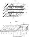
- FIGS 2a and 2b show a second embodiment an anti-intrusion device according to the invention.
- the device 1 consists of three membranes as described previously, A, B and C, glued with double adhesive films face (not shown) on each other. For ease of the representation, these membranes are exaggeratedly spaced on the figures.
- Each membrane has a conductive track 2 on its lower face. These tracks are interconnected by conductive inter-membrane bridges 6, made by means of holes through 4B and 4C through layers B and C and filled with conductive ink composed for example of particles silver taken in a polymer substrate; the whole form thus a conductive barrier in three dimensions. A break at any point this electrical barrier is detected by the device 5.
- the spacing between the different meshes conductive is chosen to minimize the intrusions.
- This device 1 will be applied to the device to be protected from the same way than previously.
- Figure 2a shows a first possible form of the conductive barrier which is a single and continuous track between terminals 2a and 2b occupying the three membranes A, B and C.
- This conductive track can only take two states, "Open” or “closed” between its two terminals, and it will be easy to know the state.
- Figure 2b shows a second possible form of the anti-intrusion conductive barrier. This forms a grid in three dimensions. Its electrical representation can to resemble a mounting of resistors in parallel. Thus, cuts in this grid will result in smaller variations in the case shown in Figure 2a that the person skilled in the art will know how to distinguish from other slight variations like those due to the temperature for example.
- Such a three-dimensional anti-intrusion device is advantageous because it makes the probability even lower of pass through the electrical barrier without being detected, even by cutting with a small tool. Moreover, he makes the intrusion by peeling impossible since it is impossible to peel more than one layer without cutting bridges 6 and be detected.
- FIG. 3 represents in section the combination of a keypad for entering confidential code as well as a display with a security device according to the present invention.
- Four membranes A, B, C and D are fixed on each other.
- the first membrane A comprises on its upper face a drawing 8 indicating the position of the keys on the keyboard. It includes a opening 10 located above the display 7.
- the membranes A, B and D include on their underside a screenprinted track 2 with conductive ink. 4B openings made in the membrane B allow to connect the anti-intrusion tracks 2 of each of the two membranes A and B using traversing bridges 6. For the sake of simplicity, the layers of glue and / or insulating varnish are not shown.
- Conductive tracks 2 of the membranes A and B will be placed above the contacts 9 described below so as to protect them.
- Membranes C and D respectively have on their lower faces and upper conductive elements 9 and spacers 11 so as to form electrical switches allowing to perform the function of keyboard keys according to a known technique, and described in particular in the patent application EP0727796.
- the membrane D also serves as a support for the display 7; it will eventually be covered by a window (not shown) inserted into the openings 10 of membranes A, B and C.
- the anti-intrusion conductive tracks 2 are arranged at immediate vicinity of these openings 10 to avoid any intrusion in this location.
- the conductive track 2 placed on the face lower diaphragm D is connected by conductive bridges 6, passing through conductive bridges 4C and 4D, to tracks 2 of upper membranes.
- the set of tracks 2 present on the lower faces of membranes A, B and D and bridges 6 forms a three-dimensional anti-intrusion conductive barrier, protecting the keyboard and display parts against attacks from all directions.
- This barrier possesses electrical characteristics that will be measured constantly from its terminals 2a and 2b by means 5 (not shown) as previously described.
- FIGS. An advantage of the invention, illustrated in FIGS. comes from the fact that it is possible to integrate within the multilayer structure, and therefore inside the intruder barrier electronic components such as a keyboard, switches, processors, displays ... This allows achieve low cost all kinds of electronic functions completely protected against intrusions from any direction.
- the use of flexible membranes of low Thickness allows easy integration into any device.
- FIG. 5 represents a device 20 for capturing identification code (PIN code) fully secured with the device of the invention as described in FIGS.
- the keyboard and the display are linked to microprocessor 5 by conductive circuits 12 and 13 (represented schematically) grouped in tablecloths and protected against frauds by leads 2 (not represented here by simplicity) until connected to the microprocessor 5.
- the connection of the web (comprising the connections 2a, 2b, 12 and 13) to the microprocessor 5 is embedded in the resin 14 to ensure its inaccessibility.
- This identification code entry device is completely secure since it includes a keyboard, a display and a microprocessor totally dedicated and protected against fraud.
- This device also has the advantages of being manufactured at low cost and represent a small footprint.
- FIG. 6 shows schematically, to facilitate explanation of the different functions, the implementation of a device 20 of the above type on a laptop 30, of to add a fully card payment feature secure.
- the laptop 30 has on its face superior 31 a keyboard 32 and a display 33. It can be worn with a removable handle 34 and communicates with the outside by a serial link with a suitable connector 35 allowing exchanges between its processor 36 and the outside. It is added a card reader, integrated in a compartment autonomous 37, watertight relative to the rest of the apparatus. the figure, a smart card 38 is inserted in the reading position through slot 39 of the card reader.
- a device 20 such as described in Figure 5 is glued on the underside 40 of the device, so as to present a second keyboard 8 and display 7 for entering the PIN code.
- the device 20, placed on the underside, is protected in the usual modes of use of the computer 30 by a removable cover 41.
- the apparatus 30 is turned over and rests on support points protuberances 42 provided on the usually upper face 31 when used as a payment terminal.
- the device 20 enters the compartment 37 through a opening 43 and the electrical connection layer, comprising the connections related to the operation of the keyboard, the display and anti-intrusion trellis, is connected to the inputs of the microprocessor 5 which will manage the payment function. This last is able to detect an intrusion through the device 20 and react to this intrusion.
- a second membrane anti-intrusion 1 as described in Figure 2a is used to protect the upper part of the device, at the compartment 37. It is fixed to the apparatus 30 by gluing on the surface 31.
- An additional diet (no shown) is placed in the protected area, in the resin 14, to make the anti-intrusion device autonomous and functional in case of neutralization of the main power supply of 30.
- an extra security measure it will be possible to provide a device as described in the patent application WO00 / 01100 to avoid the possibility of recovering data confidential from the external power supply of the microprocessor 5.
- One of the advantages of the device 20 according to the invention is its supple and fine membrane structure which facilitates its placement on all kinds of surface.
- the placement of the keyboard and the display for the payment on the back of the device avoids enlarging or cluttering the front surface; the virgin surface is exploited at best. This will in the sense of miniaturization of the devices.
- Another advantage of the device 20 comes from the fact it can be added to a device without compromising its seal, as illustrated in the previous example ( Figure 6).
- FIG. 7a shows the switch 44 in the case of a device in normal operating configuration.
- the device anti-intrusion 1 included between the hood 45 and the surface upper 31 of the device contains a tab 47 placed between two membranes A and B of the device 1, so as to isolate two contacts 48 placed opposite each membrane A and B.
- tongue 47 was attached to the hood 45 and the surface 31 by harpoons 49.
- this switch besides the fact that combines with the security device according to the invention, present many advantages: it is purely mechanical, it is open in normal operation, which avoids wear and tear the oxidation of the contacts for example, it is manufactured at low cost and it is not bulky.
- FIG. 8a shows a smart card 50 in perspective having an anti-intrusion device according to the invention.
- This device according to the invention as described above allows in particular to protect the connection between the chip (not shown) and contacts 51.
- an advantage of the invention is to be able to add to the smart card 50 new features totally secure against fraud as a 52 and a keyboard 53.
- the chip will perform the function of means of measurement. 5.
- a source of energy may be provided for the these new functions.
- Figure 8b shows a smart card incorporating a device according to the invention in section. Unlike the figure 8a, this is a contactless smart card, having a antenna 55. In order not to interfere with the antenna, the intrusion barrier 2 is only used on part of the card out of the antenna, so as to protect the chip 54, a display 7 and a keyboard 9. We can also imagine a keyboard in the antenna field, which would include means such as described in the application FR2736451 to avoid interference between the keyboard and the antenna.
- the safety device occupies all or part of the thickness and the surface a smart card. It is preferably implemented at the card manufacturing. However, it can also be added by the continuation on a classic card so as to cover the card to protect it. For conventional smart cards with contact, used as phone cards, it can be used to protect chip against intrusions to avoid many frauds which involves connecting unwanted chips to the chip initial, in the thickness of the map in an undetectable way to the naked eye.
- FIG. 9 represents a safe 60 incorporating a anti-intrusion device 1 according to the present invention. Its wall has a first thickness 61 steel then a second 62 in hard resin. In the latter is placed an envelope anti-intrusion 1 according to the present invention, covering the entire outer surface of the safe 60.
- the door 63 opens to using a PIN typed on a multilayer keypad protected by a device according to the invention such as that shown in Figure 3.
- a microprocessor 5, arranged inside the safe detects any intrusion through the membranes Anti-intrusion.
- the conductive tracks on the membranes have been performed on the lower faces thereof; they can the same on the upper faces. Only one membrane can have a conductive track 2 on each of its two faces, and have or not bridges 6 to connect these two tracks.
- the device can be made using layers very fine: 0.08 mm, or less if necessary. He can thus occupy a very small location and be very flexible. He can too be thicker if strength and rigidity are needed. It is possible to use various materials according to the report quality / price sought. For example, polyester films, polyurethane.
- the conductive ink used may be based on polymers containing conductive particles of metal (silver, gold) or carbon.
- Such circuits 2 can be made with substrates in Kapton with golden slopes. This last technology possesses, although more expensive excellent features electronic and mechanical.
- the security device can also base its detection deterioration of the tracks, on other electrical characteristics as resistance, for example capacity variations.
- Such a device can be combined with any input system identification, whether entering a PIN code as we have seen it but also the seizure of a biometric imprint, a optical or vocal input, etc.
Abstract
Description
La présente invention concerne un dispositif anti-intrusion destiné à protéger une surface par laquelle il serait possible d'accéder à des objets, par exemple des circuits électroniques, de façon à éviter que l'on ait accès auxdits objets ou à des informations contenues dans lesdits objets.The present invention relates to an anti-intrusion device intended to protect a surface by which it would be possible to access objects, for example electronic circuits, in order to prevent access to such objects or to information contained in said objects.
Les systèmes de sécurité actuels sont basés sur des matériaux durs, par exemple à base de nouvelles résines thermodurcissables de type polyester ou époxy, et de plaques d'aciers. On utilise en plus des fils métalliques conducteurs placés dans les parois à protéger et dont on mesure en permanence la résistance électrique de manière à pouvoir détecter une intrusion brutale entraínant la coupure de ces fils conducteurs.Current security systems are based on hard materials, for example based on new thermosetting resins polyester or epoxy type, and steel plates. In addition, conductive metal wires placed in the walls to be protected and whose resistance is permanently measured electrical so as to detect a sudden intrusion causing the cutting of these conductive wires.
Un inconvénient de cette solution de l'art antérieur, vient de son coût élevé.A disadvantage of this solution of the prior art, comes from its high cost.
Un autre inconvénient de l'art antérieur est son encombrement. Pour l'utiliser sur des produits de petite taille, on est contraint de réduire l'épaisseur des parois mais une intrusion par pelage (on dit aussi par délaminage), qui consiste à enlever le matériau de la paroi par fines couches successives, permet d'atteindre le fil métallique puis de le traverser sans le détériorer et donc sans être détecté et de continuer à percer jusqu'aux objets recherchés. Another disadvantage of the prior art is its bulk. For use on small products, is forced to reduce the thickness of the walls but an intrusion by peeling (also called delamination), which consists of remove the material from the wall by thin layers, allows to reach the wire then to cross it without the deteriorate and therefore without being detected and continue to break through to the desired objects.
Un autre inconvénient de l'art antérieur vient du fait que des systèmes de radiographie peuvent suffire à indiquer la position du fil conducteur. Des micro-ouvertures peuvent alors permettre de le traverser en l'évitant et sans être détecté.Another disadvantage of the prior art comes from the fact radiography systems may be sufficient to indicate the position of the conductor wire. Micro-openings can then allow to cross it by avoiding it and without being detected.
Un autre inconvénient de l'art antérieur est qu'il est inadapté aux appareils électroniques ayant des parties en relation avec le monde extérieur comme des connexions, des claviers, des afficheurs... Par exemple, l'art antérieur ne convient pas aux appareils destinés au traitement des cartes à puces, pour faire du paiement. Ces appareils ont la particularité d'avoir de nombreuses relations avec l'extérieur tout en nécessitant des garanties de sécurité importantes, tant pour les données stockées dans l'appareil que pour les données échangées. Il faut notamment assurer la sécurité de la phase de saisie d'identification dont le fonctionnement classique est le suivant : un code d'identification (code PIN) est saisi par le clavier puis dirigé vers un microprocesseur qui dirige les opérations, pendant que simultanément, l'afficheur témoigne de la saisie de chaque donnée confidentielle par l'affichage d'un caractère anonyme, permettant ainsi de contrôler de l'extérieur le bon déroulement de la procédure et de repérer tout dysfonctionnement éventuel des touches du clavier. Pour garantir la sécurité de ce procédé de saisie d'identification dans ce schéma de fonctionnement, il est nécessaire de protéger au moins le clavier, le microprocesseur, l'afficheur et les circuits électriques reliant ces trois éléments. L'art antérieur n'apporte qu'une solution partielle puisqu'il ne permet pas de protéger totalement le clavier et l'afficheur.Another disadvantage of the prior art is that it is unsuited to electronic devices having related parts with the outside world as connections, keyboards, displays ... For example, the prior art is not suitable devices intended for the processing of smart cards, for make payment. These devices have the particularity of having many relationships with the outside world while requiring important security guarantees, both for the stored data in the device only for the data exchanged. In particular ensure the security of the identification entry phase of which the classic operation is as follows: a code identification code (PIN code) is entered by the keypad and then to a microprocessor that directs the operations, while simultaneously, the display shows the entry of each data confidential by displaying an anonymous character, allowing thus to control from the outside the good progress of the procedure and to identify any malfunction of the keys of the keyboard. To guarantee the security of this input process identification in this scheme of operation it is necessary to protect at least the keyboard, the microprocessor, the display and the electrical circuits connecting these three elements. The prior art provides only a partial solution since it does not fully protect the keyboard and the display.
Un autre inconvénient d'un dispositif de sécurité selon l'art antérieur vient du fait qu'il faut le prévoir dès la conception d'un produit ; il ne peut être que très difficilement ajouté sur un produit déjà existant. C'est pourquoi, si on souhaite ajouter l'option de paiement sécurisé à un appareil électronique comme un ordinateur portable par exemple, on utilise aujourd'hui un clavier de sécurité se connectant sur l'ordinateur pour réaliser la saisie du code d'identification PIN. Il y a donc besoin d'un nouvel appareil. Cela représente un inconvénient important car l'emploi de la carte à puces pour des échanges de données confidentielles est de plus en plus fréquent et concerne de plus en plus d'appareils électroniques.Another disadvantage of a safety device according to the prior art comes from the fact that it must be anticipated from the design a product; it can only be very difficult to add on an already existing product. That's why, if we wish add the secure payment option to an electronic device like a laptop for example, we use today a security keypad connecting to the computer for enter the PIN identification code. So there is need a new device. This represents a disadvantage important because the use of the smart card for exchanges of confidential data is becoming more common and concerns more and more electronic devices.
Un objet de la présente invention est de prévoir un nouveau dispositif moins cher que ceux de l'art antérieur pour protéger toute surface ou tout volume contenant des objets de valeur ou des données confidentielles.An object of the present invention is to provide a new device cheaper than those of the prior art for protect any surface or any volume containing objects from value or confidential data.
Un autre objet de la présente invention est de prévoir un dispositif particulièrement adapté aux appareils devant saisir des données confidentielles et notamment ceux possédant des claviers et des afficheurs comme les terminaux de paiement par carte.Another object of the present invention is to provide a device particularly suitable for devices to seize confidential data including those with keyboards and billboards like payment terminals by map.
Un autre objet de la présente invention est de prévoir un dispositif de traitement des cartes s'ajoutant facilement sur des appareils de communication existants tout en garantissant la sécurité maximale.Another object of the present invention is to provide a card processing device easily added to existing communication devices while guaranteeing the maximum security.
Un autre objet de la présente invention est de prévoir un dispositif peu volumineux puisqu'un grand nombre d'appareils sont portables et que l'orientation du marché est une miniaturisation toujours plus importante.Another object of the present invention is to provide a small device because a large number of devices are portable and that market orientation is miniaturization always more important.
Enfin, un autre objet de la présente invention est de prévoir un dispositif adapté à des applications dans des conditions extrêmes, et garantissant notamment l'étanchéité à la poussière et aux liquides des appareils sur lesquels il est utilisé.Finally, another object of the present invention is to provide a device suitable for applications under conditions extremes, and in particular guaranteeing dust-tightness and the liquids of the devices on which it is used.
Ainsi, la présente invention prévoit un dispositif anti-intrusion comprenant un circuit conducteur placé sur une surface à protéger et un moyen de mesure d'une caractéristique électrique associée audit circuit conducteur et apte à réagir en cas de modifications desdites caractéristiques électriques, dans lequel le circuit conducteur est réalisé à l'encre conductrice.Thus, the present invention provides a device anti-intrusion circuit comprising a conductive circuit placed on a surface to be protected and a means of measuring a characteristic associated with said driver circuit and able to react in cases of modifications of the said electrical characteristics, in wherein the conductive circuit is made of conductive ink.
Selon un mode de réalisation de la présente invention, le circuit conducteur comprend un premier élément de circuit conducteur placé sur la surface à protéger et un deuxième élément de circuit conducteur placé au-dessus dudit premier élément et séparé de celui-ci par une couche isolante munie d'un pont conducteur reliant électriquement les deux éléments de circuit conducteur.According to an embodiment of the present invention, the driver circuit comprises a first conductive circuit element placed on the surface to be protected and a second element of conductive circuit placed above said first element and separated from it by an insulating layer provided with a bridge conductor electrically connecting the two circuit elements driver.
Selon un mode de réalisation de la présente invention, le circuit conducteur est en partie ou en totalité appliqué sur une membrane souple destinée à être fixée à la surface à protéger.According to an embodiment of the present invention, the driver circuit is partly or wholly applied to a flexible membrane intended to be fixed to the surface to be protected.
Selon un mode de réalisation de la présente invention, le dispositif anti-intrusion comprend deux membranes souples solidaires l'une de l'autre contenant chacune un élément de circuit conducteur sur une de leur face, et comprenant un pont conducteur pour effectuer une connexion électrique entre lesdits éléments de circuits de chacune des deux membranes.According to an embodiment of the present invention, the anti-intrusion device comprises two flexible membranes in solidarity with each other, each containing an element of conductive circuit on one of their face, and comprising a bridge conductor to make an electrical connection between circuit elements of each of the two membranes.
Selon un mode de réalisation de la présente invention, le dispositif anti-intrusion est composé de plusieurs membranes souples de faible épaisseur comprenant des pistes conductrices sérigraphiées reliées entre elles par des ponts conducteurs réalisés à travers lesdites membranes de manière à former l'apparence d'une membrane souple unique, comprenant une barrière conductrice anti-intrusion tridimensionnelle.According to an embodiment of the present invention, the anti-intrusion device is composed of several membranes flexible thin with conductive tracks silkscreened interconnected by conductive bridges made through said membranes so as to form the appearance of a unique flexible membrane, including a barrier three-dimensional anti-intrusion conductor.
Selon un mode de réalisation de la présente invention, le dispositif anti-intrusion est placé sur un élément à protéger, et comprend des contacts et une languette isolante attachée solidement audit élément à protéger par l'une de ses extrémités et dont l'autre extrémité peut occuper deux positions, la première intercalée entre lesdits contacts et la deuxième hors desdits contacts de manière à former un interrupteur apte à détecter la séparation dudit dispositif anti-intrusion et dudit élément à protéger.According to an embodiment of the present invention, the anti-intrusion device is placed on an element to be protected, and includes contacts and an insulative tab securely attached to the element to be protected by one of its ends and whose other end can occupy two positions, the first interposed between said contacts and the second out of said contacts so as to form a switch adapted to detect the separation of said anti-intrusion device and said element protect.
Selon un mode de réalisation de la présente invention, le moyen de mesure d'une caractéristique électrique est placé à l'intérieur d'un volume au moins en partie protégé par le circuit conducteur. According to an embodiment of the present invention, the measuring means of an electrical characteristic is placed at inside a volume at least partly protected by the circuit driver.
Selon un mode de réalisation de la présente invention, le dispositif comprend une alimentation électrique placée à l'intérieur d'un volume au moins en partie protégé par le circuit conducteur.According to an embodiment of the present invention, the device includes a power supply placed at inside a volume at least partly protected by the circuit driver.
Selon un mode de réalisation de la présente invention, le dispositif anti-intrusion contient un composant tel qu'un interrupteur, un afficheur ou un microprocesseur entre deux membranes souples.According to an embodiment of the present invention, the anti-intrusion device contains a component such as a switch, display or microprocessor between two membranes Flexible.
Selon un mode de réalisation de la présente invention, le dispositif anti-intrusion comprend un moyen de saisie d'identification et un afficheur protégés par une barrière conductrice de protection et reliés à un moyen de gestion des fonctions de vérification d'identité placé à l'intérieur d'un volume protégé.According to an embodiment of the present invention, the anti-intrusion device comprises an input means identification and display protected by a barrier protective conductor and connected to a means of managing the identity verification functions placed inside a protected volume.
Selon un mode de réalisation de la présente invention, le dispositif anti-intrusion est placé sur un appareil, et le moyen de saisie d'identification est placé sur la face inférieure dudit appareil.According to an embodiment of the present invention, the anti-intrusion device is placed on a device, and the identification entry means is placed on the underside of said apparatus.
Selon un mode de réalisation de la présente invention, le dispositif de saisie de code confidentiel comprend un système anti-intrusion du type susmentionné et comprend une première membrane comportant une première piste conductrice anti-intrusion, une deuxième membrane comportant une seconde piste conductrice anti-intrusion reliée électriquement à ladite première piste anti-intrusion par un pont conducteur, un clavier membranaire dont les contacts sont placés en zone protégée entre lesdites pistes conductrices anti-intrusion.According to an embodiment of the present invention, the PIN entry device includes a system anti-intrusion of the aforementioned type and comprises a first membrane having a first anti-intrusion conductive track, a second membrane comprising a second conductive track anti-intrusion electrically connected to said first track anti-intrusion by a conductive bridge, a membrane keypad whose contacts are placed in a protected area between conductive anti-intrusion tracks.
Ces objets, caractéristiques et avantages, ainsi que
d'autres de la présente invention seront exposés en détail dans
la description suivante de modes de réalisation particuliers
faite à titre non-limitatif en relation avec les figures jointes
parmi lesquelles :
De mêmes références désignent de mêmes éléments sur les différentes figures. Seuls les éléments susceptibles de faciliter la compréhension ont été représentés.The same references designate the same elements on the different figures. Only the elements likely to facilitate understanding were represented.
La figure 1 représente un dispositif anti-intrusion 1
le plus simple possible selon la présente invention. Elle représente
une membrane souple de l'ordre de 0.1 mm d'épaisseur composée
principalement d'un film en Kapton, polycarbonate ou polyuréthane
de face supérieure 1.1 et dont la face inférieure 1.2
comporte une piste sérigraphiée 2 réalisée à l'encre conductrice
et caractérisée par une certaine résistance électrique entre ses
bornes 2a et 2b. Cette résistance est de l'ordre de 0.08 Ohms par
millimètre de longueur pour des pistes de 0.5 mm de large et
d'épaisseur standard 0.008 mm.FIG. 1 represents an
La piste conductrice anti-intrusion 2 est recouverte
par un vernis isolant 3. L'ensemble représente une membrane anti-intrusion
selon l'invention qui se colle à la surface d'un appareil
à protéger. The anti-intrusion
Un dispositif logique 5 permet de vérifier, lors de
scrutations permanentes s'il n'y a pas eu coupure de la piste 2.
Simplement, on prévoit de connecter les bornes 2a et 2b du
système anti-intrusion à deux entrées d'un microprocesseur 5 qui
détectera une ouverture éventuelle du circuit 2. Le dispositif 5
utilisera alors un algorithme lui permettant de réagir à toute
détection d'intrusion en effaçant par exemple rapidement des
données confidentielles ou en déclenchant une alarme.A
Principalement, deux solutions de montage d'un tel dispositif
1 sur un appareil à protéger sont possibles : soit la
membrane recouvre toute la surface dudit appareil, soit uniquement
une partie sensible. Dans ce second cas, on utilise alors
des précautions pour éviter que la membrane puisse être décollée
en ses extrémités, et notamment pour éviter qu'on puisse ainsi
accéder aux bornes 2a et 2b ou au microprocesseur 5. Pour cela,
on pourra noyer les extrémités de la membrane dans de la résine
faisant corps avec l'appareil. On pourra aussi utiliser des
interrupteurs détecteurs d'intrusion comme celui représenté aux
figures 7a et 7b et décrit plus loin. Un exemple détaillé du montage
d'un tel dispositif 1 est représenté sur la figure 6 décrite
plus loin.Mainly, two solutions for mounting such a
La membrane de sécurité étant définie et placée autour
d'un appareil ou partie d'appareil, elle définit alors au sein de
l'appareil une zone qu'on qualifie de protégée puisque toute
intrusion y sera détectée. L'élément 5 étant indispensable à la
gestion du dispositif, il est placé dans cette zone protégée
ainsi qu'accessoirement son alimentation électrique.The safety membrane being defined and placed around
of a device or part of a device, it defines then within
the device an area that is called protected since any
intrusion will be detected.
Un avantage d'une telle membrane vient de son faible
coût. On choisira un dessin de la piste 2 pour répartir l'encre
sur la plus grande partie de la surface de la membrane, en insistant
plus aux divers points correspondant aux positions les plus
vulnérables sur l'appareil à protéger. La piste 2 occupera la
plus grande surface possible de sorte que la probabilité de percer
la membrane sans être détecté soit faible. On choisira une encre
conductrice invisible à la majorité des systèmes de radiographies.An advantage of such a membrane comes from its weak
cost. We will choose a drawing of
Un autre avantage de la membrane décrite est sa souplesse
qui permet de l'adapter à un grand nombre de formes de
surfaces, même non planes. Il est bien sûr toutefois possible
d'utiliser une membrane plus épaisse et moins souple ou
d'appliquer la piste sérigraphiée 2 directement sur la face intérieure
de la carapace d'un appareil.Another advantage of the membrane described is its flexibility
which allows to adapt it to a large number of forms of
surfaces, even non-planar. It is of course possible
to use a thicker and less flexible membrane or
to apply the
Un autre avantage de la finesse de la membrane décrite
est qu'il est possible de superposer plusieurs de ces membranes
pour augmenter la protection. Il faudra alors un ou plusieurs
moyens 5 pour surveiller toutes les pistes 2.Another advantage of the fineness of the membrane described
is that it is possible to superimpose several of these membranes
to increase the protection. It will then take one or more
means 5 to monitor all
Les figures 2a et 2b représentent une seconde réalisation
d'un dispositif anti-intrusion selon l'invention. Le dispositif
1 se compose de trois membranes telles que décrites précédemment,
A, B et C, collées à l'aide de films autocollants double
face (non représentés) les unes sur les autres. Pour la facilité
de la représentation, ces membranes sont exagérément espacées sur
les figures. Chaque membrane possède une piste conductrice 2 sur
sa face inférieure. Ces pistes sont reliées entre elles par des
ponts inter-membranes conducteurs 6, réalisés grâce à des trous
traversants 4B et 4C pratiqués à travers les couches B et C et
emplis d'encre conductrice composée par exemple de particules
d'argent prises dans un substrat polymère ; l'ensemble forme
ainsi une barrière conductrice en trois dimensions. Une rupture
en un point quelconque de cette barrière électrique est détectée
par le dispositif 5. L'espacement entre les différentes mailles
conductrices est choisi pour limiter au mieux les intrusions. Ce
dispositif 1 sera appliqué sur l'appareil à protéger de la même
manière que précédemment.Figures 2a and 2b show a second embodiment
an anti-intrusion device according to the invention. The
La figure 2a représente une première forme possible de
la barrière conductrice qui est une piste unique et continue
entre les bornes 2a et 2b occupant les trois membranes A, B et C.
Cette piste conductrice ne pourra prendre que deux états,
« ouvert » ou « fermé » entre ses deux bornes, et il sera facile
d'en connaítre l'état.Figure 2a shows a first possible form of
the conductive barrier which is a single and continuous track
between
La figure 2b représente une seconde forme possible de la barrière conductrice anti-intrusion. Celle-ci forme une grille en trois dimensions. Sa représentation électrique peut s'apparenter à un montage de résistances en parallèle. Ainsi, des coupures de cette grille entraíneront des variations plus faibles de résistance que dans le cas représenté à la figure 2a que l'homme du métier saura distinguer des autres faibles variations comme celles dues à la température par exemple.Figure 2b shows a second possible form of the anti-intrusion conductive barrier. This forms a grid in three dimensions. Its electrical representation can to resemble a mounting of resistors in parallel. Thus, cuts in this grid will result in smaller variations in the case shown in Figure 2a that the person skilled in the art will know how to distinguish from other slight variations like those due to the temperature for example.
On assemble les différentes couches par une matière
adhésive isolante trouée au niveau des ponts conducteurs pour
permettre le contact électrique. On peut aussi d'abord recouvrir
les pistes 2 par un vernis isolant sauf au niveau des trous traversants
puis coller les différentes membranes à l'aide d'une
colle conductrice suffisamment fluide pour emplir les trous traversants.We assemble the different layers by a material
insulating adhesive with holes in the conductor bridges for
allow electrical contact. We can also cover first
the
Un tel dispositif anti-intrusion en trois dimensions
est avantageux car il rend la probabilité encore plus faible de
passer au travers de la barrière électrique sans être détecté,
même par coupure avec un outil de faible dimension. De plus, il
rend l'intrusion par pelage impossible puisqu'il est impossible
de peler plus d'une couche sans couper les ponts 6 et être
détecté.Such a three-dimensional anti-intrusion device
is advantageous because it makes the probability even lower of
pass through the electrical barrier without being detected,
even by cutting with a small tool. Moreover, he
makes the intrusion by peeling impossible since it is impossible
to peel more than one layer without cutting
La figure 3 représente en coupe la combinaison d'un
clavier de saisie de code confidentiel ainsi qu'un afficheur avec
un dispositif de sécurité selon la présente invention. Quatre
membranes A, B, C et D sont fixées les unes sur les autres. La
première membrane A comprend sur sa face supérieure un dessin 8
indiquant la position des touches du clavier. Elle comprend une
ouverture 10 située au-dessus de l'afficheur 7. Les membranes A,
B et D, comprennent sur leur face inférieure une piste sérigraphiée
2 à encre conductrice. Des ouvertures 4B réalisées dans la
membrane B permettent de relier les pistes anti-intrusion 2 de
chacune des deux membranes A et B à l'aide de ponts traversants
6. Par souci de simplification, les couches de colle et/ou de
vernis isolant ne sont pas représentées. Les pistes conductrices
2 des membranes A et B seront notamment placées au-dessus des
contacts 9 décrits ci-dessous de manière à les protéger. Les membranes
C et D comportent respectivement sur leurs faces inférieures
et supérieures des éléments conducteurs 9 et des espaceurs
11 de manière à former des interrupteurs électriques permettant
de réaliser la fonction de touches de clavier selon une
technique connue, et décrite notamment dans la demande de brevet
EP0727796. La membrane D sert aussi de support à l'afficheur 7 ;
celui-ci sera éventuellement recouvert par une vitre (non représentée)
insérée dans les ouvertures 10 des membranes A, B et C.
Les pistes conductrices anti-intrusion 2 sont disposées aux
abords immédiats de ces ouvertures 10 pour éviter toute intrusion
à cet endroit. Enfin, la piste conductrice 2 placée sur la face
inférieure de la membrane D est reliée par des ponts conducteurs
6, passant par des ponts conducteurs 4C et 4D, aux pistes 2 des
membranes supérieures.FIG. 3 represents in section the combination of a
keypad for entering confidential code as well as a display with
a security device according to the present invention. Four
membranes A, B, C and D are fixed on each other. The
first membrane A comprises on its upper face a
Ce même dispositif est représenté en perspective vue de
dessous sur la figure 4. L'ensemble des pistes 2 présentes sur
les faces inférieures des membranes A, B et D et des ponts 6
forme une barrière conductrice anti-intrusion en trois dimensions,
protégeant les parties clavier et afficheur contre des
attaques venant de toutes les directions. Cette barrière possède
des caractéristiques électriques qui seront mesurées en permanence
à partir de ses bornes 2a et 2b par un moyen 5 (non représenté)
tel que décrit précédemment.This same device is represented in perspective view of
below in Figure 4. The set of
Un avantage de l'invention, illustré aux figures 3 et 4 provient donc du fait qu'il est possible d'intégrer au sein de la structure multicouche, et donc à l'intérieur de la barrière anti-intrusion des composants électroniques comme un clavier, des interrupteurs, des processeurs, des afficheurs... Cela permet de réaliser à faible coût toutes sortes de fonctions électroniques complètement protégées contre des intrusions venant de toute direction. De plus, l'utilisation de membranes souples de faible épaisseur permet une intégration facile dans tout appareil.An advantage of the invention, illustrated in FIGS. comes from the fact that it is possible to integrate within the multilayer structure, and therefore inside the intruder barrier electronic components such as a keyboard, switches, processors, displays ... This allows achieve low cost all kinds of electronic functions completely protected against intrusions from any direction. In addition, the use of flexible membranes of low Thickness allows easy integration into any device.
L'application suivante, représentée aux figures 5 et 6 est un exemple d'exploitation de ces avantages.The following application, shown in FIGS. 5 and 6 is an example of exploiting these benefits.
La figure 5 représente un dispositif 20 de saisie de
code d'identification (code PIN) entièrement sécurisé avec le
dispositif de l'invention tel que décrit aux figures 3 et 4. Il
comporte une structure de quatre membranes, intégrant un afficheur
et un clavier. Le clavier et l'afficheur sont liés au
microprocesseur 5 par des circuits conducteurs 12 et 13
(représentés schématiquement) regroupés en nappe et protégés
contre les fraudes par des pistes 2 (non représentées ici par
souci de simplicité) jusqu'à leur connexion au microprocesseur 5.
La connexion de la nappe (comportant les connexions 2a, 2b, 12 et
13) au microprocesseur 5 est noyée dans de la résine 14 pour
assurer son inaccessibilité.FIG. 5 represents a
Ce dispositif de saisie de code d'identification est entièrement sécurisé puisqu'il comporte un clavier, un afficheur et un microprocesseur totalement dédiés et protégés contre la fraude.This identification code entry device is completely secure since it includes a keyboard, a display and a microprocessor totally dedicated and protected against fraud.
Ce dispositif a aussi les avantages d'être fabriqué à faible coût et de représenter un faible encombrement.This device also has the advantages of being manufactured at low cost and represent a small footprint.
La figure 6 représente schématiquement, pour faciliter
l'explication des différentes fonctions, l'implantation d'un
dispositif 20 du type précédent sur un ordinateur portable 30, de
manière à lui ajouter une fonction de paiement par cartes entièrement
sécurisée. L'ordinateur portable 30 possède sur sa face
supérieure 31 un clavier 32 et un afficheur 33. Il peut être
porté à l'aide d'une poignée amovible 34 et communique avec
l'extérieur par une liaison série avec une connectique adaptée 35
permettant des échanges entre son processeur 36 et l'extérieur.
On lui ajoute un lecteur de carte, intégré dans un compartiment
autonome 37, étanche par rapport au reste de l'appareil 30. Sur
la figure, une carte à puce 38 est insérée en position de lecture
par la fente 39 du lecteur de cartes. Un dispositif 20 tel que
décrit à la figure 5 est collé sur la face inférieure 40 de
l'appareil, de manière à présenter un deuxième clavier 8 et afficheur
7 destinés à la saisie du code PIN. Le dispositif 20, placé
sur la face inférieure, est protégé dans les modes habituels
d'utilisation de l'ordinateur 30 par un couvercle amovible 41.
L'appareil 30 est retourné et repose sur des points de support
protubérants 42 prévus sur la face habituellement supérieure 31
lors de son utilisation comme terminal de paiement. Le dispositif
20 pénètre dans le compartiment 37 par l'intermédiaire d'une
ouverture 43 puis la nappe de connexion électrique, comportant
les connexions liées au fonctionnement du clavier, de l'afficheur
et du treillis anti-intrusion, est connectée aux entrées du
microprocesseur 5 qui va gérer la fonction de paiement. Ce dernier
est capable de détecter une intrusion à travers le dispositif
20 et de réagir à cette intrusion. Une deuxième membrane
anti-intrusion 1 telle que décrite à la figure 2a est utilisée
pour protéger la partie supérieure de l'appareil, au niveau du
compartiment 37. Elle est fixée à l'appareil 30 par collage sur
la surface 31. La sécurité est renforcée par un interrupteur 44
de détection d'ouverture, rendu inaccessible par sa position sous
le capot 45. Toutes les données confidentielles du paiement sont
contenues dans le microprocesseur 5. Celui-ci est entouré par la
membrane 1 pour le protéger. De plus, on prévoit de noyer ce
microprocesseur et ses connexions avec les membranes 20 et 1 dans
de la résine thermodurcissable 14 pour augmenter son inaccessibilité.
Si cette résine est détériorée, il y a une forte probabilité
de coupure de plusieurs pistes du système. Seule une ouverture
étanche 46 est prévue entre le compartiment 37 et le reste
de l'appareil pour l'alimentation du microprocesseur 5 et sa
connexion avec le microprocesseur 36. Ces connexions sont aussi
noyées dans la résine 14. Une alimentation supplémentaire (non
représentée) est placée dans la zone protégée, dans la résine 14,
pour rendre le dispositif anti-intrusion autonome et fonctionnel
en cas de neutralisation de l'alimentation principale de
l'appareil 30. Comme mesure de sécurité supplémentaire, on pourra
prévoir un dispositif tel que décrit dans la demande de brevet
WO00/01100 afin d'éviter la possibilité de récupérer des données
confidentielles à partir de l'alimentation extérieure du microprocesseur
5.Figure 6 shows schematically, to facilitate
explanation of the different functions, the implementation of a
Un des avantages du dispositif 20 selon l'invention est
sa structure membranaire souple et fine qui facilite son placement
sur toutes sortes de surface. Dans l'exemple de la figure 6,
le placement du clavier et de l'afficheur pour le paiement sur la
face arrière de l'appareil évite d'agrandir ou d'encombrer la
surface avant ; la surface vierge est exploitée au mieux. Cela va
dans le sens de la miniaturisation des appareils. En remarque, on
notera que si le degré de sécurité optimal n'est pas recherché,
il reste de nombreux avantages à réaliser ce même montage selon
cette technologie multicouche en supprimant simplement le dispositif
anti-intrusion 2.One of the advantages of the
Un autre avantage du dispositif 20 provient du fait
qu'il peut s'ajouter à un appareil sans nuire à son étanchéité,
comme cela est illustré dans l'exemple précédent (figure 6).Another advantage of the
La figure 7a représente l'interrupteur 44 dans le cas
d'un appareil en configuration normale de fonctionnement. Le dispositif
anti-intrusion 1 compris entre le capot 45 et la surface
supérieure 31 de l'appareil contient une languette 47 placée
entre deux membranes A et B du dispositif 1, de manière à isoler
deux contacts 48 placés en regard sur chaque membrane A et B. La
languette 47 a été fixée au capot 45 ainsi qu'à la surface 31 par
des harpons 49.FIG. 7a shows the
Une intrusion consistant à forcer l'appareil au niveau
du capot 45 afin de le soulever aura pour effet d'arracher la
languette 47 de la membrane 1, entraínant la mise en contact des
contacts 48. De même, une tentative de décollage de la membrane
de sécurité 1 aura le même effet : l'interrupteur passe de la
position ouverte à la position fermée telle que représentée à la
figure 7b. Ce nouveau circuit fermé pourra être détecté par le
microprocesseur 5 et, de la même manière qu'avec le circuit 2,
l'intrusion sera détectée. An intrusion of forcing the device to the level
of the
Il faut noter que cet interrupteur, outre le fait qu'il se combine avec le dispositif de sécurité selon l'invention, présente de nombreux avantages : il est purement mécanique, il est ouvert en fonctionnement normal, ce qui évite l'usure entraínant l'oxydation des contacts par exemple, il est fabriqué à bas coût et il est peu encombrant.It should be noted that this switch, besides the fact that combines with the security device according to the invention, present many advantages: it is purely mechanical, it is open in normal operation, which avoids wear and tear the oxidation of the contacts for example, it is manufactured at low cost and it is not bulky.
La combinaison d'un tel interrupteur dans un dispositif de sécurité selon l'invention donne l'assurance de détecter les tentatives de décollage du dispositif de sécurité, ce qui est un grand avantage.The combination of such a switch in a device of the invention provides the assurance of detecting the attempts to take off the security device, which is a great advantage.
Pour résumer tous les avantages du dispositif optimal selon l'invention ainsi décrit et utilisé dans l'application de la figure 6, il faut noter qu'il permet de détecter les types suivants d'intrusion :
- Pénétration dans la paroi avec un objet coupant,
- Délaminage de la paroi,
- Arrachement de la membrane de sécurité 1,
- Ouverture du corps de l'appareil.
- Penetration into the wall with a sharp object,
- Delamination of the wall,
- Tearing off the
safety diaphragm 1, - Opening the body of the device.
La figure 8a représente une carte à puce 50 en perspective
disposant d'un dispositif anti-intrusion selon l'invention.
Ce dispositif selon l'invention tel que décrit précédemment permet
notamment de protéger la liaison entre la puce (non représentée)
et les contacts 51. De plus, un avantage de l'invention
est de pouvoir ajouter à la carte à puce 50 de nouvelles fonctionnalités
totalement sécurisées contre les fraudes comme un
afficheur 52 et un clavier 53. La puce remplira la fonction de
moyen de mesure 5. On pourra prévoir une source d'énergie pour le
fonctionnement de ces nouvelles fonctions.FIG. 8a shows a
La figure 8b montre une carte à puce incorporant un
dispositif selon l'invention en coupe. Contrairement à la figure
8a, il s'agit ici d'une carte à puce sans contact, comportant une
antenne 55. De manière à ne pas interférer avec l'antenne, la
barrière anti-intrusion 2 n'est utilisée que sur une partie de la
carte hors de l'antenne, de manière à protéger la puce 54, un
afficheur 7 et un clavier 9. On peut aussi imaginer un clavier
dans le champ de l'antenne, qui comprendrait des moyens tels que
décrit dans la demande FR2736451 pour éviter les interférences
entre le clavier et l'antenne.Figure 8b shows a smart card incorporating a
device according to the invention in section. Unlike the figure
8a, this is a contactless smart card, having a
On notera que le dispositif de sécurité selon l'invention occupe tout ou partie de l'épaisseur et de la surface d'une carte à puce. Il est de préférence mis en oeuvre à la fabrication de la carte. Cependant, il peut aussi être ajouté par la suite sur une carte classique de façon à recouvrir la carte pour la protéger. Pour des cartes à puce classiques à contact, utilisées comme cartes téléphoniques, il pourra servir à protéger la puce contre les intrusions pour éviter de nombreuses fraudes qui consistent à connecter des puces indésirables sur la puce initiale, dans l'épaisseur de la carte d'une manière indétectable à l'oeil nu.It will be noted that the safety device according to the invention occupies all or part of the thickness and the surface a smart card. It is preferably implemented at the card manufacturing. However, it can also be added by the continuation on a classic card so as to cover the card to protect it. For conventional smart cards with contact, used as phone cards, it can be used to protect chip against intrusions to avoid many frauds which involves connecting unwanted chips to the chip initial, in the thickness of the map in an undetectable way to the naked eye.
La figure 9 représente un coffre-fort 60 incorporant un
dispositif anti-intrusion 1 selon la présente invention. Sa paroi
comporte une première épaisseur 61 en acier puis une seconde 62
en résine dure. Dans cette dernière est placée une enveloppe
anti-intrusion 1 selon la présente invention, couvrant toute la
surface extérieure du coffre-fort 60. La porte 63 s'ouvre à
l'aide d'un code confidentiel tapé sur un clavier multicouche
protégé par un dispositif selon l'invention tel que celui représenté
à la figure 3. Un microprocesseur 5, disposé à l'intérieur
du coffre-fort détecte toute intrusion à travers les membranes
anti-intrusion.FIG. 9 represents a safe 60 incorporating a
Tous ces exemples illustrent les nombreuses applications possibles du dispositif de sécurité selon l'invention.All of these examples illustrate the many applications possible safety device according to the invention.
Ce dispositif a été représenté à l'aide de structures membranaires parce que les membranes offrent de nombreux avantages comme il a été vu mais il est possible d'appliquer le principe de l'invention à des supports de nature différente comme des parois classiques d'appareil ou de combiner dans une structure multicouche des membranes et d'autres matériaux.This device has been represented using structures Membranes because membranes offer many benefits as it has been seen but it is possible to apply the principle of the invention to supports of a different nature such as conventional device walls or combine in a structure multilayer membranes and other materials.
Les pistes conductrices sur les membranes ont été
réalisées sur les faces inférieures de celles-ci ; elles peuvent
l'être de même sur les faces supérieures. Une seule membrane peut
posséder une piste conductrice 2 sur chacune de ses deux faces,
et posséder ou non des ponts traversants 6 pour relier ces deux
pistes.The conductive tracks on the membranes have been
performed on the lower faces thereof; they can
the same on the upper faces. Only one membrane can
have a
Le dispositif peut être réalisé à l'aide de couches très fines : 0.08 mm, ou moins si nécessaire. Il peut ainsi occuper un emplacement très réduit et être très souple. Il peut aussi être plus épais si la solidité et sa rigidité sont nécessaires. Il est possible d'utiliser divers matériaux suivant le rapport qualité/prix recherché. Par exemple, des films polyester, polyuréthane.The device can be made using layers very fine: 0.08 mm, or less if necessary. He can thus occupy a very small location and be very flexible. He can too be thicker if strength and rigidity are needed. It is possible to use various materials according to the report quality / price sought. For example, polyester films, polyurethane.
L'encre conductrice utilisée peut être à base de polymères contenant des particules conductrices en métal (argent, or) ou du carbone.The conductive ink used may be based on polymers containing conductive particles of metal (silver, gold) or carbon.
De tels circuits 2 peuvent être réalisés avec des substrats
en Kapton comportant des pistes dorées. Cette dernière
technologie possède, bien que plus chère d'excellentes caractéristiques
électroniques et mécaniques.
Bien sûr, plusieurs pistes 2 non reliées entre elles
peuvent se cumuler, soit sur une même surface, soit sur des surfaces
différentes. On peut cumuler plusieurs barrières tridimensionnelles
indépendantes. Dans tous ces cas, il y aura alors plusieurs
bornes 2a et 2b à surveiller.Of course,
Le dispositif de sécurité peut aussi baser sa détection de détérioration des pistes, sur d'autres caractéristiques électriques que la résistance, par exemple des variations de capacité.The security device can also base its detection deterioration of the tracks, on other electrical characteristics as resistance, for example capacity variations.
Un tel dispositif se combine à tout système de saisie d'identification, que ce soit la saisie d'un code PIN comme nous l'avons vu mais aussi la saisie d'une empreinte biométrique, une saisie optique ou vocale, etc.Such a device can be combined with any input system identification, whether entering a PIN code as we have seen it but also the seizure of a biometric imprint, a optical or vocal input, etc.
Il s'adapte facilement sur tout appareil électronique, ordinateur portable ou téléphone portable. Il peut aussi être employé en remplacement des fonctions « clavier, afficheur, microprocesseur, etc. » utilisées habituellement dans ces appareils. Un seul clavier peut alors cumuler les fonctions de sécurité avec ses autres fonctions habituelles.It fits easily on any electronic device, laptop or cell phone. It can also be used to replace the functions "keyboard, display, microprocessor, etc. Used in these devices. Only one keyboard can then combine the security functions with his other usual functions.
Toutes sortes de circuits complexes peuvent être intégrées dans la structure multicouche sécurisée. Bien que nous n'ayons représenté que des claviers et afficheurs, il est possible d'ajouter des batteries, des processeurs, etc.All kinds of complex circuits can be integrated in the secure multilayer structure. Although we have only represented keyboards and displays, it is possible to add batteries, processors, etc.
Pour former un clavier plus ergonomique et conserver les avantages de la solution, on pourra recouvrir le clavier tel que décrit à la figure 3 de touches simulant les pistons habituels et créant une sensation plus agréable au touché.To form a more ergonomic keyboard and keep the advantages of the solution, we can cover the keyboard as as described in FIG. 3 of keys simulating the usual pistons and creating a more pleasant feel.
Claims (13)
- An anti-intrusion device (1) comprising a conductive circuit (2) placed on a surface to be protected, itself arranged on an element to be protected, and means (5) for measuring an electrical characteristic associated with said conductive circuit and capable of reacting in case of modifications of said electrical characteristics, in which the conductive circuit (2) is partly or totally applied on a flexible membrane intended to be fixed on the surface to be protected, characterized in that it comprises contacts (48) and an isolating tongue (47) firmly attached to said element to be protected by one of its ends and the other end of which can occupy two positions, the first one interposed between said contacts (48) and the second one outside of said contacts (48) to form a switch (44) capable of detecting the separation of said anti-intrusion device and of said element to be protected.
- The anti-intrusion device of claim 1, characterized in that said conductive circuit (2) is formed with conductive ink.
- The anti-intrusion device of claim 1, characterized in that the conductive circuit (2) comprises a first conductive circuit element placed on the surface to be protected and a second conductive circuit element placed above said first element and separated therefrom by an insulating layer provided with a conductive bridge (6) electrically connecting the two conductive circuit elements.
- The anti-intrusion device of claims 1 and 3, characterized in that the anti-intrusion device comprises two flexible membranes immovably attached together, each containing a conductive circuit element (2) on one of its surfaces and comprising a conductive bridge (6) to perform an electrical connection between said circuit elements of each of the two membranes.
- The anti-intrusion device of claim 4, characterized in that the anti-intrusion device is formed of several flexible membranes of small thickness comprising silk-screened conductive tracks interconnected by conductive bridges (6) formed through said membranes to provide the appearance of a single flexible membrane, comprising a three-dimensional anti-intrusion conductive barrier.
- The anti-intrusion device of any of the foregoing claims, characterized in that the means (5) for measuring an electric characteristic are placed within a volume at least partly protected by the conductive circuit (2).
- The anti-intrusion device of any of the foregoing claims; characterized in that it comprises an electric power supply placed within a volume at least partly protected by the conductive circuit (2).
- The anti-intrusion device of claim 4 or 5, characterized in that it contains a component such as a switch (9), a display (7), or a microprocessor (54) between two flexible membranes.
- The anti-intrusion device of claim 4 or 5, characterized in that it comprises identification input means (9) and a display (7) protected by a conductive protection barrier and connected to means for managing the identity check functions placed within a protected volume.
- The anti-intrusion device of claim 9 placed on a device (30), characterized in that the identification input means (9) are placed on the lower surface (40) of said device (30).
- A smart card characterized in that it comprises the device of any of claims 1 to 5.
- A safe characterized in that it comprises the device of any of claims 1 to 5.
- A confidential code input device comprising the anti-intrusion system of claim 5, characterized in that it comprises a first membrane.comprising a first conductive anti-intrusion track, a second membrane comprising a second conductive anti-intrusion track electrically connected to said first anti-intrusion track by a conductive bridge (6), a membrane keyboard having its contacts placed in the protected area between said conductive anti-intrusion tracks.
Applications Claiming Priority (2)
| Application Number | Priority Date | Filing Date | Title |
|---|---|---|---|
| FR0001840A FR2805074B1 (en) | 2000-02-15 | 2000-02-15 | ANTI-INTRUSION DEVICE |
| FR0001840 | 2000-02-15 |
Publications (2)
| Publication Number | Publication Date |
|---|---|
| EP1126358A1 EP1126358A1 (en) | 2001-08-22 |
| EP1126358B1 true EP1126358B1 (en) | 2005-04-06 |
Family
ID=8846998
Family Applications (1)
| Application Number | Title | Priority Date | Filing Date |
|---|---|---|---|
| EP01410019A Expired - Lifetime EP1126358B1 (en) | 2000-02-15 | 2001-02-15 | Anti-intrusion device |
Country Status (4)
| Country | Link |
|---|---|
| EP (1) | EP1126358B1 (en) |
| AT (1) | ATE292817T1 (en) |
| DE (1) | DE60109836T8 (en) |
| FR (1) | FR2805074B1 (en) |
Families Citing this family (19)
| Publication number | Priority date | Publication date | Assignee | Title |
|---|---|---|---|---|
| CA2543316A1 (en) * | 2003-10-24 | 2005-05-06 | Trintech Limited | Circuit security |
| US8156343B2 (en) | 2003-11-26 | 2012-04-10 | Intel Corporation | Accessing private data about the state of a data processing machine from storage that is publicly accessible |
| US7274289B2 (en) | 2004-05-27 | 2007-09-25 | Eastman Kodak Company | System and device for detecting object tampering |
| FR2889756B1 (en) * | 2005-08-11 | 2007-10-12 | Itt Mfg Enterprises Inc | FRAUD SAFETY ARRANGEMENT FOR ELECTRICAL CONNECTOR FOR CHIP CARD |
| DE102005062799A1 (en) | 2005-12-28 | 2007-07-12 | El-Me Ag | Electronic security module |
| DE102005062800A1 (en) | 2005-12-28 | 2007-07-12 | El-Me Ag | Electronic security module |
| DE102005062802A1 (en) | 2005-12-28 | 2007-07-12 | El-Me Ag | Electronic security module |
| ITFI20060077A1 (en) | 2006-03-23 | 2007-09-24 | Gilbarco S P A | DEVICE FOR VERIFYING THE REGULARITY OF THE OPERATION OF AUTOMATIC PAYMENT TERMINALS |
| EP1873680A1 (en) * | 2006-06-23 | 2008-01-02 | ddm hopt + schuler GmbH & Co. KG. | Tamper proof card reader |
| FR2906062B1 (en) | 2006-09-15 | 2010-01-15 | Thales Sa | ANTI-INTRUSION SYSTEM FOR THE PROTECTION OF ELECTRONIC COMPONENTS. |
| FR2908544B1 (en) * | 2006-11-10 | 2010-04-09 | Sagem Monetel | ANTI-INTRUSION DEVICE |
| DE102007044602A1 (en) * | 2007-09-19 | 2009-04-23 | Continental Automotive Gmbh | Multilayer printed circuit board and use of a multilayer printed circuit board |
| DE102008005442B4 (en) * | 2008-01-22 | 2011-09-22 | Demmel Ag | Tamper-proof keyboard |
| WO2010111655A1 (en) | 2009-03-26 | 2010-09-30 | Hypercom Corporation | Keypad membrane security |
| DE102010012851A1 (en) * | 2010-03-25 | 2011-09-29 | Ssp Europe Gmbh | Detection device for use in protection device for volatile storage device for detecting access to e.g. personal computer by unauthorized person to protect system against unauthorized access, has connection device contacting two parts |
| JP2012053788A (en) * | 2010-09-02 | 2012-03-15 | Canon Inc | Semiconductor integrated circuit device |
| FR3046480B1 (en) * | 2015-12-31 | 2018-10-26 | Thales | INTRUSION DETECTION SYSTEM |
| CN106022174A (en) * | 2016-06-24 | 2016-10-12 | 福建睿矽微电子科技有限公司 | Safety equipment and damage detection method |
| DE102016124335B4 (en) * | 2016-12-14 | 2022-08-18 | Ihp Gmbh - Innovations For High Performance Microelectronics/Leibniz-Institut Für Innovative Mikroelektronik | Tamper-proof enclosure of PCBs |
Family Cites Families (4)
| Publication number | Priority date | Publication date | Assignee | Title |
|---|---|---|---|---|
| DE9105960U1 (en) * | 1991-05-14 | 1992-06-11 | Siemens Nixdorf Informationssysteme Ag, 4790 Paderborn, De | |
| GB2270785B (en) * | 1992-09-22 | 1996-05-08 | Gore & Ass | Improvements in security enclosure manufacture |
| GB2275914B (en) * | 1993-03-12 | 1997-01-29 | Gore & Ass | Tamper respondent enclosure |
| DE19705518C2 (en) * | 1997-02-13 | 1999-04-15 | Siemens Ag | Tamper-proof electrical device |
-
2000
- 2000-02-15 FR FR0001840A patent/FR2805074B1/en not_active Expired - Fee Related
-
2001
- 2001-02-15 AT AT01410019T patent/ATE292817T1/en not_active IP Right Cessation
- 2001-02-15 EP EP01410019A patent/EP1126358B1/en not_active Expired - Lifetime
- 2001-02-15 DE DE60109836T patent/DE60109836T8/en active Active
Also Published As
| Publication number | Publication date |
|---|---|
| ATE292817T1 (en) | 2005-04-15 |
| FR2805074B1 (en) | 2003-06-27 |
| DE60109836T2 (en) | 2006-01-12 |
| DE60109836T8 (en) | 2006-04-27 |
| EP1126358A1 (en) | 2001-08-22 |
| FR2805074A1 (en) | 2001-08-17 |
| DE60109836D1 (en) | 2005-05-12 |
Similar Documents
| Publication | Publication Date | Title |
|---|---|---|
| EP1126358B1 (en) | Anti-intrusion device | |
| EP2194491B1 (en) | Electronic card with control means | |
| CA2654060C (en) | Device to shield against interference from electrical appliances | |
| US6929900B2 (en) | Tamper-responding encapsulated enclosure having flexible protective mesh structure | |
| CA2360359C (en) | Non-contact or non-contact hybrid smart card for limiting risks of fraud | |
| EP2146562B1 (en) | Device for protecting an electronic component | |
| EP0845755B1 (en) | IC-card and program for IC-cards | |
| CH619310A5 (en) | Portable card for signal processing system and method of manufacturing this card | |
| FR2604272A1 (en) | SECURITY DEVICE FOR CONFIDENTIAL DATA | |
| US20170185805A1 (en) | Intrusion-protected memory component | |
| EP1116179B1 (en) | Contactless card comprising inhibiting means | |
| EP0231549A1 (en) | Protected enclosure with electrical switch and its application | |
| FR2985153A1 (en) | DEVICE FOR PROTECTING AN ELECTRONIC PRINTED CIRCUIT. | |
| CA3003618C (en) | Memory card reader body with a protective mesh on both sides | |
| US10678958B2 (en) | Intrusion-protected memory component | |
| EP3291655B1 (en) | Flexible printed circuit and corresponding secure connection method | |
| EP2102832B1 (en) | Secured housing | |
| FR2800495A1 (en) | SECURITY MECHANISM FOR INTEGRATED CIRCUIT CONDITIONING BOX | |
| EP2790124B1 (en) | Secured connector | |
| EP3244377B1 (en) | Waterproof terminal for chip cards | |
| EP3096260A1 (en) | Secure compact keyboard | |
| FR3045889A1 (en) | PUSH-BUTTON PUSH-BUTTON CARD AND METHOD FOR MANUFACTURING THE SAME | |
| CN111868729B (en) | Intrusion protected storage component | |
| EP1365305B1 (en) | Anti-intrusion housing comprising a resistive meshing | |
| CH700045A2 (en) | Electronic card e.g. bank card, has control unit constituted of electrodes for defining screen with touch pads, where each pad is activated by finger or pen placed on contact surface opposite to pad for introducing data or command |
Legal Events
| Date | Code | Title | Description |
|---|---|---|---|
| PUAI | Public reference made under article 153(3) epc to a published international application that has entered the european phase |
Free format text: ORIGINAL CODE: 0009012 |
|
| AK | Designated contracting states |
Kind code of ref document: A1 Designated state(s): AT BE CH CY DE DK ES FI FR GB GR IE IT LI LU MC NL PT SE TR |
|
| AX | Request for extension of the european patent |
Free format text: AL;LT;LV;MK;RO;SI |
|
| 17P | Request for examination filed |
Effective date: 20020221 |
|
| AKX | Designation fees paid |
Free format text: AT BE CH CY DE DK ES FI FR GB GR IE IT LI LU MC NL PT SE TR |
|
| 17Q | First examination report despatched |
Effective date: 20040212 |
|
| GRAP | Despatch of communication of intention to grant a patent |
Free format text: ORIGINAL CODE: EPIDOSNIGR1 |
|
| GRAS | Grant fee paid |
Free format text: ORIGINAL CODE: EPIDOSNIGR3 |
|
| GRAA | (expected) grant |
Free format text: ORIGINAL CODE: 0009210 |
|
| AK | Designated contracting states |
Kind code of ref document: B1 Designated state(s): AT BE CH CY DE DK ES FI FR GB GR IE IT LI LU MC NL PT SE TR |
|
| PG25 | Lapsed in a contracting state [announced via postgrant information from national office to epo] |
Ref country code: IT Free format text: LAPSE BECAUSE OF FAILURE TO SUBMIT A TRANSLATION OF THE DESCRIPTION OR TO PAY THE FEE WITHIN THE PRESCRIBED TIME-LIMIT;WARNING: LAPSES OF ITALIAN PATENTS WITH EFFECTIVE DATE BEFORE 2007 MAY HAVE OCCURRED AT ANY TIME BEFORE 2007. THE CORRECT EFFECTIVE DATE MAY BE DIFFERENT FROM THE ONE RECORDED. Effective date: 20050406 Ref country code: AT Free format text: LAPSE BECAUSE OF FAILURE TO SUBMIT A TRANSLATION OF THE DESCRIPTION OR TO PAY THE FEE WITHIN THE PRESCRIBED TIME-LIMIT Effective date: 20050406 Ref country code: NL Free format text: LAPSE BECAUSE OF FAILURE TO SUBMIT A TRANSLATION OF THE DESCRIPTION OR TO PAY THE FEE WITHIN THE PRESCRIBED TIME-LIMIT Effective date: 20050406 Ref country code: IE Free format text: LAPSE BECAUSE OF FAILURE TO SUBMIT A TRANSLATION OF THE DESCRIPTION OR TO PAY THE FEE WITHIN THE PRESCRIBED TIME-LIMIT Effective date: 20050406 Ref country code: FI Free format text: LAPSE BECAUSE OF FAILURE TO SUBMIT A TRANSLATION OF THE DESCRIPTION OR TO PAY THE FEE WITHIN THE PRESCRIBED TIME-LIMIT Effective date: 20050406 |
|
| REG | Reference to a national code |
Ref country code: GB Ref legal event code: FG4D Free format text: NOT ENGLISH |
|
| REG | Reference to a national code |
Ref country code: CH Ref legal event code: EP |
|
| REG | Reference to a national code |
Ref country code: IE Ref legal event code: FG4D Free format text: LANGUAGE OF EP DOCUMENT: FRENCH |
|
| REF | Corresponds to: |
Ref document number: 60109836 Country of ref document: DE Date of ref document: 20050512 Kind code of ref document: P |
|
| PG25 | Lapsed in a contracting state [announced via postgrant information from national office to epo] |
Ref country code: DK Free format text: LAPSE BECAUSE OF FAILURE TO SUBMIT A TRANSLATION OF THE DESCRIPTION OR TO PAY THE FEE WITHIN THE PRESCRIBED TIME-LIMIT Effective date: 20050706 Ref country code: GR Free format text: LAPSE BECAUSE OF FAILURE TO SUBMIT A TRANSLATION OF THE DESCRIPTION OR TO PAY THE FEE WITHIN THE PRESCRIBED TIME-LIMIT Effective date: 20050706 Ref country code: SE Free format text: LAPSE BECAUSE OF FAILURE TO SUBMIT A TRANSLATION OF THE DESCRIPTION OR TO PAY THE FEE WITHIN THE PRESCRIBED TIME-LIMIT Effective date: 20050706 |
|
| GBT | Gb: translation of ep patent filed (gb section 77(6)(a)/1977) |
Effective date: 20050708 |
|
| PG25 | Lapsed in a contracting state [announced via postgrant information from national office to epo] |
Ref country code: PT Free format text: LAPSE BECAUSE OF FAILURE TO SUBMIT A TRANSLATION OF THE DESCRIPTION OR TO PAY THE FEE WITHIN THE PRESCRIBED TIME-LIMIT Effective date: 20050908 |
|
| NLV1 | Nl: lapsed or annulled due to failure to fulfill the requirements of art. 29p and 29m of the patents act | ||
| REG | Reference to a national code |
Ref country code: IE Ref legal event code: FD4D |
|
| PLBE | No opposition filed within time limit |
Free format text: ORIGINAL CODE: 0009261 |
|
| STAA | Information on the status of an ep patent application or granted ep patent |
Free format text: STATUS: NO OPPOSITION FILED WITHIN TIME LIMIT |
|
| PG25 | Lapsed in a contracting state [announced via postgrant information from national office to epo] |
Ref country code: LI Free format text: LAPSE BECAUSE OF NON-PAYMENT OF DUE FEES Effective date: 20060228 Ref country code: LU Free format text: LAPSE BECAUSE OF NON-PAYMENT OF DUE FEES Effective date: 20060228 Ref country code: CH Free format text: LAPSE BECAUSE OF NON-PAYMENT OF DUE FEES Effective date: 20060228 Ref country code: MC Free format text: LAPSE BECAUSE OF NON-PAYMENT OF DUE FEES Effective date: 20060228 |
|
| 26N | No opposition filed |
Effective date: 20060110 |
|
| REG | Reference to a national code |
Ref country code: CH Ref legal event code: PL |
|
| PG25 | Lapsed in a contracting state [announced via postgrant information from national office to epo] |
Ref country code: TR Free format text: LAPSE BECAUSE OF FAILURE TO SUBMIT A TRANSLATION OF THE DESCRIPTION OR TO PAY THE FEE WITHIN THE PRESCRIBED TIME-LIMIT Effective date: 20050406 |
|
| PG25 | Lapsed in a contracting state [announced via postgrant information from national office to epo] |
Ref country code: CY Free format text: LAPSE BECAUSE OF FAILURE TO SUBMIT A TRANSLATION OF THE DESCRIPTION OR TO PAY THE FEE WITHIN THE PRESCRIBED TIME-LIMIT Effective date: 20050406 |
|
| PG25 | Lapsed in a contracting state [announced via postgrant information from national office to epo] |
Ref country code: ES Free format text: LAPSE BECAUSE OF NON-PAYMENT OF DUE FEES Effective date: 20060228 |
|
| BECA | Be: change of holder's address |
Owner name: INGENICO FRANCE192, AVENUE CHARLES DE GAULLE, F-92 Effective date: 20090806 |
|
| BECN | Be: change of holder's name |
Owner name: INGENICO FRANCE192, AVENUE CHARLES DE GAULLE, F-92 Effective date: 20090806 Owner name: INGENICO FRANCE Effective date: 20090806 |
|
| REG | Reference to a national code |
Ref country code: FR Ref legal event code: TP Ref country code: FR Ref legal event code: CD Ref country code: FR Ref legal event code: CA |
|
| REG | Reference to a national code |
Ref country code: FR Ref legal event code: PLFP Year of fee payment: 15 |
|
| REG | Reference to a national code |
Ref country code: FR Ref legal event code: TP Owner name: COMPAGNIE INDUSTRIELLE ET FINANCIERE D'INGENIE, FR Effective date: 20160111 |
|
| REG | Reference to a national code |
Ref country code: FR Ref legal event code: PLFP Year of fee payment: 16 |
|
| REG | Reference to a national code |
Ref country code: FR Ref legal event code: CA Effective date: 20160304 Ref country code: FR Ref legal event code: CD Owner name: INGENICO GROUP, FR Effective date: 20160304 |
|
| REG | Reference to a national code |
Ref country code: FR Ref legal event code: PLFP Year of fee payment: 17 |
|
| PGFP | Annual fee paid to national office [announced via postgrant information from national office to epo] |
Ref country code: BE Payment date: 20170223 Year of fee payment: 17 |
|
| REG | Reference to a national code |
Ref country code: FR Ref legal event code: PLFP Year of fee payment: 18 |
|
| REG | Reference to a national code |
Ref country code: BE Ref legal event code: MM Effective date: 20180228 |
|
| PG25 | Lapsed in a contracting state [announced via postgrant information from national office to epo] |
Ref country code: BE Free format text: LAPSE BECAUSE OF NON-PAYMENT OF DUE FEES Effective date: 20180228 |
|
| PGFP | Annual fee paid to national office [announced via postgrant information from national office to epo] |
Ref country code: DE Payment date: 20200211 Year of fee payment: 20 Ref country code: GB Payment date: 20200219 Year of fee payment: 20 |
|
| PGFP | Annual fee paid to national office [announced via postgrant information from national office to epo] |
Ref country code: FR Payment date: 20200214 Year of fee payment: 20 |
|
| REG | Reference to a national code |
Ref country code: DE Ref legal event code: R071 Ref document number: 60109836 Country of ref document: DE |
|
| REG | Reference to a national code |
Ref country code: GB Ref legal event code: PE20 Expiry date: 20210214 |
|
| PG25 | Lapsed in a contracting state [announced via postgrant information from national office to epo] |
Ref country code: GB Free format text: LAPSE BECAUSE OF EXPIRATION OF PROTECTION Effective date: 20210214 |