EP1126171A2 - Linear compressor - Google Patents
Linear compressor Download PDFInfo
- Publication number
- EP1126171A2 EP1126171A2 EP01103267A EP01103267A EP1126171A2 EP 1126171 A2 EP1126171 A2 EP 1126171A2 EP 01103267 A EP01103267 A EP 01103267A EP 01103267 A EP01103267 A EP 01103267A EP 1126171 A2 EP1126171 A2 EP 1126171A2
- Authority
- EP
- European Patent Office
- Prior art keywords
- piston
- cylinder
- linear compressor
- spring member
- connecting rod
- Prior art date
- Legal status (The legal status is an assumption and is not a legal conclusion. Google has not performed a legal analysis and makes no representation as to the accuracy of the status listed.)
- Withdrawn
Links
Images

Classifications
-
- F—MECHANICAL ENGINEERING; LIGHTING; HEATING; WEAPONS; BLASTING
- F04—POSITIVE - DISPLACEMENT MACHINES FOR LIQUIDS; PUMPS FOR LIQUIDS OR ELASTIC FLUIDS
- F04B—POSITIVE-DISPLACEMENT MACHINES FOR LIQUIDS; PUMPS
- F04B35/00—Piston pumps specially adapted for elastic fluids and characterised by the driving means to their working members, or by combination with, or adaptation to, specific driving engines or motors, not otherwise provided for
- F04B35/04—Piston pumps specially adapted for elastic fluids and characterised by the driving means to their working members, or by combination with, or adaptation to, specific driving engines or motors, not otherwise provided for the means being electric
- F04B35/045—Piston pumps specially adapted for elastic fluids and characterised by the driving means to their working members, or by combination with, or adaptation to, specific driving engines or motors, not otherwise provided for the means being electric using solenoids
Definitions
- the present invention relates to a linear compressor for reciprocating a piston fitted in a cylinder by a linear motor to draw in, compress and discharge gas.
- HCFC refrigerants such as R22 are stable compound and decompose the ozone layer.
- HFC refrigerants begin to be utilized as alternative refrigerants of HCFCs, but these HFC refrigerants have the nature for facilitating the global warming. Therefore, a study is started to employ HC refrigerants which do not decompose the ozone layer or largely affect the global warming.
- this HC refrigerant is flammable, it is necessary to prevent explosion or ignition so as to ensure the safety. For this purpose, it s required to reduce the amount of refrigerant to be used as small as possible.
- the HC refrigerant itself does not have lubricity and is easily melted into lubricant.
- a linear compressor in which a load applied in a direction perpendicular to an axis of its piston is small and a sliding surface pressure is small is known as a compressor which can easily realize oilless as compared with a reciprocal type compressor, a rotary compressor and a scroll compressor.
- a sliding degree of the sliding surfaces between the cylinder and the piston affects the efficiency and durability of the linear compressor. Therefore, considerably complicated means is required for constituting an oilless linear compressor.
- a linear compressor comprising a cylinder supported in a hermetic vessel by a support mechanism, a piston slidably supported by the cylinder along its axial direction, a spring member for applying an axial force to the piston, a connecting mechanism for connecting the piston and the spring member with each other, and a linear motor having a stator coupled to the cylinder and a moving member coupled to the piston, wherein the connecting mechanism is connected to the piston such the connecting mechanism can rock with respect to the piston.
- the outer peripheral surface of the piston follows an inner peripheral surface of the cylinder, the sliding surface pressure is reduced, a mechanical loss is reduced, and the efficiency and reliability of the linear compressor are enhanced.
- the connecting mechanism comprises a connecting rod having one end connected to the piston and the other end connected to the spring member, the one end of the connecting rod is formed into a spherical end, the piston is provided at its axially center portion with a ball seat for holding the spherical end.
- the force applied to the piston is moderated, and the efficiency and reliability of the linear compressor are enhanced.
- the ball seat is formed in the vicinity of a center of gravity of the piston.
- a linear compressor comprising a cylinder supported in a hermetic vessel by a support mechanism, a piston slidably supported by the cylinder along its axial direction, a spring member for applying an axial force to the piston, and a linear motor having a coupling portion coupled to the cylinder and a moving member coupled to the piston, wherein a fluid bearing is formed between the piston and the cylinder.
- the fluid bearing comprises a dynamic pressure groove formed in an outer peripheral surface of the piston.
- the piston can be held by the dynamic pressure generated in the dynamic pressure groove.
- the sliding surface pressure can be reduced, and the efficiency and reliability of the linear compressor are enhanced.
- the fluid bearing comprises an introducing path for introducing a discharged gas into the cylinder, and a through hole formed in the cylinder, and the through hole brings the introducing path and a sliding surface of the cylinder.
- the pressure between the cylinder and the sliding surface of the piston is largely reduced and as a result, the efficiency and reliability of the linear compressor are enhanced.
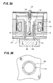
- This linear compressor comprises a cylinder 10 supported by a support mechanism 90 in a hermetic vessel 100, a piston 20 slidably supported by the cylinder 10 along an axial direction thereof, a spring member 60 for applying an axial force to the piston 20, a linear motor 70 having a stator 50 connected to the cylinder 10 and a moving member 40 supported in a reciprocating path formed in the stator 50 such that the moving member 40 can reciprocate, a connecting rod 30 which is one of connecting mechanisms connected to the piston 20, and a head cover 80 having a suction valve, a discharge valve and the like for charging and discharging solvent to and from a compression chamber 13 of the cylinder 10.
- One end of the connecting rod 30 is connected to the spring member 60, and the moving member 40 is also connected to the spring member 60.
- the hermetic vessel 100 comprises a container for accommodating essential constituent elements of the linear compressor.
- a refrigerant is supplied to space 101 in the hermetic vessel 100 from a suction tube (not shown), and the refrigerant is introduced toward an intake side of the head cover 80.
- a compressed refrigerant is discharged out from a discharge tube (not shown) connected to the hermetic vessel 100 through the head cover 80.
- the support mechanism 90 comprises a spring-support plate 92 fixed to an interior of the hermetic vessel 100, and a plurality of coil springs 91 mounted on the spring-support plate 92 for supporting the cylinder 10.
- the coil springs 91 functions to prevent vibration from being transmitted from the cylinder 10 to the hermetic vessel 100.
- the cylinder 10 comprises a flange 11 against which the coil springs 91 abut, and a boss 12 projecting from a center of this flange 11 toward one end (upward in Fig.1) of the cylinder 10.
- the flange 11 and the boss 12 are integrally formed.
- a sliding face 14d against which the piston 20 abuts is formed on an inner peripheral surface of the boss 12.
- the piston 20 comprises a cylindrical body having an outer peripheral surface 24 (Fig.2) slidably supported by the sliding face 14d of the cylinder 10.
- An inner surface of the cylinder 10 is formed with a recess, and a center of gravity of the inner surface is located at a bottom 21.
- a ball seat 22 having a spherical recess is formed in an axial center of the bottom 21.
- a compression chamber 13 is formed between a head of the piston 20 and the head cover 80 closely connected to the flange 11 of the cylinder 10.
- the spring member 60 comprises a disc-like member in this embodiment.
- a peripheral edge of the spring member 60 is fixed, a portion of the spring member 60 from its peripheral edge to the center thereof is resiliently deformed.
- the linear motor 70 comprises the moving member 40 and the stator 50.
- the stator 50 comprises an inner yoke 51 and an outer yoke 52.
- the inner yoke 51 comprises a cylindrical body and fixed to the boss 12 in a circumscribing manner.
- a coil 53 is accommodated in the inner yoke 51 and connected to a power source (not shown).
- the outer yoke 52 comprises a cylindrical body covering the inner yoke 51, and is fixed to the flange 11 of the cylinder 10.
- a reciprocating path 54 having small space is formed between an inner peripheral surface of the outer yoke 52 and an outer peripheral surface of the inner yoke 51.
- a peripheral edge of the spring member 60 is supported on and fixed to the outer yoke 52.
- the moving member 40 of the linear motor 70 comprises a permanent magnet 41, and a cylindrical holding member 42 for holding the permanent magnet 41.
- the cylindrical holding member 42 is accommodated in the reciprocating path 54 such that the holding member 42 can reciprocate therein.
- the cylindrical holding member 42 comprises a peripheral edge 42a for fixing the permanent magnet 41 and a disc 42b integrally connected to the peripheral edge 42a. A center portion of the disc 42b is fixed to a center portion of the spring member 60.
- the permanent magnet 41 is disposed at a position opposed to the coil 53, and a constant fine gap is formed therebetween.
- the inner yoke 51 and the outer yoke 52 are disposed coaxially so as to uniformly keep the fine gap over the entire circumferential region.
- the connecting rod 30 of the connecting mechanism comprises a slender rod, and is formed at its one end (lower end in the Fig.1) with a spherical end 31.
- the other end of the connecting rod 30 is connected to the center portion of the disc 42b of the cylindrical holding member 42, and fixed to the center portion of the spring member 60.
- the other end of the connecting rod 30 is detachably connected to the center of the disc 42b.
- the spherical end 31 comprises a ball rotatably fitted in the ball seat 22 of the piston 20.
- the head cover 80 is fixed to an end surface of the flange 11 of the cylinder 10 through a valve plate 81.
- a suction valve (not shown) that can be brought into communication with the compression chamber 13, a discharge valve (not shown) and the like are assembled into the valve plate 81.
- the suction valve and the discharge valve are respectively connected to intake-side space (not shown) and discharge-side space (not shown) provided in the head cover 80.
- a suction tube and a discharge tube are respectively connected to the intake-side space and the discharge-side space.
- the refrigerant is introduced from the suction tube into the hermetic vessel 100.
- the refrigerant introduced into the hermetic vessel 100 enters the compression chamber 13 from the intake-side space of the head cover 80 through the suction valve assembled into the valve plate 70.
- the refrigerant is compressed by the piston 20 and discharged out from the discharge tube (not shown) through the discharge valve assembled into the valve plate 70 and the discharge-side space of the head cover 80. Vibration of the cylinder 10 caused by a reciprocating motion is restrained by the coil springs 91.
- the connecting rod 30 can rock with respect to the piston 20. Therefore, even if a force trying to incline the piston 20 even slightly, e.g., a pressing force of the spring member 60 or a magnetic attraction force generated in the linear motor 70 is applied to the connecting rod 30, the outer peripheral surface of the piston 20 follows the inner peripheral surface of the cylinder 10, and the sliding surface pressure is not increased. This can enhance the efficiency and reliability of the compressor. Since the ball seat 22 is provided in the vicinity of the center of gravity of the piston 20, rotation moment of the piston 20 itself is not applied, and the sliding surface pressure can be reduced further. Since the moving member 40 of the linear motor is fixed to and supported by the spring member 60, the spring member 60 can receive the magnetic attraction force generated between the moving member 40 and the stator 50, a force applied to the piston 20 is reduced, and the sliding loss can also be reduced.
- This dynamic pressure groove 23 comprises bent (angle) herringbone grooves arranged in a plurality of rows formed in an outer peripheral surface 24 of the piston 20.
- the piston 20 is held by a dynamic pressure generated in the dynamic pressure groove 23 as the piston 20 reciprocates, thereby minimizing the sliding contact between the inner peripheral surface of the cylinder 10 and the outer peripheral surface of the piston 20.
- this dynamic pressure groove 23 the efficiency and the reliability of the compressor can further be enhanced.
- Figs.3A and 3B show another embodiment of the fluid bearing.
- This bearing is a gas bearing utilizing a high-pressure refrigerant gas.
- This gas bearing includes introducing paths 14 and through holes 15.
- the introducing path 14 includes a ring groove 14b formed in an end surface of the flange 11 of the cylinder 10, a plurality of introducing holes 14c formed in the boss 12 of the cylinder 10, and communication holes 14a which are in communication with the ring groove 14b from the discharge-side space of the head cover 80.
- Each of the through holes 15 comprises a plurality of holes which bring the introducing holes 14c and the sliding face 14d of the cylinder 10 into communication with each other.
- the high-pressure refrigerant gas from the introducing path 14 is injected from the plurality of through holes 15 to hold the piston 20.
Landscapes
- Engineering & Computer Science (AREA)
- Mechanical Engineering (AREA)
- General Engineering & Computer Science (AREA)
- Compressors, Vaccum Pumps And Other Relevant Systems (AREA)
- Compressor (AREA)
Abstract
Description
Claims (6)
- A linear compressor comprising a cylinder supported in a hermetic vessel by a support mechanism, a piston slidably supported by said cylinder along its axial direction, a spring member for applying an axial force to said piston, a connecting mechanism for connecting said piston and said spring member with each other, and a linear motor having a stator coupled to said cylinder and a moving member coupled to said piston, wherein said connecting mechanism is connected to said piston such said connecting mechanism can rock with respect to said piston.
- A linear compressor according to claim 1, wherein said connecting mechanism comprises a connecting rod having one end connected to said piston and the other end connected to said spring member, said one end of said connecting rod is formed into a spherical end, said piston is provided at its axially center portion with a ball seat for holding said spherical end.
- A linear compressor according to claim 2, wherein said ball seat is formed in the vicinity of a center of gravity of said piston.
- A linear compressor comprising a cylinder supported in a hermetic vessel by a support mechanism, a piston slidably supported by said cylinder along its axial direction, a spring member for applying an axial force to said piston, and a linear motor having a coupling portion coupled to said cylinder and a moving member coupled to said piston, wherein a fluid bearing is formed between said piston and said cylinder.
- A linear compressor according to claim 4, wherein said fluid bearing comprises a dynamic pressure groove formed in an outer peripheral surface of said piston.
- A linear compressor according to claim 4, wherein said fluid bearing comprises an introducing path for introducing a discharged gas into said cylinder, and a through hole formed in said cylinder, and said through hole brings said introducing path and a sliding surface of said cylinder.
Applications Claiming Priority (2)
| Application Number | Priority Date | Filing Date | Title |
|---|---|---|---|
| JP2000034676A JP2001227461A (en) | 2000-02-14 | 2000-02-14 | Linear compressor |
| JP2000034676 | 2000-02-14 |
Publications (2)
| Publication Number | Publication Date |
|---|---|
| EP1126171A2 true EP1126171A2 (en) | 2001-08-22 |
| EP1126171A3 EP1126171A3 (en) | 2002-07-10 |
Family
ID=18558975
Family Applications (1)
| Application Number | Title | Priority Date | Filing Date |
|---|---|---|---|
| EP01103267A Withdrawn EP1126171A3 (en) | 2000-02-14 | 2001-02-12 | Linear compressor |
Country Status (3)
| Country | Link |
|---|---|
| US (1) | US6506032B2 (en) |
| EP (1) | EP1126171A3 (en) |
| JP (1) | JP2001227461A (en) |
Cited By (10)
| Publication number | Priority date | Publication date | Assignee | Title |
|---|---|---|---|---|
| WO2003081041A1 (en) * | 2002-03-22 | 2003-10-02 | Empresa Brasileira De Compressores S/A - Embraco | Reciprocating compressor driven by a linear motor |
| DE102004061941A1 (en) * | 2004-12-22 | 2006-07-06 | Aerolas Gmbh, Aerostatische Lager- Lasertechnik | Axially driven piston-cylinder unit |
| CN100335781C (en) * | 2002-09-25 | 2007-09-05 | Lg电子株式会社 | Frame of reciprocating compressor |
| WO2008028799A1 (en) * | 2006-09-07 | 2008-03-13 | BSH Bosch und Siemens Hausgeräte GmbH | Linear compressor having compressed gas supported piston |
| US7896623B2 (en) | 2004-12-23 | 2011-03-01 | Bsh Bosch Und Siemens Hausgeraete Gmbh | Linear compressor with spring arrangement |
| US7913613B2 (en) | 2004-12-22 | 2011-03-29 | Bsh Bosch Und Siemens Hausgeraete Gmbh | Piston/cylinder unit |
| US8038418B2 (en) | 2004-12-23 | 2011-10-18 | Bsh Bosch Und Siemens Hausgeraete Gmbh | Linear compressor |
| GB2490180A (en) * | 2011-04-18 | 2012-10-24 | Hyperspin Ltd | Pump with actively driven valves |
| CN105332895A (en) * | 2015-11-23 | 2016-02-17 | 珠海格力节能环保制冷技术研究中心有限公司 | Compressor and piston assembly thereof |
| EP3812585A1 (en) * | 2019-10-24 | 2021-04-28 | LG Electronics Inc. | Linear compressor |
Families Citing this family (33)
| Publication number | Priority date | Publication date | Assignee | Title |
|---|---|---|---|---|
| BR0004286B1 (en) * | 2000-09-06 | 2008-11-18 | oil pump for reciprocating hermetic compressor. | |
| TW504546B (en) * | 2000-10-17 | 2002-10-01 | Fisher & Amp Paykel Ltd | A linear compressor |
| KR100701871B1 (en) * | 2000-11-10 | 2007-04-02 | 삼성광주전자 주식회사 | Piston-drive part of linear compressor and method of producting the same |
| KR100386277B1 (en) * | 2001-04-04 | 2003-06-02 | 엘지전자 주식회사 | Reciprocating compressor |
| WO2003068999A1 (en) * | 2002-02-14 | 2003-08-21 | Billiton Sa Limited | Delivery system for heap bioleaching |
| BR0203507A (en) * | 2002-07-03 | 2004-05-25 | Brasil Compressores Sa | Linear motor stator, ring element pack and electric motor stator forming process |
| CN100359168C (en) * | 2003-05-20 | 2008-01-02 | 乐金电子(天津)电器有限公司 | Method for producing compressing top of reciprocating compressor |
| NZ526361A (en) * | 2003-05-30 | 2006-02-24 | Fisher & Paykel Appliances Ltd | Compressor improvements |
| KR100527176B1 (en) * | 2004-03-09 | 2005-11-09 | 삼성광주전자 주식회사 | Linear compressor |
| US7032400B2 (en) * | 2004-03-29 | 2006-04-25 | Hussmann Corporation | Refrigeration unit having a linear compressor |
| US20060083627A1 (en) * | 2004-10-19 | 2006-04-20 | Manole Dan M | Vapor compression system including a swiveling compressor |
| WO2006049510A2 (en) * | 2004-11-02 | 2006-05-11 | Fisher & Paykel Appliances Limited | Linear compressor |
| DE102004062301A1 (en) * | 2004-12-23 | 2006-07-13 | BSH Bosch und Siemens Hausgeräte GmbH | Linear compressor and drive unit for it |
| DE102004062300A1 (en) * | 2004-12-23 | 2006-07-13 | BSH Bosch und Siemens Hausgeräte GmbH | linear compressor |
| DE102004062302A1 (en) * | 2004-12-23 | 2006-07-13 | BSH Bosch und Siemens Hausgeräte GmbH | Linear compressor and drive unit for it |
| US20080000348A1 (en) * | 2004-12-23 | 2008-01-03 | Bsh Bosch Und Siemens Hausgerate Gmbh | Linear Compressor |
| DE102004062305A1 (en) * | 2004-12-23 | 2006-07-13 | BSH Bosch und Siemens Hausgeräte GmbH | compressor housing |
| BRPI0500338A (en) * | 2005-02-01 | 2006-09-12 | Brasil Compressores Sa | reciprocating compressor piston rod |
| JP4745768B2 (en) * | 2005-05-06 | 2011-08-10 | エルジー エレクトロニクス インコーポレイティド | Linear compressor |
| KR100712916B1 (en) * | 2005-11-10 | 2007-05-02 | 엘지전자 주식회사 | Linear compressor |
| DE102006009232A1 (en) * | 2006-02-28 | 2007-08-30 | BSH Bosch und Siemens Hausgeräte GmbH | Power supply unit for linear compressor in cooling equipment has coil spring that is expandable and compressible, and which is biased against swinging body |
| DE102006009230A1 (en) * | 2006-02-28 | 2007-08-30 | BSH Bosch und Siemens Hausgeräte GmbH | Linear compressor operation method involves applying direct current to winding to displace armature from rest position |
| DE102006040357A1 (en) * | 2006-08-29 | 2008-03-13 | BSH Bosch und Siemens Hausgeräte GmbH | linear compressor |
| DE102006052430A1 (en) * | 2006-11-07 | 2008-05-08 | BSH Bosch und Siemens Hausgeräte GmbH | Compressor with gas-bearing piston |
| KR100872428B1 (en) * | 2007-01-22 | 2008-12-08 | 엘지전자 주식회사 | Reciprocating compressor |
| JP5492917B2 (en) * | 2012-02-01 | 2014-05-14 | 株式会社豊田自動織機 | Variable capacity swash plate compressor |
| KR101454250B1 (en) * | 2012-09-19 | 2014-10-23 | 엘지전자 주식회사 | Reciprocating compressor |
| EP2700816B1 (en) | 2012-08-24 | 2016-09-28 | LG Electronics Inc. | Reciprocating compressor |
| US10100819B2 (en) * | 2016-01-27 | 2018-10-16 | Haier Us Appliance Solutions, Inc. | Linear compressor |
| US10066615B2 (en) * | 2016-08-16 | 2018-09-04 | Haier Us Appliance Solutions, Inc. | Linear compressor with a ball joint coupling |
| US10746164B2 (en) | 2018-05-10 | 2020-08-18 | Haier Us Appliance Solutions, Inc. | Linear compressor with a coupling |
| KR102228544B1 (en) * | 2020-02-05 | 2021-03-16 | 엘지전자 주식회사 | Compressor |
| KR102613226B1 (en) * | 2022-04-14 | 2023-12-14 | 엘지전자 주식회사 | Oil feeder and linear compressor including the same |
Citations (2)
| Publication number | Priority date | Publication date | Assignee | Title |
|---|---|---|---|---|
| US3303990A (en) * | 1964-02-11 | 1967-02-14 | Mechanical Tech Inc | Resonant piston compressor |
| WO1997010437A1 (en) | 1995-09-14 | 1997-03-20 | Edward Grenke | Wellhead drive brake system |
Family Cites Families (18)
| Publication number | Priority date | Publication date | Assignee | Title |
|---|---|---|---|---|
| GB392811A (en) * | 1932-10-03 | 1933-05-25 | Teves Kg Alfred | Improvements in electromagnetically actuated gas compressors |
| US1996160A (en) * | 1933-12-23 | 1935-04-02 | Teves Kg Alfred | Driving unit for fluid pumps |
| US3329334A (en) * | 1964-02-11 | 1967-07-04 | Mechanical Tech Inc | Resonant piston compressor |
| US3368850A (en) * | 1965-05-27 | 1968-02-13 | Wilcox Roy Milton | Slot type hydrostatic bearings |
| US3359872A (en) * | 1965-10-22 | 1967-12-26 | Berry W Foster | Fluid pressure seal rings |
| US3543061A (en) * | 1969-04-16 | 1970-11-24 | Philco Ford Corp | Reciprocable motor core laminations with involute and radial sections |
| US3588291A (en) * | 1969-12-05 | 1971-06-28 | Mechanical Tech Inc | Resonant piston pumps |
| DE2412943A1 (en) * | 1974-03-18 | 1975-10-02 | Rheinstahl Ag | HYDRAULIC SWIVEL DRIVE, IN PARTICULAR FOR GUNS AND / OR PROTECTED OR. GUIDED ARMS |
| JPS5830561A (en) * | 1981-08-19 | 1983-02-23 | Toshiba Corp | Manufacture of ball joint type piston used in enclosed compressor |
| NL8503037A (en) | 1985-11-06 | 1987-06-01 | Philips Nv | DEVICE WITH A HYDRODYNAMICALLY BEARING PISTON. |
| GB9311385D0 (en) * | 1993-06-02 | 1993-07-21 | Contech Int Ltd | Compressor |
| US5525845A (en) * | 1994-03-21 | 1996-06-11 | Sunpower, Inc. | Fluid bearing with compliant linkage for centering reciprocating bodies |
| PL304502A1 (en) * | 1994-07-28 | 1996-02-05 | Eda Sa | Piston/connecting-rod assembly with adjustable connecting-rod length and method of making same |
| KR100224186B1 (en) * | 1996-01-16 | 1999-10-15 | 윤종용 | Linear compressorr |
| EP0864750A4 (en) * | 1996-07-09 | 1999-06-09 | Sanyo Electric Co | Linear compressor |
| US6077054A (en) * | 1997-12-23 | 2000-06-20 | Samsung Electronics Co., Ltd. | Stator of linear compressor |
| KR100480086B1 (en) * | 1998-01-12 | 2005-06-08 | 엘지전자 주식회사 | Suction loss reduction structure of linear compressor |
| JP3083518B2 (en) * | 1998-07-03 | 2000-09-04 | 三星電子株式会社 | Structure and connection method of inner core and cylinder block of linear compressor |
-
2000
- 2000-02-14 JP JP2000034676A patent/JP2001227461A/en active Pending
-
2001
- 2001-02-12 EP EP01103267A patent/EP1126171A3/en not_active Withdrawn
- 2001-02-12 US US09/780,354 patent/US6506032B2/en not_active Expired - Lifetime
Patent Citations (2)
| Publication number | Priority date | Publication date | Assignee | Title |
|---|---|---|---|---|
| US3303990A (en) * | 1964-02-11 | 1967-02-14 | Mechanical Tech Inc | Resonant piston compressor |
| WO1997010437A1 (en) | 1995-09-14 | 1997-03-20 | Edward Grenke | Wellhead drive brake system |
Cited By (16)
| Publication number | Priority date | Publication date | Assignee | Title |
|---|---|---|---|---|
| US7316547B2 (en) | 2002-03-22 | 2008-01-08 | Empresa Brasilera De Compressores S.A. - Embraco | Reciprocating compressor driven by a linear motor |
| WO2003081041A1 (en) * | 2002-03-22 | 2003-10-02 | Empresa Brasileira De Compressores S/A - Embraco | Reciprocating compressor driven by a linear motor |
| CN100335781C (en) * | 2002-09-25 | 2007-09-05 | Lg电子株式会社 | Frame of reciprocating compressor |
| DE102004061941B4 (en) * | 2004-12-22 | 2014-02-13 | AeroLas GmbH Aerostatische Lager- Lasertechnik | Axially driven piston-cylinder unit |
| DE102004061941A1 (en) * | 2004-12-22 | 2006-07-06 | Aerolas Gmbh, Aerostatische Lager- Lasertechnik | Axially driven piston-cylinder unit |
| US7913613B2 (en) | 2004-12-22 | 2011-03-29 | Bsh Bosch Und Siemens Hausgeraete Gmbh | Piston/cylinder unit |
| US7896623B2 (en) | 2004-12-23 | 2011-03-01 | Bsh Bosch Und Siemens Hausgeraete Gmbh | Linear compressor with spring arrangement |
| US8038418B2 (en) | 2004-12-23 | 2011-10-18 | Bsh Bosch Und Siemens Hausgeraete Gmbh | Linear compressor |
| WO2008028799A1 (en) * | 2006-09-07 | 2008-03-13 | BSH Bosch und Siemens Hausgeräte GmbH | Linear compressor having compressed gas supported piston |
| GB2490180A (en) * | 2011-04-18 | 2012-10-24 | Hyperspin Ltd | Pump with actively driven valves |
| GB2490180B (en) * | 2011-04-18 | 2013-04-17 | Hyperspin Ltd | Valve assembly and method of pumping a fluid |
| EP2699800A4 (en) * | 2011-04-18 | 2015-06-24 | Hyperspin Ltd | Fluid pump and method of pumping a fluid |
| CN105332895A (en) * | 2015-11-23 | 2016-02-17 | 珠海格力节能环保制冷技术研究中心有限公司 | Compressor and piston assembly thereof |
| CN105332895B (en) * | 2015-11-23 | 2018-01-02 | 珠海格力节能环保制冷技术研究中心有限公司 | Compressor and its piston component |
| EP3812585A1 (en) * | 2019-10-24 | 2021-04-28 | LG Electronics Inc. | Linear compressor |
| US11965500B2 (en) | 2019-10-24 | 2024-04-23 | Lg Electronics Inc. | Linear compressor |
Also Published As
| Publication number | Publication date |
|---|---|
| EP1126171A3 (en) | 2002-07-10 |
| US6506032B2 (en) | 2003-01-14 |
| JP2001227461A (en) | 2001-08-24 |
| US20010014292A1 (en) | 2001-08-16 |
Similar Documents
| Publication | Publication Date | Title |
|---|---|---|
| US6506032B2 (en) | Linear compressor | |
| US6565332B2 (en) | Linear compressor | |
| US6742998B2 (en) | Linear compressor with vibration canceling spring arrangement | |
| US6273688B1 (en) | Linear compressor | |
| US6626651B2 (en) | Linear compressor | |
| EP2122170B1 (en) | Reciprocating compressor | |
| EP0979943A2 (en) | Linear compressor | |
| JPH11159453A (en) | Torsional resonance dampting structure of driving system in compressor | |
| JP2004190527A (en) | Linear compressor | |
| KR20020090138A (en) | Linear compressor | |
| JPH11343970A (en) | Electric compressor | |
| JP2002317761A (en) | Linear compressor | |
| EP1918582A2 (en) | Bearing structure in rotating machine | |
| JP2000297749A (en) | Vibration type compressor | |
| JPH10288156A (en) | Oscillating type compressor | |
| JP2001165042A (en) | Vibration type compressor | |
| JP2006118455A (en) | Drive source provided with compression mechanism compressing fluid by using output of electric motor as drive source and compressor provided with compressing mechanism | |
| JP2005106034A (en) | Linear compressor | |
| JP2004019489A (en) | Linear compressor | |
| JP2003097425A (en) | Linear compressor | |
| JPH10131855A (en) | Oscillating compressor | |
| JP2004011496A (en) | Linear compressor | |
| JPH10288155A (en) | Oscillating type compressor | |
| JP2003097445A (en) | Linear compressor for co2 refrigerant | |
| JP2008075859A (en) | Gas compressor |
Legal Events
| Date | Code | Title | Description |
|---|---|---|---|
| PUAI | Public reference made under article 153(3) epc to a published international application that has entered the european phase |
Free format text: ORIGINAL CODE: 0009012 |
|
| AK | Designated contracting states |
Kind code of ref document: A2 Designated state(s): AT BE CH CY DE DK ES FI FR GB GR IE IT LI LU MC NL PT SE TR |
|
| AX | Request for extension of the european patent |
Free format text: AL;LT;LV;MK;RO;SI |
|
| PUAL | Search report despatched |
Free format text: ORIGINAL CODE: 0009013 |
|
| AK | Designated contracting states |
Kind code of ref document: A3 Designated state(s): AT BE CH CY DE DK ES FI FR GB GR IE IT LI LU MC NL PT SE TR |
|
| AX | Request for extension of the european patent |
Free format text: AL;LT;LV;MK;RO;SI |
|
| 17P | Request for examination filed |
Effective date: 20020808 |
|
| AKX | Designation fees paid |
Designated state(s): DE FR IT |
|
| 17Q | First examination report despatched |
Effective date: 20030710 |
|
| STAA | Information on the status of an ep patent application or granted ep patent |
Free format text: STATUS: THE APPLICATION IS DEEMED TO BE WITHDRAWN |
|
| 18D | Application deemed to be withdrawn |
Effective date: 20041001 |