EP1126119B1 - Arrangement de fermeture pour portes à deux battants - Google Patents
Arrangement de fermeture pour portes à deux battants Download PDFInfo
- Publication number
- EP1126119B1 EP1126119B1 EP01301311A EP01301311A EP1126119B1 EP 1126119 B1 EP1126119 B1 EP 1126119B1 EP 01301311 A EP01301311 A EP 01301311A EP 01301311 A EP01301311 A EP 01301311A EP 1126119 B1 EP1126119 B1 EP 1126119B1
- Authority
- EP
- European Patent Office
- Prior art keywords
- door
- sequence control
- closure sequence
- pull arm
- stop member
- Prior art date
- Legal status (The legal status is an assumption and is not a legal conclusion. Google has not performed a legal analysis and makes no representation as to the accuracy of the status listed.)
- Expired - Lifetime
Links
Images

Classifications
-
- E—FIXED CONSTRUCTIONS
- E05—LOCKS; KEYS; WINDOW OR DOOR FITTINGS; SAFES
- E05F—DEVICES FOR MOVING WINGS INTO OPEN OR CLOSED POSITION; CHECKS FOR WINGS; WING FITTINGS NOT OTHERWISE PROVIDED FOR, CONCERNED WITH THE FUNCTIONING OF THE WING
- E05F5/00—Braking devices, e.g. checks; Stops; Buffers
- E05F5/12—Braking devices, e.g. checks; Stops; Buffers specially for preventing the closing of a wing before another wing has been closed
-
- E—FIXED CONSTRUCTIONS
- E05—LOCKS; KEYS; WINDOW OR DOOR FITTINGS; SAFES
- E05Y—INDEXING SCHEME RELATING TO HINGES OR OTHER SUSPENSION DEVICES FOR DOORS, WINDOWS OR WINGS AND DEVICES FOR MOVING WINGS INTO OPEN OR CLOSED POSITION, CHECKS FOR WINGS AND WING FITTINGS NOT OTHERWISE PROVIDED FOR, CONCERNED WITH THE FUNCTIONING OF THE WING
- E05Y2201/00—Constructional elements; Accessories therefore
- E05Y2201/60—Suspension or transmission members; Accessories therefore
- E05Y2201/622—Suspension or transmission members elements
- E05Y2201/686—Rods, links
Definitions
- This invention relates to a closure sequence control arrangement for a double door having first and second door leaves hinged to opposite sides of a frame, the arrangement being according to the preamble of claim 1.
- the invention also relates also to a method for controlling the closure sequence of the door leaves of a double door according to the preamble of claim 11.
- Finnish patent publication FI 102100 discloses another known closure sequence control arrangement for turnable double doors.
- the double door is provided with door closer units and swing arms and with a guide rail or the like for guiding distal ends of the swing arms with regard to the door closer units.
- Sequence control means are arranged to cooperate with the guide rail and include a connection piece arranged in the guiding rail between the ends of the swing arms and movable against the force of a spring, a support element stationarily supported to the guide rail, and a movable stop member.
- sequence control means are arranged, in cooperation with the other ends of the swing arms during the end phase of the closing movement of the door leaves, so that said stop member prevents movement of the end of the swing arm of the second door leaf in the guiding rail until the end of the swing arm of the first door leaf has, through the connection piece, acted on the stop member so that the blocking member allows closing of the second door leaf.
- Pressure is exerted by means of the end of the swing arm through the connection piece against the force of the spring of the closure sequence control means, whereby the stop member can move so as to allow opening of the second door leaf.
- An aim of the present invention is to provide a novel arrangement for turnable door leaves of a double door which ensures the desired closure order for the door leaves, is of simple construction, is reliable in operation and is easy to install and to adapt to double doors of different widths. It is also an aim of the invention to provide an arrangement by means of which a successful sequence control for doors is secured under all conditions.
- a closure sequence arrangement for a double door as claimed in the ensuing claim 1 and a method of controlling the closure sequence of a double door according to claim 11.
- allowing direction means the direction away from the hinge side of the frame to which a door leaf is hinged and the term “blocking direction” means the direction towards the hinge side of the frame to which a door leaf is hinged.
- the closure sequence control means are arranged to prevent movement of the end of the second pull arm in the guide rail means until the end of the first pull arm has affected the closure sequence control means through the connection piece so that they allow closing of the second door leaf.
- the closure sequence control means include with advantage a connection piece arranged in the guide rail means between the ends of the pull arms to be pulled against the force of a spring, a support element, which is stationarily supported to the guide rail, and a movable stop member, whereby the closure sequence control means are arranged in cooperation with said distal ends of the pull arms in the end phase of the closing movement of the door leaves so that said stop member is arranged to prevent movement of the end of the second pull arm in the guide rail means until the end of the first pull arm has by means of a pulling movement affected the closure sequence control means through the connection piece so that the stop member allows closing of the second door leaf.
- connection piece comprises an arm member and a guide element arranged at one end thereof, the arm part and/or the guide element including a counter attachment piece for an attachment piece arranged in association with the pull arm for providing a selective mechanical coupling between the connection piece and the pull arm.
- the attachment piece comprises with advantage a hook or the like and the counter attachment piece comprises a pin or the like, whereby these members can mutually provide a mechanical coupling transmitting at least pulling force.
- the hook or the like can be stationarily connected to the pull arm as an extension thereof.
- the door closer units can with advantage be fitted to the doors on opposite sides with regard to the door hinges or to the opposite side relative to the opening side of the doors. Thus a suitable geometry can be obtained for door closure sequence control according to the invention.
- the closure sequence control means include a support element, which is stationarily supported to the guide rail means, a movable stop member and a guide element fitted to the end of the connection piece on the side of the support element, whereby the support element is provided with an elongate guide opening for the stop member which is longer in the direction of movement of the end of the pull arm than perpendicular to the direction of movement.
- the stop member is arranged in the guide opening in the support element so that the stop member extends in its stopping position partly out from the guide opening into the path of movement of the end of the pull arm of the second door leaf.
- the support element includes with advantage a guide surface parallel with the direction of the guide rail means, into which the said elongate guide opening opens.
- the guide element is provided with a blocking member which is in cooperation with the guide rail means and the guide surface of the support element so that when the door leaves are open the blocking member is under the influence of the spring arranged at such a position with regard to the guide opening that it allows movement of the stop member into its releasing position when the end moves in the allowing direction, and so that at the same time it prevents movement of the stop member into its releasing position when the end is moving in the blocking direction or in the direction towards the hinge side of the frame of the door leaf.
- closure sequence control for a double door can be carried out in a very late phase of closure, whereby the sequence control occurs also in a secure way.
- the adjustment of speed by the door closers is no longer so important for the sequence control to succeed.
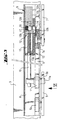
- reference numerals 1 and 2 designate two door leaves of a double door which are turnably journalled to a door frame 3 by means of hinges 3a.
- the door leaf 1 is provided with a door closer 4 having a pull arm 5 and the door leaf 2 is provided with a door closer 6 having a pull arm 7.
- the door closers are fitted to their respective door leaves on the side opposite to the hinges 3a, or on the side opposite to the opening side of the door leaves.
- the geometry is arranged so that the direction of movement of the distal end of a pull arm is changed when the door is at an angle of about 15° to its fully closed position.
- this can be chosen by suitable arrangement to be in the range of 15° to nearly 0°.
- This change in direction occurs when the fulcrum point of the arm, when the door is being closed, crosses the line drawn through the fulcrum point of the hinge 3a and the distal end 5a of the arm.
- the closure sequence control means release the second door leaf 2 to be closed. The doors are thus closed in a correct order independent of the speed control of the door closers.
- a guide rail 8 which guides the ends 5a and 7a of the pull arms 5 and 7 during the turning movements of the door leaves.
- the guide rail 8 is provided with closure sequence control means 9 which ensure that the door leaf 2, which is provided with a latch bolt 18, is closed only after the door leaf 1 has fully closed. If the door leaf 2 was able to close before door leaf 1, the door leaf 1 would not be able to turn past the door leaf 2 and the latch bolt 18 into its closed position, in which the latch bolt 18 locks the door leaves to each other.
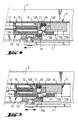
- the closure sequence control means 9 include a connection piece or connection means movable in the guide rail 8 and comprising an arm member 10 having, at one end, a counter piece 11 and, at the other end, a guide element 12.
- the counter piece 11 cooperates with the end 5a of the pull arm of the door closer of the first door leaf 1 so that transmission of pulling force is possible.
- the guide element 12 cooperates with a support element 13 fixed to the guide rail 8.
- the support element 13 includes a guide surface 13a having an elongate guide opening 13b in which a stop member 14 is received.
- the guide opening 13b is so formed that the stop member 14 can partly move out and project from the opening into a blocking position, shown in Fig.
- the guide opening 13b is elongate in the direction of movement of the guide element, whereby the stop member can move in the guide opening in the direction of the guide surface.
- the closure sequence control means 9 include the arrangement 13b,12a to allow the end 7a of the second pull arm to pass the closure sequence control means in the allowing direction, independently of the position of the guide element 12.
- the guide element 12 is provided with a blocking member 16 which cooperates with the guide rail 8 and the guide surface 13a of the support element so that when the door leaves are open the blocking member 16 is under the influence of a spring 15 arranged at such a position in the guide opening 13b that it allows movement of the stop member 14 into its releasing position when the end 7a moves in the allowing direction and prevents movement of the stop member 14 into its releasing position when the end 7a is moving in the blocking direction.
- the guide element 12 has a guide surface 12a which, together with the guide surface 13a in the support element 13 and the inner surface of the guide rail 8, guides the movements of the element 12 and the arm member 10.
- the guide element 12 also includes a bore 12b, in which the blocking member 16 serves as a blocking means and which, together with a spring 17, prevents the stop member 14 from moving away from the position of Fig. 3 into the position shown in Fig. 5 releasing the end 7a of the pull arm of the door closer of the door leaf 2.
- the spring 15 between the guide element 12 and the support element 13 retains the guide element 12 and the blocking member 16 in the position of Fig. 3 at the position of the stop member 14.
- the guide element 12 includes an extension part 12c parallel to, and located at a distance from, the guide surface 13a of the guide element which, after movement of the guide element 12 and thus of the blocking member 16 into the position shown in Fig. 5, away from the position of the stop member 14, allows movement of the stop member 14 from the guide opening 13b into a position releasing the end 7a preventing, however, movement of the stop member 14 entirely out from the guide opening 13b.
- the extension part 12c extends on both sides of the blocking member 16.
- the guide element includes a magnet 12d by means of which the stop member 14 can be retained in the releasing position of the end 7a of the pull arm shown in Fig. 5.
- the magnet is fitted in the extension part 12c, in the vicinity of the blocking member, and it retains the stop member 14 in its position in a controlled way and thereby it does not affect in any way the movements of the end 7a of the pull arm.
- the door closer 6 for the door leaf 2 is also fitted on the opposite side to the hinge 3a, i.e. on the opposite side to the opening side of the door, whereby an advantageous geometry is accomplished, in which the distal end 7a of the pull arm 7 initially moves away from the hinge as the door is closed and then, later on in the closing process, moves towards the hinge in the final closing phase.
- the operation of the closure sequence control means is as follows. Firstly the case is considered where both the door leaves 1 and 2 are open and an attempt is then made to close the door leaf 2, which includes the latch bolt 18, before the door leaf 1 is closed. In this case the door leaf 2 is turned anticlockwise (as viewed in Fig. 1) until the end 7a of its pull arm 7 moves, as shown in Fig.
- the blocking member 16 and the stop member 14 are positioned as shown in Fig. 3.
- the stop member 14 is prevented from moving into its releasing position by the blocking member 16.
- the stop member 14 thus blocks movement of the end 7a in the blocking direction (i.e. towards the hinge 3a of the door leaf 2) so the door leaf 2 remains in a partly open position. This corresponds at its largest to a turning angle of about 15°, typically from 8° to 13°, from its closed position.
- the elongated guide opening 13b is with advantage sufficiently long for the stop member 14 to move from the position of the blocking member 16 into the extension part 12c.
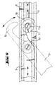
- connection parts 10, 11, 12 including the arm member 10 and the counter element 11 arranged at one end thereof.
- the counter element 11 has a counter attachment piece in the form of a pin 11a for connection or coupling to an attachment piece at the end of the pull arm 5 provided with a hook 5b in order to provide a selective mechanical coupling between the connection parts 10-12 and the pull arm 5.
- the hook 5b which extends from the end 5a, turns or pivots as shown in Fig. 6 to couple around the pin 11a of the guide element 11 and provide an attachment between these for transmitting pulling force.
- the arm member 10 or an extension thereof is fitted so as to extend through a part of the support element 13 and is fixed to the guide element 12.
- the spring 15 is arranged, in connection with the arm member or its extension, between a part of the support element 13 and the guide element 12.
- the attachment piece or the hook 5b pulls the arm member 10 against the force of the spring 15, arranged between the guide element 12 and the support element 13, into the position shown in Fig. 5.
- the blocking member 16 has moved away from the position of the stop member 14, whereby the stop member 14 can move partly out from the guide opening 13b against the extension part 12c and thus releases the end 7a of the pull arm 7 for movement in the blocking direction.
- the door closer 6 can thus now turn the door leaf 2 into its fully closed position, in which the latch bolt 18 locks the door leaves 1 and 2 to each other.
- the stop member 14 can with advantage be a ball.
- the stop member may naturally be of different form, such as of elongate form, and when needed it may include a recess for receiving the end 7a of the pull arm.
- the end 7a of the pull arm 7 and the support element 13 at least for the part including the guide opening 13b should be manufactured of a hard and wear resistant material, for instance of hardened steel.
- the arrangement according to the figures includes a one piece uniform guide rail 8.
- the guide rail could alternatively, for instance, comprise two parts so that the ends 11 and 12 of the arm member 10 are located in separate guide rails.
- the functional length of the arm member 10 can be adjusted in accordance with the width of the door opening and the door leaves in each case.
- the arm member 10 may also be shortened by truncation when the arrangement according to the invention is adapted to essentially narrower double doors.
- the support element 13 can be detachably fixed to the guide rail 8, for instance by screws, whereby by changing the position of the screws simultaneously one can change the very opening angle of the door leaves when the closure sequence control means are activated.
- the support element 13 can be arranged with regard to the guide element 12 such that the pulling force of the pull arm is transmitted to the spring as pulling and not as pressing as shown in the attached figures.
Claims (12)
- Agencement de commande du cycle de fermeture d'une porte à doubles battants comprenant un premier et un deuxième battants (1, 2) articulés sur charnières sur les côtés opposés d'un encadrement de porte, l'agencement comprenant une première unité ferme-porte (4) comportant un premier bras de traction (5) pour fermer le premier battant de porte (1), une deuxième unité ferme-porte (6) comportant un deuxième bras de traction (7) pour fermer le deuxième battant de porte (2), un moyen de rail de guidage (8) pour guider les extrémités (5a, 7a) des bras de traction (5, 7) par rapport aux unités ferme-portes, et des moyens de commande du cycle de fermeture (9) agencés, en coopération avec le moyen de rail de guidage (8) et dans lesquels sont accueillies les extrémités des bras de traction, pour commander la phase finale de fermeture des battants de porte (1, 2) de manière à ce qu'ils se ferment dans un certain ordre, caractérisé en ce que les moyens de commande du cycle de fermeture (9) comprennent un agencement (13b, 12a) pour permettre à l'extrémité (7a) du deuxième bras de traction de se déplacer au-delà des moyens de commande du cycle de fermeture (9) dans une direction d'autorisation à l'écart du côté charnières de l'encadrement sur lequel le deuxième battant de porte (2) est articulé sur charnières et empêchant sélectivement le mouvement de l'extrémité (7a) du deuxième bras de traction au-delà du moyen de commande du cycle de fermeture (9) dans une direction opposée de blocage vers le côté charnière de l'encadrement de porte sur lequel le deuxième battant (2) est articulé sur charnières.
- Agencement de commande du cycle de fermeture selon la revendication 1, caractérisé en ce que le moyen de commande du cycle de fermeture (9) comprend un moyen de connexion (10, 11) agencé dans le moyen de rail de guidage (8) entre les extrémités (5a, 7a) des bras de traction pouvant se déplacer contre la force d'un ressort (15), un élément de support (13), qui est supporté de façon stationnaire sur le moyen de rail de guidage (8), un élément de butée mobile (14) et un élément de guidage (12) monté à l'extrémité du moyen de connexion (10, 11) du côté de l'extrémité du deuxième bras de traction et pouvant se déplacer sur l'élément de support (13), en ce que l'élément de support (13) comporte une ouverture de guidage allongée (13b) pour l'élément de butée (14) qui est plus longue dans la direction du mouvement de l'extrémité (7a) du bras de traction que dans la direction perpendiculaire à ladite direction du mouvement, et en ce que l'élément de butée (14) est agencé dans ladite ouverture de guidage (13b) de façon que, dans une position de butée, il s'étend partiellement vers l'extérieur à partir de l'ouverture de guidage (13b) dans le chemin de mouvement de l'extrémité (7a) du bras de traction du deuxième battant de porte (2).
- Agencement de commande du cycle de fermeture selon la revendication 2, caractérisé en ce que l'élément de support (13) comprend une surface de guidage (13a), parallèle à la direction du moyen de rail de guidage (8), dans lequel ladite ouverture de guide allongée (13b) débouche, et en ce que l'élément de guidage (12) est pourvu d'un élément de blocage (16), coopérant avec le moyen de rail de guidage (8) et la surface de guidage (13a) de l'élément de support, de telle façon que, quand les battants de porte sont ouverts l'élément de blocage (16) et sous l'influence du ressort (15) agencé à une position telle par rapport à l'ouverture de guidage (13b) qu'il permet le mouvement de l'élément de butée (14) dans sa position de libération quand l'extrémité (7a) du deuxième bras de traction (7) se déplace dans la direction d'autorisation et en ce qu'il empêche le mouvement de l'élément de butée (14) dans sa position de libération quand l'extrémité (7a) du deuxième bras de traction (7) se déplace dans la direction de blocage.
- Agencement de commande du cycle de fermeture selon la revendication 3, caractérisé en ce que l'élément de guidage (12) comprend une partie d'extension (12c) s'étendant de façon parallèle à la surface de guidage (13a) de l'élément de support et espacée par rapport à celui-ci pour permettre le mouvement de l'élément de butée (14) dans sa position de libération mais pour empêcher l'élément de butée (14) de ce déplacer entièrement hors de l'ouverture de guidage (13b), ladite partie d'extension (12c) s'étendant dans la direction du moyen de rail de guidage (8) des deux côtés de l'élément de blocage (16).
- Agencement de commande du cycle de fermeture selon la revendication 4, caractérisé en ce que l'élément de guidage (12) comprend un aimant (12d) à proximité de l'élément de blocage (16) pour retenir l'élément de butée (14) à sa position de libération.
- Agencement de commande du cycle de fermeture selon la revendication 4 ou 5, caractérisé en ce que l'élément de blocage (16) comprend une bille (16) qui est chargée par ressort (17) dans la direction de l'élément de blocage (14).
- Agencement de commande du cycle de fermeture selon la revendication 2, caractérisé en ce que le moyen de connexion (10, 11) comprend un élément de bras allongé (10) fixé de manière amovible à ses extrémités opposées à l'élément de guidage (12) et à une contre-pièce (11) qui coopère avec l'extrémité (5a) du bras de traction du premier battant de porte (1).
- Agencement de commande du cycle de fermeture selon la revendication 2, caractérisé en ce que les moyens de commande du cycle de fermeture (9) sont agencés dans la phase finale du mouvement de fermeture des battants de porte pour coopérer avec les extrémités distales (5a, 7a) des bras de traction de telle façon que le dit élément de butée (14) est agencé pour éviter le mouvement de l'extrémité (7a) du deuxième bras de traction dans le moyen de rail de guidage (8) jusqu'à ce que de l'extrémité (5a) du premier bras de traction ait agi au moyen d'un mouvement de traction à travers le moyen de connexion (10, 11, 12) sur l'élément de butée (14) de telle façon que l'élément de butée (14) permette la fermeture du deuxième battant de porte (2).
- Agencement de commande du cycle de fermeture selon la revendication 1, caractérisé en ce que le moyen de commande du cycle de fermeture comprend des moyens de connexion (10, 11, 12) comprenant un élément de bras (10) et un contre-élément (11) agencé à une extrémité de celui-ci, en ce que l'élément de bras (10) et/ou le contre-élément (11) comprend une pièce de contre-fixation (11a) pour une pièce de fixation (5b) agencée en connexion avec le premier bras de traction (5) pour fournir un accouplement mécanique sélectif entre les moyens de connexion (10, 11, 12) et le premier bras de traction (5), en ce que la pièce de fixation comprend un crochet ou analogue (5b) et la pièce de contre-fixation comprend une goupille ou analogue (11a), et en ce que le crochet ou analogue (5b) est en connexion stationnaire avec le premier bras de traction (5) en tant qu'extension de celui-ci.
- Agencement de commande du cycle de fermeture selon l'une quelconque des revendications précédentes, caractérisé en ce que les unités ferme-portes (4, 6) sont montées de façon à être sur le côté opposé par rapport aux charnières (3a) des battants de porte, ou sur les côtés opposés par rapport au côté d'ouverture des portes.
- Procédé de commande du cycle de fermeture des premier et deuxième battants (1, 2) d'une porte à doubles battants qui sont articulés sur charnières sur les côtés opposés d'un encadrement de porte, l'agencement de porte comprenant une première unité ferme-porte (4) comportant un premier bras de traction (5) pour fermer le premier battant de porte (1), une deuxième unité ferme-porte (6) comportant un deuxième bras de traction (7) pour fermer le deuxième battant de porte (2), des moyens de rail de guidage (8) pour les extrémités de guidage (5a, 7a) des bras de traction (5, 7) par rapport aux unités ferme-portes, et un moyen de commande du cycle de fermeture (9) agencé, en coopération avec le moyen de rail de guidage (8) et les extrémités des bras de traction accueillies dans celui-ci, pour commander la phase finale de fermeture des battants de porte (1, 2) de façon à ce qu'ils se ferment dans un certain ordre, caractérisé en ce que le cycle de fermeture de l'extrémité distale (7a) du deuxième bras de traction (7) se déplace au-delà de l'extrémité d'un élément de butée (14) dans une direction d'autorisation à l'écart du côté charnières de l'encadrement sur lequel le deuxième battant de porte (2) est articulé sur charnières après quoi la direction de mouvements de l'extrémité (7a) est inversée ou modifiée de manière à être dans la direction du côté charnières de l'encadrement sur lequel le deuxième battant de porte (2) est articulé sur charnières, et l'élément de butée (14) empêche le mouvement de ladite extrémité distale (7a) du deuxième bras de traction (7) dans cette direction jusqu'à ce que le ladite extrémité distale (5a) du premier bras de traction (5) fournisse un effet de libération sur l'élément de butée (14).
- Procédé selon la revendication 11, caractérisé en ce que l'extrémité distale (5a) du premier bras de traction (5) fournit un effet de libération sur l'élément de butée (14) en fournissant un effet de traction sur le moyen de commande du cycle de fermeture (9).
Applications Claiming Priority (2)
| Application Number | Priority Date | Filing Date | Title |
|---|---|---|---|
| FI20000373A FI20000373A0 (fi) | 2000-02-18 | 2000-02-18 | Ovensulkemisjärjestely pariovia varten |
| FI20000373 | 2000-02-18 |
Publications (3)
| Publication Number | Publication Date |
|---|---|
| EP1126119A2 EP1126119A2 (fr) | 2001-08-22 |
| EP1126119A3 EP1126119A3 (fr) | 2002-11-13 |
| EP1126119B1 true EP1126119B1 (fr) | 2005-06-08 |
Family
ID=8557602
Family Applications (1)
| Application Number | Title | Priority Date | Filing Date |
|---|---|---|---|
| EP01301311A Expired - Lifetime EP1126119B1 (fr) | 2000-02-18 | 2001-02-15 | Arrangement de fermeture pour portes à deux battants |
Country Status (5)
| Country | Link |
|---|---|
| US (1) | US6401393B2 (fr) |
| EP (1) | EP1126119B1 (fr) |
| AT (1) | ATE297496T1 (fr) |
| DE (1) | DE60111286T2 (fr) |
| FI (1) | FI20000373A0 (fr) |
Cited By (1)
| Publication number | Priority date | Publication date | Assignee | Title |
|---|---|---|---|---|
| US8225458B1 (en) | 2001-07-13 | 2012-07-24 | Hoffberg Steven M | Intelligent door restraint |
Families Citing this family (18)
| Publication number | Priority date | Publication date | Assignee | Title |
|---|---|---|---|---|
| AR030763A1 (es) | 2001-09-19 | 2003-09-03 | Amilcar Felix Sosa | Dispositivo autoportante para abisagrar hacia lados opuestos |
| FI111407B (fi) * | 2002-02-01 | 2003-07-15 | Abloy Oy | Ovensuljinjärjestely kääntyvien pariovien sulkeutumisen tahdistusta varten |
| AU2004319687B2 (en) * | 2004-05-13 | 2011-12-15 | McKercher, Darren John Mr | Sequential closing system for safety storage cabinets |
| DE102005062051B4 (de) * | 2005-12-22 | 2008-07-10 | Geze Gmbh | Vorrichtung zur Schließfolgeregelung für zweiflügelige Drehtüren |
| EP1801336A1 (fr) * | 2005-12-22 | 2007-06-27 | GEZE GmbH | Dispositif coordinateur de fermeture |
| US20070157432A1 (en) * | 2006-01-11 | 2007-07-12 | Glenn Weinstein | Magnetic hinge |
| US8336535B2 (en) * | 2006-04-20 | 2012-12-25 | Whirlpool Corporation | French door cooking appliance closure system |
| DE102009021097A1 (de) | 2009-05-13 | 2010-11-18 | Assa Abloy Sicherheitstechnik Gmbh | Vorrichtung zur Schließfolgeregelung |
| AT510683B1 (de) * | 2010-11-23 | 2012-06-15 | Walter Ing Degelsegger | Vorrichtung für das steuern der schliessfolge von zweiflügeligen schwenktüren |
| DE102013000969C5 (de) | 2013-01-22 | 2019-03-07 | Assa Abloy Sicherheitstechnik Gmbh | Schließfolgeregelungseinrichtung für eine zweiflügelige Tür |
| US8595980B1 (en) * | 2013-03-04 | 2013-12-03 | I-Tek Metal Mfg. Co., Ltd. | Door coordinator |
| US9109388B2 (en) * | 2013-03-15 | 2015-08-18 | Door Controls International | Door coordinator accessory mounting bracket |
| DE102013112946A1 (de) * | 2013-11-22 | 2015-05-28 | Dorma Deutschland Gmbh | Schließfolgeregelung für eine zweiflügelige Tür |
| WO2015150174A1 (fr) | 2014-03-31 | 2015-10-08 | Assa Abloy Entrance Systems Ab | Porte à deux battants comprenant un frein de coordination |
| US10138668B1 (en) * | 2017-05-25 | 2018-11-27 | Hung Chin Architectural Hardware Co. | Position adjustment apparatus |
| WO2019035964A1 (fr) * | 2017-08-16 | 2019-02-21 | Hoffman Enclosures, Inc. | Dispositif de verrouillage pour enceintes |
| EP3987139A1 (fr) * | 2019-06-24 | 2022-04-27 | ASSA ABLOY Entrance Systems AB | Système de porte à double battant |
| US20210363797A1 (en) * | 2020-05-21 | 2021-11-25 | Hoffman Enclosures, Inc. | Interlock for Enclosures |
Family Cites Families (13)
| Publication number | Priority date | Publication date | Assignee | Title |
|---|---|---|---|---|
| US3822506A (en) * | 1973-05-21 | 1974-07-09 | Door Controls | Door coordinating device |
| US3895461A (en) * | 1974-03-11 | 1975-07-22 | Door Controls | Door coordinator assembly |
| US4429492A (en) * | 1982-01-26 | 1984-02-07 | Leigh Products, Inc. | Door coordinator |
| DE3329543A1 (de) * | 1983-08-16 | 1985-02-28 | Geze Gmbh, 7250 Leonberg | Vorrichtung zur regelung der schliessfolge von zweifluegeligen tueren |
| DE3336739A1 (de) * | 1983-10-08 | 1985-04-25 | Dorma-Baubeschlag Gmbh & Co Kg, 5828 Ennepetal | Schliessfolgevorrichtung fuer eine zweifluegelige tuer |
| DE8810389U1 (fr) * | 1988-08-17 | 1988-09-29 | Gretsch-Unitas Gmbh Baubeschlaege, 7257 Ditzingen, De | |
| DE3941455A1 (de) * | 1988-12-22 | 1990-06-28 | Geze Gmbh & Co | Vorrichtung zur regelung der schliessfolge von zweifluegeligen tueren |
| US4949505A (en) * | 1989-05-26 | 1990-08-21 | Von Duprin, Inc. | Door cordinator |
| DE4016283C1 (fr) * | 1990-05-21 | 1991-09-19 | Dorma Gmbh & Co Kg, 5828 Ennepetal, De | |
| FR2759409B1 (fr) * | 1997-02-07 | 1999-04-30 | Bourdeau | Dispositif d'actionnement en ouverture et fermeture des battants d'un volet ou d'une porte de baie de batiments |
| FI102100B (fi) * | 1997-03-26 | 1998-10-15 | Abloy Oy | Ovensulkemisjärjestely pariovia varten |
| US5944399A (en) * | 1998-07-06 | 1999-08-31 | Eagle Manufacturing Company | Safety cabinet with self-closing and sequencing door mechanism |
| DE19901769A1 (de) * | 1999-01-18 | 2000-07-20 | Geze Gmbh | Vorrichtung zur Schließfolgeregelung einer zweiflügeligen Tür |
-
2000
- 2000-02-18 FI FI20000373A patent/FI20000373A0/fi not_active IP Right Cessation
-
2001
- 2001-02-15 AT AT01301311T patent/ATE297496T1/de not_active IP Right Cessation
- 2001-02-15 DE DE60111286T patent/DE60111286T2/de not_active Expired - Lifetime
- 2001-02-15 EP EP01301311A patent/EP1126119B1/fr not_active Expired - Lifetime
- 2001-02-16 US US09/788,130 patent/US6401393B2/en not_active Expired - Lifetime
Cited By (3)
| Publication number | Priority date | Publication date | Assignee | Title |
|---|---|---|---|---|
| US8225458B1 (en) | 2001-07-13 | 2012-07-24 | Hoffberg Steven M | Intelligent door restraint |
| US9045927B1 (en) | 2001-07-13 | 2015-06-02 | Steven M. Hoffberg | Intelligent door restraint |
| US9121217B1 (en) | 2001-07-13 | 2015-09-01 | Steven M. Hoffberg | Intelligent door restraint |
Also Published As
| Publication number | Publication date |
|---|---|
| FI20000373A0 (fi) | 2000-02-18 |
| DE60111286D1 (de) | 2005-07-14 |
| EP1126119A3 (fr) | 2002-11-13 |
| ATE297496T1 (de) | 2005-06-15 |
| DE60111286T2 (de) | 2006-05-18 |
| US6401393B2 (en) | 2002-06-11 |
| US20010015032A1 (en) | 2001-08-23 |
| EP1126119A2 (fr) | 2001-08-22 |
Similar Documents
| Publication | Publication Date | Title |
|---|---|---|
| EP1126118B1 (fr) | Arrangement de fermeture pour portes à deux battants | |
| EP1126119B1 (fr) | Arrangement de fermeture pour portes à deux battants | |
| EP0867587B1 (fr) | Coordinateur de fermeture de portes à double battants | |
| DK1333142T3 (en) | Door closing arrangement for controlling the closing sequence of two-leaf pivoting doors | |
| EP1258590B1 (fr) | Coordinateur de fermeture de portes à double battants | |
| CZ305992A3 (en) | Device for controlling both swinging and sliding movements of a door of motor vehicles for passenger transport, particularly of railway stock | |
| US11851941B2 (en) | Hold-open arrester arrangement having a hold-open function to hold a door open | |
| US6036239A (en) | Door security arrangement | |
| DE102006028881B4 (de) | Vorrichtung zur Schließfolgeregelung für zweiflügelige Drehtüren | |
| CZ307494B6 (cs) | Zařízení pro regulaci pořadí zavírání dvoukřídlých dveří | |
| NO337283B1 (no) | Dørlås med hakereile | |
| EP1870550A2 (fr) | Dispositif de commande de la séquence de fermeture de portes rotatives à deux battants | |
| GB2317201A (en) | Linkage for up-and-over automatic door lock mechanism | |
| ITRM940627A1 (it) | Serratura di sicurezza a funzionamento elettrico e manuale | |
| GB2271607A (en) | Security device | |
| KR20000018838U (ko) | 도어용 안전걸이구 | |
| PL208182B1 (pl) | Regulator kolejności zamykania skrzydeł drzwiowych | |
| WO1994009237A1 (fr) | Dispositif de securite |
Legal Events
| Date | Code | Title | Description |
|---|---|---|---|
| PUAI | Public reference made under article 153(3) epc to a published international application that has entered the european phase |
Free format text: ORIGINAL CODE: 0009012 |
|
| AK | Designated contracting states |
Kind code of ref document: A2 Designated state(s): AT BE CH CY DE DK ES FI FR GB GR IE IT LI LU MC NL PT SE TR |
|
| AX | Request for extension of the european patent |
Free format text: AL;LT;LV;MK;RO;SI |
|
| PUAL | Search report despatched |
Free format text: ORIGINAL CODE: 0009013 |
|
| AK | Designated contracting states |
Kind code of ref document: A3 Designated state(s): AT BE CH CY DE DK ES FI FR GB GR IE IT LI LU MC NL PT SE TR |
|
| AX | Request for extension of the european patent |
Free format text: AL;LT;LV;MK;RO;SI |
|
| 17P | Request for examination filed |
Effective date: 20030310 |
|
| AKX | Designation fees paid |
Designated state(s): AT BE CH CY DE DK ES FI FR GB GR IE IT LI LU MC NL PT SE TR |
|
| GRAP | Despatch of communication of intention to grant a patent |
Free format text: ORIGINAL CODE: EPIDOSNIGR1 |
|
| GRAS | Grant fee paid |
Free format text: ORIGINAL CODE: EPIDOSNIGR3 |
|
| GRAA | (expected) grant |
Free format text: ORIGINAL CODE: 0009210 |
|
| AK | Designated contracting states |
Kind code of ref document: B1 Designated state(s): AT BE CH CY DE DK ES FI FR GB GR IE IT LI LU MC NL PT SE TR |
|
| PG25 | Lapsed in a contracting state [announced via postgrant information from national office to epo] |
Ref country code: FI Free format text: LAPSE BECAUSE OF FAILURE TO SUBMIT A TRANSLATION OF THE DESCRIPTION OR TO PAY THE FEE WITHIN THE PRESCRIBED TIME-LIMIT Effective date: 20050608 Ref country code: NL Free format text: LAPSE BECAUSE OF FAILURE TO SUBMIT A TRANSLATION OF THE DESCRIPTION OR TO PAY THE FEE WITHIN THE PRESCRIBED TIME-LIMIT Effective date: 20050608 Ref country code: TR Free format text: LAPSE BECAUSE OF FAILURE TO SUBMIT A TRANSLATION OF THE DESCRIPTION OR TO PAY THE FEE WITHIN THE PRESCRIBED TIME-LIMIT Effective date: 20050608 Ref country code: AT Free format text: LAPSE BECAUSE OF FAILURE TO SUBMIT A TRANSLATION OF THE DESCRIPTION OR TO PAY THE FEE WITHIN THE PRESCRIBED TIME-LIMIT Effective date: 20050608 Ref country code: BE Free format text: LAPSE BECAUSE OF FAILURE TO SUBMIT A TRANSLATION OF THE DESCRIPTION OR TO PAY THE FEE WITHIN THE PRESCRIBED TIME-LIMIT Effective date: 20050608 Ref country code: CH Free format text: LAPSE BECAUSE OF FAILURE TO SUBMIT A TRANSLATION OF THE DESCRIPTION OR TO PAY THE FEE WITHIN THE PRESCRIBED TIME-LIMIT Effective date: 20050608 Ref country code: LI Free format text: LAPSE BECAUSE OF FAILURE TO SUBMIT A TRANSLATION OF THE DESCRIPTION OR TO PAY THE FEE WITHIN THE PRESCRIBED TIME-LIMIT Effective date: 20050608 |
|
| REG | Reference to a national code |
Ref country code: GB Ref legal event code: FG4D |
|
| REG | Reference to a national code |
Ref country code: CH Ref legal event code: EP |
|
| REF | Corresponds to: |
Ref document number: 60111286 Country of ref document: DE Date of ref document: 20050714 Kind code of ref document: P |
|
| REG | Reference to a national code |
Ref country code: IE Ref legal event code: FG4D |
|
| REG | Reference to a national code |
Ref country code: SE Ref legal event code: TRGR |
|
| PG25 | Lapsed in a contracting state [announced via postgrant information from national office to epo] |
Ref country code: GR Free format text: LAPSE BECAUSE OF FAILURE TO SUBMIT A TRANSLATION OF THE DESCRIPTION OR TO PAY THE FEE WITHIN THE PRESCRIBED TIME-LIMIT Effective date: 20050908 Ref country code: DK Free format text: LAPSE BECAUSE OF FAILURE TO SUBMIT A TRANSLATION OF THE DESCRIPTION OR TO PAY THE FEE WITHIN THE PRESCRIBED TIME-LIMIT Effective date: 20050908 |
|
| PG25 | Lapsed in a contracting state [announced via postgrant information from national office to epo] |
Ref country code: PT Free format text: LAPSE BECAUSE OF FAILURE TO SUBMIT A TRANSLATION OF THE DESCRIPTION OR TO PAY THE FEE WITHIN THE PRESCRIBED TIME-LIMIT Effective date: 20051114 |
|
| NLV1 | Nl: lapsed or annulled due to failure to fulfill the requirements of art. 29p and 29m of the patents act | ||
| REG | Reference to a national code |
Ref country code: CH Ref legal event code: PL |
|
| PG25 | Lapsed in a contracting state [announced via postgrant information from national office to epo] |
Ref country code: IE Free format text: LAPSE BECAUSE OF NON-PAYMENT OF DUE FEES Effective date: 20060215 |
|
| PG25 | Lapsed in a contracting state [announced via postgrant information from national office to epo] |
Ref country code: LU Free format text: LAPSE BECAUSE OF NON-PAYMENT OF DUE FEES Effective date: 20060228 Ref country code: MC Free format text: LAPSE BECAUSE OF NON-PAYMENT OF DUE FEES Effective date: 20060228 |
|
| ET | Fr: translation filed | ||
| PLBE | No opposition filed within time limit |
Free format text: ORIGINAL CODE: 0009261 |
|
| STAA | Information on the status of an ep patent application or granted ep patent |
Free format text: STATUS: NO OPPOSITION FILED WITHIN TIME LIMIT |
|
| 26N | No opposition filed |
Effective date: 20060309 |
|
| REG | Reference to a national code |
Ref country code: IE Ref legal event code: MM4A |
|
| PG25 | Lapsed in a contracting state [announced via postgrant information from national office to epo] |
Ref country code: CY Free format text: LAPSE BECAUSE OF FAILURE TO SUBMIT A TRANSLATION OF THE DESCRIPTION OR TO PAY THE FEE WITHIN THE PRESCRIBED TIME-LIMIT Effective date: 20050608 |
|
| PG25 | Lapsed in a contracting state [announced via postgrant information from national office to epo] |
Ref country code: ES Free format text: LAPSE BECAUSE OF NON-PAYMENT OF DUE FEES Effective date: 20060228 |
|
| REG | Reference to a national code |
Ref country code: FR Ref legal event code: PLFP Year of fee payment: 16 |
|
| REG | Reference to a national code |
Ref country code: FR Ref legal event code: PLFP Year of fee payment: 17 |
|
| PGFP | Annual fee paid to national office [announced via postgrant information from national office to epo] |
Ref country code: DE Payment date: 20170207 Year of fee payment: 17 Ref country code: FR Payment date: 20170112 Year of fee payment: 17 Ref country code: SE Payment date: 20170213 Year of fee payment: 17 |
|
| PGFP | Annual fee paid to national office [announced via postgrant information from national office to epo] |
Ref country code: GB Payment date: 20170215 Year of fee payment: 17 |
|
| PGFP | Annual fee paid to national office [announced via postgrant information from national office to epo] |
Ref country code: IT Payment date: 20170221 Year of fee payment: 17 |
|
| REG | Reference to a national code |
Ref country code: DE Ref legal event code: R119 Ref document number: 60111286 Country of ref document: DE |
|
| REG | Reference to a national code |
Ref country code: SE Ref legal event code: EUG |
|
| GBPC | Gb: european patent ceased through non-payment of renewal fee |
Effective date: 20180215 |
|
| PG25 | Lapsed in a contracting state [announced via postgrant information from national office to epo] |
Ref country code: SE Free format text: LAPSE BECAUSE OF NON-PAYMENT OF DUE FEES Effective date: 20180216 |
|
| REG | Reference to a national code |
Ref country code: FR Ref legal event code: ST Effective date: 20181031 |
|
| PG25 | Lapsed in a contracting state [announced via postgrant information from national office to epo] |
Ref country code: DE Free format text: LAPSE BECAUSE OF NON-PAYMENT OF DUE FEES Effective date: 20180901 |
|
| PG25 | Lapsed in a contracting state [announced via postgrant information from national office to epo] |
Ref country code: GB Free format text: LAPSE BECAUSE OF NON-PAYMENT OF DUE FEES Effective date: 20180215 Ref country code: IT Free format text: LAPSE BECAUSE OF NON-PAYMENT OF DUE FEES Effective date: 20180215 Ref country code: FR Free format text: LAPSE BECAUSE OF NON-PAYMENT OF DUE FEES Effective date: 20180228 |