EP1125822A1 - Vehicle electric power assist steering system and method using angle based torque estimation - Google Patents
Vehicle electric power assist steering system and method using angle based torque estimation Download PDFInfo
- Publication number
- EP1125822A1 EP1125822A1 EP01300955A EP01300955A EP1125822A1 EP 1125822 A1 EP1125822 A1 EP 1125822A1 EP 01300955 A EP01300955 A EP 01300955A EP 01300955 A EP01300955 A EP 01300955A EP 1125822 A1 EP1125822 A1 EP 1125822A1
- Authority
- EP
- European Patent Office
- Prior art keywords
- steering
- torque
- electric motor
- function
- assist
- Prior art date
- Legal status (The legal status is an assumption and is not a legal conclusion. Google has not performed a legal analysis and makes no representation as to the accuracy of the status listed.)
- Granted
Links
- 238000000034 method Methods 0.000 title claims abstract description 14
- 230000006870 function Effects 0.000 claims description 49
- 238000010586 diagram Methods 0.000 description 3
- 238000005259 measurement Methods 0.000 description 3
- 230000004044 response Effects 0.000 description 3
- 230000000712 assembly Effects 0.000 description 2
- 238000000429 assembly Methods 0.000 description 2
- 230000000694 effects Effects 0.000 description 2
- 230000007704 transition Effects 0.000 description 2
- 230000008030 elimination Effects 0.000 description 1
- 238000003379 elimination reaction Methods 0.000 description 1
- 238000005265 energy consumption Methods 0.000 description 1
- 230000007246 mechanism Effects 0.000 description 1
- 230000008569 process Effects 0.000 description 1
Images


Classifications
-
- B—PERFORMING OPERATIONS; TRANSPORTING
- B62—LAND VEHICLES FOR TRAVELLING OTHERWISE THAN ON RAILS
- B62D—MOTOR VEHICLES; TRAILERS
- B62D6/00—Arrangements for automatically controlling steering depending on driving conditions sensed and responded to, e.g. control circuits
- B62D6/08—Arrangements for automatically controlling steering depending on driving conditions sensed and responded to, e.g. control circuits responsive only to driver input torque
- B62D6/10—Arrangements for automatically controlling steering depending on driving conditions sensed and responded to, e.g. control circuits responsive only to driver input torque characterised by means for sensing or determining torque
-
- B—PERFORMING OPERATIONS; TRANSPORTING
- B62—LAND VEHICLES FOR TRAVELLING OTHERWISE THAN ON RAILS
- B62D—MOTOR VEHICLES; TRAILERS
- B62D5/00—Power-assisted or power-driven steering
- B62D5/04—Power-assisted or power-driven steering electrical, e.g. using an electric servo-motor connected to, or forming part of, the steering gear
- B62D5/0457—Power-assisted or power-driven steering electrical, e.g. using an electric servo-motor connected to, or forming part of, the steering gear characterised by control features of the drive means as such
- B62D5/046—Controlling the motor
- B62D5/0463—Controlling the motor calculating assisting torque from the motor based on driver input
Definitions
- the present invention generally relates to vehicle steering systems, and more particularly relates to an electric power assist steering system and method of controlling electric power steering assist for a steered vehicle.
- Conventional steering of a wheeled motor vehicle is typically achieved by the vehicle operator (driver) rotating a steering wheel that is arranged in the passenger compartment of the vehicle to turn the steerable road wheels.
- Conventional steering systems generally include a rack and pinion type steering assembly operatively coupled to the road wheels and a steering column coupled between the steering wheel and the rack and pinion assembly for converting angular rotation of the steering wheel into a sliding motion on the rack to effect steering operation of the road wheels.
- driver effort i.e., torque
- conventional steering systems typically include a power assisted actuator that assists the operator with rotation of the steering wheel to overcome opposing forces such as road load forces on the road wheels and friction forces in the steering assembly.
- the amount of power assistance generally varies depending on the speed of the vehicle and the amount of effort applied by the vehicle operator to the steering wheel.
- Conventional power assist steering systems typically employ either hydraulic power assist or electric power assist.
- the electric power assist steering system offers variable assist capabilities, more efficient energy consumption, reduced mechanism complexity, increased reliability, and responsive on-demand steering assist, as well as other advantages.
- the electric power assist steering (EPAS) system employs an electric motor for applying a controlled amount of torque to the steering assembly to assist the operator with angular rotation of the steering wheel.
- the conventional electric power assist steering system is generally configured with a feedback control system that electrically amplifies the driver steering torque input to the steering system to realise improved steering comfort and performance.
- the electric power assist steering system typically includes a rotatable steering wheel, a steering column, a rack and pinion assembly, a gear box assembly, and an electric motor.
- the conventional electric power assist steering system also employs a pinion torque sensor, as well as various other sensors.
- the pinion torque sensor is generally located between the steering column and the rack and pinion assembly and senses the amount of torque applied at the pinion.
- the measured pinion torque serves as an approximation of the input torque applied to the steering wheel by the vehicle operator and is commonly used to determine the amount of torque assist to be provided by the electric motor.
- the amount of torque assist is typically calculated from a tunable non-linear boost curve which generates a control command signal to control the electric motor to achieve the desired level of power steering assist.
- an electric power assist steering system for a vehicle that provides torque assist to the vehicle operator at a reduced cost.
- an electric power assist steering system for controlling the amount of electric power assist without requiring the use of a torque sensor. It is further desirable to achieve optimal steering assist performance with an electric power assist steering system.
- an electric power assist steering system having a steering assembly including a steering wheel connected to a steering column, and an electric motor operatively engaged with the steering assembly for supplying torque assist.
- a steering angle sensor is employed for sensing an angular position of the steering assembly.
- the steering system has a torque estimator for determining an estimated torque signal as a function of the sensed angular position of the steering assembly, and a motor controller for generating a motor control signal as a function of the estimated torque.
- a method which includes the steps of sensing angular position of the steering assembly, estimating a torque signal as a function of the sensed angular position, generating a motor control signal as a function of the estimated torque, and applying the motor control signal to an electric motor to generate steering torque assist. Accordingly, the system and method of the present invention reduces the complexity and cost of the electric power assist steering system by eliminating the need for a pinion torque sensor, without sacrificing vehicle steering performance.
- an electric power assist steering (EPAS) system 10 equipped with a control system 30 according to the present invention is illustrated for use in steering a wheeled vehicle, such as a motor vehicle.
- the steering system 10 is described herein in connection with the power assisted steering of a pair of road wheels 28, such as the front wheels of the motor vehicle, adapted to be engaged in friction contact with the ground, such as a roadway.
- the steering system 10 of the present invention may be employed to steer any number of front and/or rear wheels of a steered vehicle.
- the electric power assist steering system 10 has a steering assembly which includes a rotatable steering wheel 12 that is generally disposed in the passenger compartment of the vehicle and is manually rotatable by the driver of the vehicle to steer the road wheels 28.
- the steering assembly also includes a steering column 14 operatively coupled to steering wheel 12.
- the steering column 14 has a rotary shaft 15 that rotates in synchronisation with the steering wheel 12.
- Shaft 15 is preferably directly connected to steering wheel 12.
- the steering assembly as shown employs an intermediate shaft 16 and a pinion shaft 18, both operatively engaged with steering column 14.
- Steering column 14, intermediate shaft 16, and pinion shaft 18 are preferably interconnected via universal joints as is well-known in the vehicle steering art. While steering column 14, intermediate shaft 16, and pinion shaft 18 are shown in this example, it should be appreciated that any number of rotating shafts and various mechanical assemblies may be coupled to steering wheel 12 to actuate the steerable road wheels 28 in response to actuation of steering wheel 12.
- An electric motor 20 is coupled to the pinion shaft 18 to provide torque assist to shaft 18 such as to assist the driver of the vehicle in rotating the steering wheel 12.
- the electric motor 20 provides power (torque) assist to aid in the steering of the road wheels 28 so as to reduce the amount of effort required by the driver.
- Power steering assist reduces the effects of steering assembly friction and road load.
- the pinion shaft 18 is coupled at one end to a pinion gear assembly 28 for converting angular rotation of the pinion shaft 18 to linear movement on a rack 24.
- the rack 24 is coupled on opposite ends to tie rods 26 and connector rods 27 which are movable to control left and right rotation of road wheels 28.
- the steering wheel 12, steering column 14, shafts 16 and 18, pinion gear assembly 22, rack 24, tie rods 26, connector shafts 27, and road wheels 28 may include a conventional vehicle steering assembly.
- the electric power assist steering system 10 has a control system 30 that controls the amount of torque generated by the electric motor 20.
- Control system 30 preferably includes one or more microprocessor based controllers having memory programmed to operate control routines, process input signals, estimate torque signals, and generate control signals for controlling the electric motor input command signal U to achieve the desired torque assist T a .
- the control system 30 is preferably configured with feedback control and feedforward control as described herein. While control system 30 employs one or more programmed controllers, it should be appreciated that various analogue and digital circuits could be employed to estimate torque and control the electric motor power assist without departing from the teachings of the present invention.
- steering system 10 further includes a steering angle sensor 32 for measuring the steering column position angle ⁇ c .
- the steering angle sensor 32 senses angular position of the rotatable shaft 15 of the steering column 14.
- the measured steering column position angle ⁇ c provides a measurement of the angular position of the steering wheel 12.
- the measured steering column angle ⁇ c is input to the control system 30 and is used to estimate torque signals according to the present invention.
- the control system 30 also monitors the angular velocity ⁇ ⁇ m of electric motor 20.
- the electric motor velocity ⁇ ⁇ m may be measured directly from the electric motor input command signal U , or may be remotely sensed by an angular position sensor or angular speed sensor.
- control system 30 is illustrated therein for controlling the electric power assist steering system 10 according to the present invention.
- the control system 30 is shown made up of various control devices, each programmed with control routines for performing one or more designated control functions to generate a desired electric motor torque assist to achieve enhanced vehicle steering performance.
- the control system 30 incorporates a function block 10 representative of the electric power steering assist system shown having a driver input 32 which is the driver applied torque.
- the electric power assist steering system 10 receives the driver input 32 in the form of a torque applied to the steering wheel 12.
- steering system 10 receives a motor input command signal U .
- Electric power assist steering system 10 further produces the sensed steering wheel position angle ⁇ c and electric motor speed ⁇ ⁇ m .
- the control system 30 includes a non-linear boost curve look-up table 34 which receives an estimated driver torque signal and generates a feedforward signal that is added to a feedback signal to produce the motor input command signal U .
- Boost curve look-up table 34 preferably includes a non-linear boost curve which maps the amount of motor input command signal U versus estimated driver torque T d est at various vehicle speeds. Accordingly, the boost curve is responsive to a sensed vehicle speed (not shown).
- the control system 30 further includes a torque estimator 40 for estimating the driver torque T d est applied to the steering wheel 12, and for further estimating the pinion torque T c est applied to the pinion shaft 18.
- the torque estimator 40 receives, as inputs, the sensed angular position ⁇ c of the steering column and the electric motor input command signal U . It should be appreciated that, by estimating the driver torque T d est and pinion torque T c est , the torque estimator 40 provides torque estimations which allow for elimination of a conventional pinion torque sensor, thereby reducing the overall cost and complexity of the steering system 10.
- the control system 30 further includes a feedback controller 38 coupled in a feedback loop 44.
- Feedback controller 38 receives, as inputs, the estimated driver torque T d est and estimated pinion torque T c est , as well as the sensed angular position ⁇ c , the motor angular velocity ⁇ ⁇ m , and the desired torque T d est .
- feedback controller 38 produces a feedback signal in feedback loop 44 that is summed with the feedforward signal T a des at summer 42.
- Summer 42 sums the feedback signal on feedback loop 44 with the feedforward signal on feedforward loop 46 to produce the motor input command signal U that drives the electric motor 20.
- the feedforward loop 46 includes a friction compensation filter 36 which receives the estimated driver torque T d est and filters out the undesired high frequency signals to compensate for friction forces, such as road load friction and steering column friction.
- the friction compensation filtered output is supplied as an input to the boost curve look-up table 34 which in turn produces the desired torque signal T a des.
- the control system 30 includes both a feedback loop 44 and feedforward loop 46.
- the feedback loop 44 advantageously provides robust stability of the closed-loop system and allows for compensation for component changes, while the feedforward loop 46 provides fast steady state response and attenuation of friction. Accordingly, if the torque estimator 40 fails to perform the intended operation, the control system 30 will remain stable. Similarly, if the feedback loop 44 fails to perform the closed-loop system will likewise remain stable.
- the torque estimator 40 includes a number of function blocks containing measured transfer functions including G 21 , G -1 / 21 , G 22 , G -1 / 31 , and G 32 .
- the transfer functions G 21 , G -1 / 21 , G 22 , G -1 / 31 , and G 32 are measured based on the dynamic relationship of selected steering system outputs divided by selected inputs, and are defined as follows.
- Transfer function G 31 is the relationship of the steering angle output ⁇ c divided by the driver torque input T d .
- Transfer function G 32 is the relationship of the steering angle output ⁇ c divided by the motor control input command signal U.
- Transfer function G 21 is the relationship of the pinion torque output T c divided by the driver torque input T d .
- Transfer function G 22 is the relationship of the pinion torque output T c divided by the motor input control command signal U.
- the torque estimator 40 receives as inputs the motor input command signal U and the sensed angular position signal ⁇ c .
- the motor input command signal U is input to transfer function G 22 in function block 50 and is also input to transfer function G 32 in function block 52.
- the output of function block 50 is input to a negative input of summer 54 and to a positive input of summer 60, while the output of function block 52 is input to a negative input of summer 56.
- Summer 56 subtracts the output of function block 52 from the measured steering column angular position ⁇ c and provides the resultant subtraction as an input to function block 58.
- Function block 58 includes the product of transfer function G 21 and G -1 / 31 .
- G -1 / 31 is the inverse of transfer function G 31 .
- the output of function block 58 is input to a positive input of summer 60, while the other positive input of summer 60 receives the output of function block 50.
- Summer 60 sums the two inputs to produce the estimated pinion torque T c est , which is one output of torque estimator 40.
- the estimated pinion torque T c est is further input to a positive terminal of summer 54. Accordingly, summer 54 subtracts the output of function block 50 from the estimated pinion torque T c est and provides the subtraction as an input to function block 62.
- Function block 62 includes a transfer function G -1 / 21 , which is the inverse of transfer function G 21 , and produces the estimated driver torque T d est , as a second output of torque estimator 40. Accordingly, the torque estimator 40 estimates both a driver torque estimate T d est , as well as a pinion torque estimate T c est , which are then used to generate the motor control command signal U to control the electric power assist steering system 10 according to the present invention.
- the resultant torque estimation equations (1) and (2) are derived from modelling dynamic relationships of the steering system which are established based on Newton's laws of motion.
- the dynamic model of the steering system is defined by the measured transfer functions as described above.
- the control methodology 70 includes step 72 of determining each of transfer functions G 21 , G -1 / 21 , G 22 , and G 32 .
- the transfer functions can be determined with the steering system off line by applying a known driver torque input to the steering wheel and measuring selected inputs and outputs and then computing the transfer function by dividing the selected output over the selected input for the corresponding defined functions.
- methodology 70 proceeds to step 74 to measure the steering angle ⁇ c with steering angle sensor 32.
- step 76 the estimated driver torque T d est and estimated pinion torque T c est are determined by the torque estimator 40.
- step 78 the estimated driver torque T d est is compensated for friction forces in the feedforward loop 46 by passing the estimated torque T d est through the friction compensation filter.
- step 80 the desired assist torque T a des is generated based on estimated driver torque T d est and vehicle speed according to the mapped data provided in the boost curve.
- An optional step 82 is provided for calculating the equilibrium point based on the estimated driver torque T d est , estimated pinion torque T c est , steering angle ⁇ c , motor velocity ⁇ ⁇ m , and desired assist torque T a des . It should be appreciated that by providing for an equilibrium point, the present feedback signal more accurately determines the driver torque by providing an average signal to allow for the realisation of smooth transitions during dynamic transitions of the vehicle operation.
- control methodology 70 proceeds to step 84 to calculate the motor command signal U to control the electric motor to achieve a controlled amount of power steering assist. It should be appreciated that the motor command signal U is applied to motor in step 86.
- the electric power assist steering system 10 of the present invention advantageously provides for electric power steering assist to a steering system of a vehicle by estimating the torque applied to the steering system by the driver, without requiring a conventional pinion torque sensor.
- the present invention advantageously reduces the cost and complexity of the steering system.
- the torque estimation provides for fast and stable control without sacrificing steering performance. While one example of a steering assembly is shown herein, it should be appreciated that other steering assemblies may be employed in connection with the control system described herein without departing from the spirit of the present invention.
Landscapes
- Engineering & Computer Science (AREA)
- Chemical & Material Sciences (AREA)
- Combustion & Propulsion (AREA)
- Transportation (AREA)
- Mechanical Engineering (AREA)
- Steering Control In Accordance With Driving Conditions (AREA)
- Power Steering Mechanism (AREA)
Abstract
Description
- The present invention generally relates to vehicle steering systems, and more particularly relates to an electric power assist steering system and method of controlling electric power steering assist for a steered vehicle.
- Reference is made to US Patent application nos. 09/504743 and 09/505373.
- Conventional steering of a wheeled motor vehicle is typically achieved by the vehicle operator (driver) rotating a steering wheel that is arranged in the passenger compartment of the vehicle to turn the steerable road wheels. Conventional steering systems generally include a rack and pinion type steering assembly operatively coupled to the road wheels and a steering column coupled between the steering wheel and the rack and pinion assembly for converting angular rotation of the steering wheel into a sliding motion on the rack to effect steering operation of the road wheels. In order to reduce the amount of driver effort (i.e., torque) that is required to rotate the steering wheel, conventional steering systems typically include a power assisted actuator that assists the operator with rotation of the steering wheel to overcome opposing forces such as road load forces on the road wheels and friction forces in the steering assembly. The amount of power assistance generally varies depending on the speed of the vehicle and the amount of effort applied by the vehicle operator to the steering wheel. Conventional power assist steering systems typically employ either hydraulic power assist or electric power assist. In contrast to hydraulic power assist systems, the electric power assist steering system offers variable assist capabilities, more efficient energy consumption, reduced mechanism complexity, increased reliability, and responsive on-demand steering assist, as well as other advantages.
- The electric power assist steering (EPAS) system employs an electric motor for applying a controlled amount of torque to the steering assembly to assist the operator with angular rotation of the steering wheel. The conventional electric power assist steering system is generally configured with a feedback control system that electrically amplifies the driver steering torque input to the steering system to realise improved steering comfort and performance. The electric power assist steering system typically includes a rotatable steering wheel, a steering column, a rack and pinion assembly, a gear box assembly, and an electric motor. The conventional electric power assist steering system also employs a pinion torque sensor, as well as various other sensors. The pinion torque sensor is generally located between the steering column and the rack and pinion assembly and senses the amount of torque applied at the pinion. The measured pinion torque serves as an approximation of the input torque applied to the steering wheel by the vehicle operator and is commonly used to determine the amount of torque assist to be provided by the electric motor. The amount of torque assist is typically calculated from a tunable non-linear boost curve which generates a control command signal to control the electric motor to achieve the desired level of power steering assist.
- While the employment of a pinion torque sensor for measuring pinion torque is typically acceptable for controlling the amount of power steering assist provided by the electric motor during steady state operation, the conventional torque sensor is relatively expensive and therefore adds to the overall cost and complexity of the steering system. Additionally, the pinion torque measurement typically deviates dramatically from the actual driver applied torque during dynamic transients, particularly when the amount of motor generated assist torque is significant, thereby not permitting optimal steering assist.
- Accordingly, it is desired to provide for an electric power assist steering system for a vehicle that provides torque assist to the vehicle operator at a reduced cost. In particular, it is desired to provide for an electric power assist steering system for controlling the amount of electric power assist without requiring the use of a torque sensor. It is further desirable to achieve optimal steering assist performance with an electric power assist steering system.
- In accordance with the teachings of the present invention, a steering system and method of controlling the steering of a vehicle are provided. According to one aspect of the present invention, an electric power assist steering system is provided having a steering assembly including a steering wheel connected to a steering column, and an electric motor operatively engaged with the steering assembly for supplying torque assist. A steering angle sensor is employed for sensing an angular position of the steering assembly. The steering system has a torque estimator for determining an estimated torque signal as a function of the sensed angular position of the steering assembly, and a motor controller for generating a motor control signal as a function of the estimated torque.
- According to another aspect of the present invention, a method is provided which includes the steps of sensing angular position of the steering assembly, estimating a torque signal as a function of the sensed angular position, generating a motor control signal as a function of the estimated torque, and applying the motor control signal to an electric motor to generate steering torque assist. Accordingly, the system and method of the present invention reduces the complexity and cost of the electric power assist steering system by eliminating the need for a pinion torque sensor, without sacrificing vehicle steering performance.
- The present invention will now be described further, by way of example, with reference to the accompanying drawings, in which:
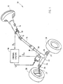
- FIG. 1 is a diagrammatic view of an electric power assist steering system for a wheeled vehicle according to the present invention;
- FIG. 2 is a block diagram of the control system for controlling the electric power assist steering system;
- FIG. 3 is a block diagram illustrating functions of the torque estimator for estimating driver torque and pinion torque according to the present invention; and
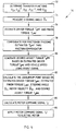
- FIG. 4 is a flow diagram illustrating a methodology for controlling the electric power assist steering system according to the present invention.
-
- Referring to FIG. 1, an electric power assist steering (EPAS)
system 10 equipped with acontrol system 30 according to the present invention is illustrated for use in steering a wheeled vehicle, such as a motor vehicle. Thesteering system 10 is described herein in connection with the power assisted steering of a pair ofroad wheels 28, such as the front wheels of the motor vehicle, adapted to be engaged in friction contact with the ground, such as a roadway. However, it should be appreciated that thesteering system 10 of the present invention may be employed to steer any number of front and/or rear wheels of a steered vehicle. - The electric power
assist steering system 10 has a steering assembly which includes arotatable steering wheel 12 that is generally disposed in the passenger compartment of the vehicle and is manually rotatable by the driver of the vehicle to steer theroad wheels 28. The steering assembly also includes asteering column 14 operatively coupled tosteering wheel 12. Thesteering column 14 has arotary shaft 15 that rotates in synchronisation with thesteering wheel 12. Shaft 15 is preferably directly connected tosteering wheel 12. The steering assembly as shown employs anintermediate shaft 16 and apinion shaft 18, both operatively engaged withsteering column 14.Steering column 14,intermediate shaft 16, andpinion shaft 18 are preferably interconnected via universal joints as is well-known in the vehicle steering art. Whilesteering column 14,intermediate shaft 16, andpinion shaft 18 are shown in this example, it should be appreciated that any number of rotating shafts and various mechanical assemblies may be coupled tosteering wheel 12 to actuate thesteerable road wheels 28 in response to actuation ofsteering wheel 12. - An
electric motor 20 is coupled to thepinion shaft 18 to provide torque assist toshaft 18 such as to assist the driver of the vehicle in rotating thesteering wheel 12. Theelectric motor 20 provides power (torque) assist to aid in the steering of theroad wheels 28 so as to reduce the amount of effort required by the driver. Power steering assist reduces the effects of steering assembly friction and road load. Thepinion shaft 18 is coupled at one end to apinion gear assembly 28 for converting angular rotation of thepinion shaft 18 to linear movement on arack 24. Therack 24 is coupled on opposite ends to tierods 26 andconnector rods 27 which are movable to control left and right rotation ofroad wheels 28. It should be appreciated that thesteering wheel 12,steering column 14,shafts pinion gear assembly 22,rack 24,tie rods 26,connector shafts 27, androad wheels 28 may include a conventional vehicle steering assembly. - The electric power
assist steering system 10 has acontrol system 30 that controls the amount of torque generated by theelectric motor 20.Control system 30 preferably includes one or more microprocessor based controllers having memory programmed to operate control routines, process input signals, estimate torque signals, and generate control signals for controlling the electric motor input command signal U to achieve the desired torque assist Ta . Thecontrol system 30 is preferably configured with feedback control and feedforward control as described herein. Whilecontrol system 30 employs one or more programmed controllers, it should be appreciated that various analogue and digital circuits could be employed to estimate torque and control the electric motor power assist without departing from the teachings of the present invention. - In addition,
steering system 10 further includes asteering angle sensor 32 for measuring the steering column position angle c . Thesteering angle sensor 32 senses angular position of therotatable shaft 15 of thesteering column 14. The measured steering column position angle c provides a measurement of the angular position of thesteering wheel 12. The measured steering column angle c is input to thecontrol system 30 and is used to estimate torque signals according to the present invention. Thecontrol system 30 also monitors the angular velocity ˙ m ofelectric motor 20. The electric motor velocity ˙ m may be measured directly from the electric motor input command signal U, or may be remotely sensed by an angular position sensor or angular speed sensor. - Referring to FIG. 2, the
control system 30 is illustrated therein for controlling the electric powerassist steering system 10 according to the present invention. Thecontrol system 30 is shown made up of various control devices, each programmed with control routines for performing one or more designated control functions to generate a desired electric motor torque assist to achieve enhanced vehicle steering performance. As shown, thecontrol system 30 incorporates afunction block 10 representative of the electric power steering assist system shown having adriver input 32 which is the driver applied torque. The electric powerassist steering system 10 receives thedriver input 32 in the form of a torque applied to thesteering wheel 12. In addition,steering system 10 receives a motor input command signal U. Electric powerassist steering system 10 further produces the sensed steering wheel position angle c and electric motor speed ˙ m . - The
control system 30 includes a non-linear boost curve look-up table 34 which receives an estimated driver torque signal and generates a feedforward signal that is added to a feedback signal to produce the motor input command signal U. Boost curve look-up table 34 preferably includes a non-linear boost curve which maps the amount of motor input command signal U versus estimated driver torque Tdest at various vehicle speeds. Accordingly, the boost curve is responsive to a sensed vehicle speed (not shown). - The
control system 30 further includes atorque estimator 40 for estimating the driver torque Tdest applied to thesteering wheel 12, and for further estimating the pinion torque Tcest applied to thepinion shaft 18. Thetorque estimator 40 receives, as inputs, the sensed angular position c of the steering column and the electric motor input command signal U. It should be appreciated that, by estimating the driver torque Tdest and pinion torque Tcest, thetorque estimator 40 provides torque estimations which allow for elimination of a conventional pinion torque sensor, thereby reducing the overall cost and complexity of thesteering system 10. - The
control system 30 further includes afeedback controller 38 coupled in afeedback loop 44.Feedback controller 38 receives, as inputs, the estimated driver torque Tdest and estimated pinion torque Tcest, as well as the sensed angular position c , the motor angular velocity ˙ m , and the desired torque Tdest. In response to the inputs,feedback controller 38 produces a feedback signal infeedback loop 44 that is summed with the feedforward signal Tades atsummer 42.Summer 42 sums the feedback signal onfeedback loop 44 with the feedforward signal onfeedforward loop 46 to produce the motor input command signal U that drives theelectric motor 20. - The
feedforward loop 46 includes afriction compensation filter 36 which receives the estimated driver torque Tdest and filters out the undesired high frequency signals to compensate for friction forces, such as road load friction and steering column friction. The friction compensation filtered output is supplied as an input to the boost curve look-up table 34 which in turn produces the desired torque signal Tades. Accordingly, thecontrol system 30 includes both afeedback loop 44 andfeedforward loop 46. It should be appreciated that thefeedback loop 44 advantageously provides robust stability of the closed-loop system and allows for compensation for component changes, while thefeedforward loop 46 provides fast steady state response and attenuation of friction. Accordingly, if thetorque estimator 40 fails to perform the intended operation, thecontrol system 30 will remain stable. Similarly, if thefeedback loop 44 fails to perform the closed-loop system will likewise remain stable. - With particular reference to FIG. 3, the torque estimation functions performed by the
torque estimator 40 are shown in detail for determining the estimated driver torque Tdest and estimated pinion torque Tcest. Thetorque estimator 40 includes a number of function blocks containing measured transfer functions including G 21, G -1 / 21 , G 22, G -1 / 31 , and G 32. The transfer functions G 21, G -1 / 21 , G 22, G -1 / 31 , and G 32 are measured based on the dynamic relationship of selected steering system outputs divided by selected inputs, and are defined as follows. Transfer function G 31 is the relationship of the steering angle output c divided by the driver torque input Td . Transfer function G 32 is the relationship of the steering angle output c divided by the motor control input command signal U. Transfer function G 21 is the relationship of the pinion torque output Tc divided by the driver torque input Td . Transfer function G 22 is the relationship of the pinion torque output Tc divided by the motor input control command signal U. - The
torque estimator 40 receives as inputs the motor input command signal U and the sensed angular position signal c . The motor input command signal U is input to transfer function G 22 infunction block 50 and is also input to transfer function G 32 infunction block 52. The output offunction block 50 is input to a negative input ofsummer 54 and to a positive input ofsummer 60, while the output offunction block 52 is input to a negative input ofsummer 56.Summer 56 subtracts the output offunction block 52 from the measured steering column angular position c and provides the resultant subtraction as an input to functionblock 58.Function block 58 includes the product of transfer function G 21 and G -1 / 31 . G -1 / 31 is the inverse of transfer function G 31. The output offunction block 58 is input to a positive input ofsummer 60, while the other positive input ofsummer 60 receives the output offunction block 50.Summer 60 sums the two inputs to produce the estimated pinion torque Tcest, which is one output oftorque estimator 40. - The estimated pinion torque Tcest is further input to a positive terminal of
summer 54. Accordingly,summer 54 subtracts the output offunction block 50 from the estimated pinion torque Tcest and provides the subtraction as an input to functionblock 62.Function block 62 includes a transfer function G -1 / 21 , which is the inverse of transfer function G 21, and produces the estimated driver torque Tdest, as a second output oftorque estimator 40. Accordingly, thetorque estimator 40 estimates both a driver torque estimate Tdest, as well as a pinion torque estimate Tcest, which are then used to generate the motor control command signal U to control the electric powerassist steering system 10 according to the present invention. - The
torque estimator 40 is designed to perform torque estimations based on the torque estimation functions which can also be represented as follows:
- The resultant torque estimation equations (1) and (2) are derived from modelling dynamic relationships of the steering system which are established based on Newton's laws of motion. The dynamic model of the steering system is defined by the measured transfer functions as described above. By measuring the motor control input current U and steering angle position c , the estimated driver torque Tdest and estimated pinion torque Tcest are computed, without requiring a direct measurement of torque with a torque sensor.
- Referring to FIG. 4, a
control methodology 70 for controlling the electric powerassist steering system 10 with thecontrol system 30 of the present invention is illustrated therein. Thecontrol methodology 70 includesstep 72 of determining each of transfer functions G 21, G -1 / 21 , G 22, and G 32 . The transfer functions can be determined with the steering system off line by applying a known driver torque input to the steering wheel and measuring selected inputs and outputs and then computing the transfer function by dividing the selected output over the selected input for the corresponding defined functions. Once the transfer functions are determined,methodology 70 proceeds to step 74 to measure the steering angle c withsteering angle sensor 32. Instep 76, the estimated driver torque Tdest and estimated pinion torque Tcest are determined by thetorque estimator 40. Instep 78, the estimated driver torque Tdest is compensated for friction forces in thefeedforward loop 46 by passing the estimated torque Tdest through the friction compensation filter. Instep 80, the desired assist torque Tades is generated based on estimated driver torque Tdest and vehicle speed according to the mapped data provided in the boost curve. Anoptional step 82 is provided for calculating the equilibrium point based on the estimated driver torque Tdest, estimated pinion torque Tcest, steering angle c , motor velocity ˙ m, and desired assist torque Tades. It should be appreciated that by providing for an equilibrium point, the present feedback signal more accurately determines the driver torque by providing an average signal to allow for the realisation of smooth transitions during dynamic transitions of the vehicle operation. Finally,control methodology 70 proceeds to step 84 to calculate the motor command signal U to control the electric motor to achieve a controlled amount of power steering assist. It should be appreciated that the motor command signal U is applied to motor instep 86. - Accordingly, the electric power
assist steering system 10 of the present invention advantageously provides for electric power steering assist to a steering system of a vehicle by estimating the torque applied to the steering system by the driver, without requiring a conventional pinion torque sensor. By eliminating the need for a conventional pinion torque sensor, the present invention advantageously reduces the cost and complexity of the steering system. At the same time, the torque estimation provides for fast and stable control without sacrificing steering performance. While one example of a steering assembly is shown herein, it should be appreciated that other steering assemblies may be employed in connection with the control system described herein without departing from the spirit of the present invention.
Claims (10)
- An electric power assist steering system for a vehicle, comprising:a steering assembly including a steering wheel (12) connected to a steering column;a steering angle sensor (32) for sensing an angular position of the steering assembly;an electric motor (20) operatively engaged with said steering assembly for supplying steering torque assist;a torque estimator (40) for estimating a torque signal as a function of said sensed angular position of the steering assembly; anda controller (30) for generating a motor control signal as a function of said estimated torque for controlling the electric motor.
- A system as claimed in claim 1, wherein said torque estimator determines said estimated torque signal further as a function of the motor control signal input to the electric motor.
- A system as claimed in claim 2, wherein said torque estimator determines the estimated torque signal further as a function of one or more steering system transfer functions.
- A system as claimed in claim 1, wherein said torque estimator estimates a driver torque signal and a pinion torque signal.
- A system as claimed in claim 1, wherein said controller includes a feedback controller and a feedforward controller.
- A system as claimed in claim 5 further comprising a friction compensation filter coupled to said feedforward controller.
- A system as claimed in claim 1, wherein said steering assembly further includes a shaft operatively coupled to the steering column and further connected to a rack and pinion assembly, wherein said electric motor is coupled to said shaft.
- A system as claimed in claim 1, wherein said system is provided without a pinion torque sensor.
- A control system for controlling electric motor torque assist to an electric power assisted steering system for a vehicle having a steering assembly including a steering wheel connected to a steering column and an electric motor operatively engaged with the steering assembly for supplying steering torque assist, wherein said control system comprises:a steering angle sensor for sensing an angular position of the steering assembly;a torque estimator for estimating a torque signal as a function of said sensed angular position of the steering assembly; anda controller for generating a motor control signal as a function of said estimated torque for controlling the electric motor.
- A method of controlling an electric power assisted steering system having a steering assembly including a steering wheel connected to a steering column for a vehicle, said method comprising the steps of:sensing an angular position of the steering assembly;estimating a torque signal as a function of said sensed angular position of the steering assembly;generating a motor control signal as a function of said estimated torque for controlling an electric motor; andapplying said motor control signal to an electric motor to generate a controlled amount of steering torque assist.
Applications Claiming Priority (2)
| Application Number | Priority Date | Filing Date | Title |
|---|---|---|---|
| US09/505,641 US6293366B1 (en) | 2000-02-16 | 2000-02-16 | Vehicle electric power assist steering system and method using angle based torque estimation |
| US505641 | 2000-02-16 |
Publications (2)
| Publication Number | Publication Date |
|---|---|
| EP1125822A1 true EP1125822A1 (en) | 2001-08-22 |
| EP1125822B1 EP1125822B1 (en) | 2006-08-09 |
Family
ID=24011205
Family Applications (1)
| Application Number | Title | Priority Date | Filing Date |
|---|---|---|---|
| EP01300955A Expired - Lifetime EP1125822B1 (en) | 2000-02-16 | 2001-02-02 | Vehicle electric power assist steering system and method using angle based torque estimation |
Country Status (3)
| Country | Link |
|---|---|
| US (1) | US6293366B1 (en) |
| EP (1) | EP1125822B1 (en) |
| DE (1) | DE60122036T2 (en) |
Cited By (3)
| Publication number | Priority date | Publication date | Assignee | Title |
|---|---|---|---|---|
| WO2004022414A1 (en) * | 2002-09-06 | 2004-03-18 | Volkswagen Ag | Device and method for measuring torque for an electromechanical steering system |
| US7454986B2 (en) | 2002-09-06 | 2008-11-25 | Volkswagen Aktiengesellschaft | Device and method for measuring torque in an electromechanical steering system |
| CN105599806A (en) * | 2014-11-19 | 2016-05-25 | 本田技研工业株式会社 | Electric power steering apparatus and steering effort assist controlling apparatus |
Families Citing this family (21)
| Publication number | Priority date | Publication date | Assignee | Title |
|---|---|---|---|---|
| US6422335B1 (en) * | 2000-04-11 | 2002-07-23 | Trw Inc. | Method and apparatus for controlling steering feel with diagnostics |
| US6651771B2 (en) * | 2001-10-20 | 2003-11-25 | Ford Global Technologies, Llc | H-infinity control and gain scheduling method for electric power assist steering system |
| US6661191B2 (en) * | 2002-01-30 | 2003-12-09 | Visteon Global Technologies, Inc. | Method and apparatus for compensating drive current for an electric motor vehicle steering system |
| US6901320B2 (en) | 2003-01-15 | 2005-05-31 | Visteon Global Technologies, Inc. | Friction compensation in a vehicle steering system |
| US6984949B2 (en) * | 2003-06-02 | 2006-01-10 | Tm4 Inc. | System and method to selectively prevent movements of an electric vehicle |
| JP4777257B2 (en) * | 2003-12-04 | 2011-09-21 | コンティネンタル・テーベス・アクチエンゲゼルシヤフト・ウント・コンパニー・オッフェネ・ハンデルスゲゼルシヤフト | Method and apparatus for assisting a vehicle operator in stabilizing a vehicle |
| JP4967829B2 (en) * | 2007-06-04 | 2012-07-04 | 株式会社ジェイテクト | Electric power steering device |
| DE102008038891B4 (en) * | 2008-08-13 | 2017-07-20 | Volkswagen Ag | Device and method for detecting a torque on an electromechanical steering |
| US20100145579A1 (en) * | 2008-12-10 | 2010-06-10 | Honeywell International Inc. | Method and system for onboard zero offset compensation for electric power assist steering torque sensor |
| CN102490779B (en) * | 2011-11-18 | 2013-03-13 | 上海交通大学 | Digital steering wheel system with force feedback |
| US9340114B2 (en) | 2012-01-23 | 2016-05-17 | Ford Global Technologies, Llc | Electric vehicle with transient current management for DC-DC converter |
| CN103863387A (en) * | 2012-12-17 | 2014-06-18 | 诸城福田汽车科技开发有限公司 | Electric power steering device and corresponding steering system |
| US9975570B2 (en) * | 2013-02-22 | 2018-05-22 | Steering Solutions Ip Holding Corporation | Velocity signal filter with reduced lag |
| US9150246B2 (en) * | 2013-12-06 | 2015-10-06 | GM Global Technology Operations LLC | Algorithm for steering angle command to torque command conversion |
| US9278713B2 (en) * | 2013-12-11 | 2016-03-08 | GM Global Technology Operations LLC | Collision avoidance control integrated with EPS controller |
| KR101539081B1 (en) * | 2014-05-28 | 2015-07-24 | 현대모비스 주식회사 | Apparatus and method of friction compensation for mdps system |
| GB201411298D0 (en) * | 2014-06-25 | 2014-08-06 | Trw Ltd | An electric power assisted steering system |
| US10594248B2 (en) | 2017-01-19 | 2020-03-17 | Ford Motor Company | Adaptive steering torque control |
| KR102335985B1 (en) * | 2017-07-04 | 2021-12-07 | 현대자동차주식회사 | Apparatus for controlling steering angle, lane keeping assist system having the same and method thereof |
| KR102451995B1 (en) | 2017-12-13 | 2022-10-06 | 현대자동차주식회사 | Method for estimating steering wheel torque of vehicle |
| US11724737B2 (en) * | 2020-05-08 | 2023-08-15 | Caterpillar Inc. | Hybrid steering system and method implementing virtual and mechanical stops |
Citations (1)
| Publication number | Priority date | Publication date | Assignee | Title |
|---|---|---|---|---|
| DE19837665A1 (en) * | 1997-08-27 | 1999-03-04 | Honda Motor Co Ltd | Electric servo steering arrangement for motor vehicle |
Family Cites Families (25)
| Publication number | Priority date | Publication date | Assignee | Title |
|---|---|---|---|---|
| JPH0688537B2 (en) | 1984-09-27 | 1994-11-09 | 本田技研工業株式会社 | Electric power steering device |
| JPH0725320B2 (en) | 1986-10-13 | 1995-03-22 | 日産自動車株式会社 | Actual steering angle control device for vehicle |
| US4871039A (en) | 1987-04-03 | 1989-10-03 | Koyo Seiko Co., Ltd. | Power steering system incorporating electric motor |
| GB8727602D0 (en) | 1987-11-25 | 1987-12-31 | Nat Res Dev | Industrial control systems |
| GB2220179A (en) * | 1988-04-21 | 1990-01-04 | Fuji Heavy Ind Ltd | Motor control apparatus for electric power steering system. |
| US5182711A (en) * | 1988-07-19 | 1993-01-26 | Fuji Jukogyo Kabushiki Kaisha | Motor control system for electric power steering apparatus |
| JPH0829719B2 (en) | 1989-03-22 | 1996-03-27 | 本田技研工業株式会社 | Front and rear wheel steering system |
| JPH0356084A (en) * | 1989-07-24 | 1991-03-11 | Fanuc Ltd | Measuring method for actual torque applied to driven body by motor with retarding device, and hybrid controlling method for position and force |
| JP3506450B2 (en) * | 1992-12-18 | 2004-03-15 | 松下電器産業株式会社 | Screw fastening device and screw fastening method |
| US5627750A (en) | 1993-12-29 | 1997-05-06 | Toyota Jidosha Kabushiki Kaisha | Clutch slip control device and method of manufacturing the same, clutch slip control method, and vehicle control device |
| US5836418A (en) | 1994-03-16 | 1998-11-17 | Hyundai Motor Company | Electronic controlled power steering apparatus |
| JP2959957B2 (en) | 1994-06-06 | 1999-10-06 | 本田技研工業株式会社 | Electric power steering |
| JP3315814B2 (en) | 1994-06-09 | 2002-08-19 | トヨタ自動車株式会社 | Vehicle control device, clutch slip control device and idle speed control device |
| JP3493806B2 (en) | 1995-04-21 | 2004-02-03 | 日本精工株式会社 | Control device for electric power steering device |
| JPH0930431A (en) | 1995-07-17 | 1997-02-04 | Honda Motor Co Ltd | Electric power steering device |
| US5719766A (en) * | 1995-10-02 | 1998-02-17 | General Motors Corporation | Electric power steering control |
| US5642722A (en) | 1995-10-30 | 1997-07-01 | Motorola Inc. | Adaptive transient fuel compensation for a spark ignited engine |
| JP3521249B2 (en) | 1995-11-24 | 2004-04-19 | 光洋精工株式会社 | Car steering system |
| JPH09269804A (en) | 1996-03-29 | 1997-10-14 | Aisin Seiki Co Ltd | Stable controller for automatic control system |
| US5861725A (en) | 1996-08-19 | 1999-01-19 | Nsk Ltd. | Control apparatus for electric power steering system |
| US5690087A (en) | 1996-09-13 | 1997-11-25 | Motorola Inc. | EGO based adaptive transient fuel compensation for a spark ignited engine |
| JP3493568B2 (en) * | 1997-02-12 | 2004-02-03 | 光洋精工株式会社 | Car steering system |
| JP3063896B2 (en) * | 1997-08-01 | 2000-07-12 | 本田技研工業株式会社 | Electric power steering device |
| WO1999008922A1 (en) * | 1997-08-13 | 1999-02-25 | Koyo Seiko Co., Ltd. | Power steering system |
| JP3469098B2 (en) * | 1997-09-16 | 2003-11-25 | 本田技研工業株式会社 | Electric power steering device |
-
2000
- 2000-02-16 US US09/505,641 patent/US6293366B1/en not_active Expired - Lifetime
-
2001
- 2001-02-02 DE DE60122036T patent/DE60122036T2/en not_active Expired - Lifetime
- 2001-02-02 EP EP01300955A patent/EP1125822B1/en not_active Expired - Lifetime
Patent Citations (1)
| Publication number | Priority date | Publication date | Assignee | Title |
|---|---|---|---|---|
| DE19837665A1 (en) * | 1997-08-27 | 1999-03-04 | Honda Motor Co Ltd | Electric servo steering arrangement for motor vehicle |
Cited By (4)
| Publication number | Priority date | Publication date | Assignee | Title |
|---|---|---|---|---|
| WO2004022414A1 (en) * | 2002-09-06 | 2004-03-18 | Volkswagen Ag | Device and method for measuring torque for an electromechanical steering system |
| US7454986B2 (en) | 2002-09-06 | 2008-11-25 | Volkswagen Aktiengesellschaft | Device and method for measuring torque in an electromechanical steering system |
| CN105599806A (en) * | 2014-11-19 | 2016-05-25 | 本田技研工业株式会社 | Electric power steering apparatus and steering effort assist controlling apparatus |
| CN105599806B (en) * | 2014-11-19 | 2017-12-08 | 本田技研工业株式会社 | Electric power-assisted steering apparatus and holding steering wheel support control device |
Also Published As
| Publication number | Publication date |
|---|---|
| DE60122036T2 (en) | 2006-12-21 |
| EP1125822B1 (en) | 2006-08-09 |
| US6293366B1 (en) | 2001-09-25 |
| DE60122036D1 (en) | 2006-09-21 |
Similar Documents
| Publication | Publication Date | Title |
|---|---|---|
| EP1125823B1 (en) | Vehicle electric power assist steering system and method using velocity based torque estimation | |
| EP1125822B1 (en) | Vehicle electric power assist steering system and method using angle based torque estimation | |
| US6250419B1 (en) | Vehicle electric power assist steering system and method using H-infinity control | |
| US6651771B2 (en) | H-infinity control and gain scheduling method for electric power assist steering system | |
| EP3608203B1 (en) | Motor control apparatus | |
| US5948030A (en) | Steering angle determaination method and apparatus | |
| EP0858942B1 (en) | Steering apparatus for vehicle | |
| US6736236B2 (en) | Electric power steering controller | |
| US4830127A (en) | System and method for controlling a steering reaction force imposed on a steering wheel | |
| EP2050655B1 (en) | Electric power steering system | |
| US20050205344A1 (en) | Electrically driven power steering system for vehicle | |
| EP1319575B1 (en) | Apparatus and method for controlling electric power steering system | |
| JP2002087309A (en) | Electric power steering device for automobile | |
| CN112124423A (en) | Steering angle calculation device and motor control device including the same | |
| CN117652094A (en) | motor control device | |
| JP7695632B2 (en) | Motor Control Device | |
| JP4082860B2 (en) | Electric power steering device | |
| US5224042A (en) | Four wheel steering system with speed-dependent phase reversal | |
| JPH05155351A (en) | Electromotive power steering device | |
| JP3564612B2 (en) | Control method of rear wheel steering device | |
| WO2024257466A1 (en) | Motor control device | |
| WO2024261947A1 (en) | Motor control device | |
| CN121175233A (en) | Motor control device | |
| WO2024261946A1 (en) | Motor control device | |
| JP2025140644A (en) | Motor controller |
Legal Events
| Date | Code | Title | Description |
|---|---|---|---|
| PUAI | Public reference made under article 153(3) epc to a published international application that has entered the european phase |
Free format text: ORIGINAL CODE: 0009012 |
|
| AK | Designated contracting states |
Kind code of ref document: A1 Designated state(s): AT BE CH CY DE DK ES FI FR GB GR IE IT LI LU MC NL PT SE TR |
|
| AX | Request for extension of the european patent |
Free format text: AL;LT;LV;MK;RO;SI |
|
| 17P | Request for examination filed |
Effective date: 20011231 |
|
| AKX | Designation fees paid |
Free format text: DE FR GB |
|
| 17Q | First examination report despatched |
Effective date: 20040317 |
|
| RAP1 | Party data changed (applicant data changed or rights of an application transferred) |
Owner name: FORD GLOBAL TECHNOLOGIES, LLC |
|
| GRAP | Despatch of communication of intention to grant a patent |
Free format text: ORIGINAL CODE: EPIDOSNIGR1 |
|
| RAP1 | Party data changed (applicant data changed or rights of an application transferred) |
Owner name: FORD GLOBAL TECHNOLOGIES, LLC. |
|
| GRAS | Grant fee paid |
Free format text: ORIGINAL CODE: EPIDOSNIGR3 |
|
| GRAA | (expected) grant |
Free format text: ORIGINAL CODE: 0009210 |
|
| AK | Designated contracting states |
Kind code of ref document: B1 Designated state(s): DE FR GB |
|
| REG | Reference to a national code |
Ref country code: GB Ref legal event code: FG4D |
|
| REG | Reference to a national code |
Ref country code: GB Ref legal event code: 746 Effective date: 20060811 |
|
| REF | Corresponds to: |
Ref document number: 60122036 Country of ref document: DE Date of ref document: 20060921 Kind code of ref document: P |
|
| ET | Fr: translation filed | ||
| PLBE | No opposition filed within time limit |
Free format text: ORIGINAL CODE: 0009261 |
|
| STAA | Information on the status of an ep patent application or granted ep patent |
Free format text: STATUS: NO OPPOSITION FILED WITHIN TIME LIMIT |
|
| 26N | No opposition filed |
Effective date: 20070510 |
|
| REG | Reference to a national code |
Ref country code: DE Ref legal event code: R082 Ref document number: 60122036 Country of ref document: DE Representative=s name: DOERFLER, THOMAS, DR.-ING., DE |
|
| REG | Reference to a national code |
Ref country code: FR Ref legal event code: PLFP Year of fee payment: 16 |
|
| REG | Reference to a national code |
Ref country code: FR Ref legal event code: PLFP Year of fee payment: 17 |
|
| PGFP | Annual fee paid to national office [announced via postgrant information from national office to epo] |
Ref country code: FR Payment date: 20170118 Year of fee payment: 17 Ref country code: DE Payment date: 20170227 Year of fee payment: 17 |
|
| PGFP | Annual fee paid to national office [announced via postgrant information from national office to epo] |
Ref country code: GB Payment date: 20170126 Year of fee payment: 17 |
|
| REG | Reference to a national code |
Ref country code: DE Ref legal event code: R119 Ref document number: 60122036 Country of ref document: DE |
|
| GBPC | Gb: european patent ceased through non-payment of renewal fee |
Effective date: 20180202 |
|
| REG | Reference to a national code |
Ref country code: FR Ref legal event code: ST Effective date: 20181031 |
|
| PG25 | Lapsed in a contracting state [announced via postgrant information from national office to epo] |
Ref country code: DE Free format text: LAPSE BECAUSE OF NON-PAYMENT OF DUE FEES Effective date: 20180901 |
|
| PG25 | Lapsed in a contracting state [announced via postgrant information from national office to epo] |
Ref country code: FR Free format text: LAPSE BECAUSE OF NON-PAYMENT OF DUE FEES Effective date: 20180228 Ref country code: GB Free format text: LAPSE BECAUSE OF NON-PAYMENT OF DUE FEES Effective date: 20180202 |