BACKGROUND OF THE INVENTION
1. Field of the Invention
The present invention relates to a vehicle-mounted
electrical component connected between a prescribed power
source and a plurality of loads for detecting a break in each
load by detecting voltage drop at each individual resistance
connected between each load and the power source by each voltage
detector.
2. Description of the Related Art
In a combination vehicle-mounted electronic unit/rear
junction block (rear J/B) for detecting a break in the high-mount
stop lamp, the stop lamp, and the tail lamp of the vehicle,
a break in the lamp has been detected, as shown in Fig. 15 (related
example 1), by connecting detector resistances 4a-4i to the
lamps 1a, 2a-2d, 3a-3d respectively in series in the rear
junction block JB1 (rear J/B A), and then connecting voltage
detectors 5a-5i to the detector resistances 4a-4i respectively
in parallel with respect to each other so that voltage drop,
if any, at any of the detector resistance 4a-4i is detected
by the corresponding voltage detector when the lamps la, 2a-2d,
3a-3d are energized. Each voltage detector 5a-5i is constructed
in such a manner that the electric potential difference generated
across the detector resistance 4a-4i is supplied as voltage
when the detector resistance 4a-4i is energized, and a prescribed
signal is determined by the external determination apparatus,
not shown, with said voltage as a power source. More
specifically, a low voltage output is produced by the use of
the voltage drop at each detector resistance 4a-4i while each
detector resistance 4a-4i is being energized, and a high voltage
output is produced by maintaining the voltage level of the power
source 10 when each detector resistance 4a-4i is not energized.
In the electronic unit described above, in many cases,
the numbers of high-
mount stop lamps 1a, of
stop lamps 2a, 2d
and of
tail lamps 3a-3d installed are different depending on
the grade or type of the automotive vehicle. For example, in
the related example 1 shown in Fig. 15, a high-mount stop lamp
la with power consumption of 18 watts, four
stop lamps 2a-2d
with power consumption of 21 watts, and four
tail lamps 3a-3d
with power consumption of 5 watts are provided, and in the related
example 2 shown in Fig. 16, a rear junction block JB2 (rear
J/B B) comprises two high-mount stop lamps la, 1b, two
stop
lamps 2a, 2b, and four
tail lamps 3a, 3b. There is also another
example having two stop lamps, two high-mount stop lamps, and
four tail lamps though it is not shown in the figure . The numbers
of the
lamps 1a, 1b, 2a-2d, 3a-3d in the first, second, and
another examples of the related art are shown in Table 1 below.
| Detected Lamp | Example 1 | Example 2 | Another example |
| Stop lamp | 21W 4 lamps | 21W | 2 lamps | 21W | 2 lamps |
| High-mount stop lamp | 18W 1 lamp | 18W | 2 lamps | 18W | 2 lamps |
| Tail lamp | 5W 4 lamps | 5W | 2 lamps | 5W 4 lamps |
| Detecting J/B | rear J/B A | rear J/B B | rear J/B C |
Reference numerals 6 and 7 in Fig. 15 and 16 designate
ON-OFF switches, and reference numerals 8 and 9 designate fuses
respectively.
In the rear junction block JB1 of the related example
1 shown in Fig. 15, the first resistance 4a and the first voltage
detector 5a are assigned to a single high-mount stop lamp la,
the second resistance 4b and the second voltage detector 5b
are assigned to the first stop lamp 2a, the third resistance
4c and the third voltage detector 5c are assigned to the second
stop lamp 2b, the fourth resistance 4d and the fourth voltage
detector 5d are assigned to the third stop lamp 2c, the fifth
resistance 4e and the fifth voltage detector 5e are assigned
to the fourth stop lamp 2d, the sixth resistance 4f and the
sixth voltage detector 5f are assigned to the first tail lamp
3a, the seventh resistance 4g and the seventh voltage detector
5g are assigned to the second tail lamp 3b, the eighth resistance
4h and the eighth voltage detector 5h are assigned to the third
tail lamp 3c, and the ninth resistance 4i and the ninth voltage
detector 5i are assigned to the fourth tail lamp 3d and connected
respectively.
When the junction block JB 2 having the same structure
as the rear junction block JB1 of the related example 1 shown
in Fig. 15 is applied to the automotive vehicle of the related
example 2 shown in Fig. 16, the resistances 4d, 4e and the voltage
detectors 5d, 5e for the two stop lamps 2c, and the resistances
4h, 4i and the voltage detectors 5h, 5i for the second tail
lamps 3c, 3d for two tail lamps 3c, 3d of the related example
1 are redundant in the related example 2, when assignments of
the related example 1 are maintained since the number of the
lamps installed in the related example 1 and the number of the
lamps installed in the related example 2 are different as shown
in Table 1. In addition, the resistance and the voltage detector
for the second high-mount stop lamp 1b in the related example
2 are not provided in the rear junction block JB1 of the related
example 1, thereby resulting in shortage of circuit components .
In this case, since the load for the stop lamps 2a-2d
with the power consumption of 21 watts and that for the high-mount
stop lamp la, 1b with the power consumption of 18W are generally
equal, the identical components are used for each voltage
detector 4a-4e in the real junction block JB1. Therefore, in
the related example 2 shown in Fig. 16, one of the resistances
4d, 4e and the voltage detectors 4d, 4e for the redundant lamps
(the resistance 4d and the voltage detecting circuit 4d) may
be used for the second high-mount stop lamp 1b to supplement
the shortage of the resistance and the voltage detector for
the second high-mount stop lamp 1b.
However, in the related example 2 of Fig. 16, the
resistances 4e, 4h, 4i and the voltage detectors 5e, 5h, 5i
are still redundant. In such a case, when no lamp is connected
to these resistances 4e, 4h, 4i and the voltage detectors 5e,
5h, 5i as a load, each voltage detector 5e, 5h, 5i outputs high
voltage since the resistances 4e and 4h are not energized and
thus no voltage drop is occurred. As a result, each voltage
detector 5e, 5h, 5i makes a false detection that the lamp is
broken, and may make a false alarm by a prescribed alarm apparatus
(not shown).
Therefore, it is desired that the redundant resistances
4e, 4h, 4i and the voltage detectors 5e, 5h, 5i be connected
to a prescribed external circuit so as not to be detected as
a break. However, the method of providing such an external
circuit to cause a short-circuit on the ground may results in
deterioration of the detector resistances 4e, 4h, 4i because
an excessive current flows therethrough. In addition, even
when they are short-circuited on the side of the power source,
the voltage detector 5e, 5h, 5i may detect a break in error.
Therefore, a countermeasure against a false detection by the
use of the external circuit is very difficult and ineffective
because it is required to flow a current corresponding to the
load of each respective lamp 2a-2d, 3a-3d. Therefore, another
specific rear junction blocks (rear J/B, B and rear J/B C) in
which the redundant resistances and the voltage detectors are
eliminated must be provided according to the number of the lamp
installed.
Under such a circumstance, the product number increases,
and thus much effort is required for establishing new product
numbers, and control of the product numbers in the process of
manufacturing the rear junction block becomes complicated. In
addition, support for establishment of the new product number
for the limited-edition car results in increase in the number
of manufacturing processes and much difficulty in maintenance.
SUMMARY OF THE INVENTION
Accordingly, it is an object of the present invention
to provide a general-purpose vehicle-mounted electrical
component adaptable for any cars irrespective of the grade or
differences of models and types.
In order to achieve the above object, according to a first
aspect of the invention, there is provided a vehicle-mounted
electrical component to be connected between a prescribed power
source and a plurality of loads, comprising a main body of the
vehicle-mounted electrical component, a plurality of
resistances positioned within said body and connected between
said each individual load and said power source, a voltage
detector positioned in said body for detecting a break in said
each load by detecting voltage drop at each resistance
individually, a potentially redundant resistance connecting
terminal to be connected to at least said detector resistance
and said voltage detector that can be redundant depending on
the number of said load installed thereto out of said detector
resistances and said voltage detectors, and an intermediate
connecting terminal connected to the power source connecting
terminal to be connected to said power source, and each assigned
to said each individual potentially redundant resistance
connecting terminal, wherein said potentially redundant
resistance connecting terminal and said intermediate
connecting terminal are formed in parallel with respect to each
other exposed on the external surface of the main body of said
vehicle-mounted electrical component so that they can be
short-circuited with respect to each other by the prescribed
external connecting member.
For example, said connecting member used is an
electrically conductive short-circuit member detachably
connectable to said potential redundancy resistance connecting
terminal and to said intermediate connecting terminal on the
external surface of said main body, according to the second
aspect of the invention.
Alternatively, said connecting member used is a fuse
detachably connectable to said potential redundancy resistance
connecting terminal and said intermediate connecting terminal
on the external surface of said main body, according to the
third aspect of the invention.
Alternatively, said connecting member used is a switch
for switching between ON and OFF mounted between said potentially
redundant resistance connecting terminal and said intermediate
connecting terminal, according to the fourth aspect of the
invention.
BRIEF DESCRIPTION OF THE DRAWINGS
Fig. 1 is a block diagram of the vehicle-mounted electrical
component according to the first embodiment of the invention
showing a state of being applied to the car in accordance with
the first specifications;
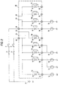
Fig. 2 is a block diagram of the vehicle-mounted electrical
component according to the first embodiment of the invention
showing a state of being applied to the car in accordance with
the second specifications;
Fig. 3 is a perspective view of the vehicle-mounted
electrical component according to the first embodiment of the
invention;
Fig. 4 is a plan view of the vehicle-mounted electrical
component according to the first embodiment of the invention;
Fig. 5 is a perspective view showing an action in which
the short-circuit member is being fitted to the terminal;
Fig. 6 is a perspective view showing a state in which
the short-circuit member is fitted to the terminal;
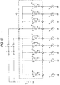
Fig. 7 is a block diagram of the vehicle-mounted electrical
component according to the second embodiment of the invention
showing a state of being applied to the car in accordance with
the first specifications;
Fig. 8 is a block diagram of the vehicle-mounted electrical
component according to the second embodiment of the invention
showing a state of being applied to the car in accordance with
the second specifications;
Fig. 9 is a perspective view of the vehicle-mounted
electrical component according to the second embodiment of the
invention;
Fig. 10 is a plan view of the vehicle-mounted electrical
component according to the second embodiment of the invention;
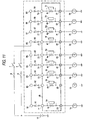
Fig. 11 is a block diagram of the vehicle-mounted
electrical component according to the third embodiment of the
invention showing a state of being applied to the car in
accordance with the first specifications;
Fig. 12 is a block diagram of the vehicle-mounted
electrical component according to the third embodiment of the
invention showing a state of being applied to the car in
accordance with the second specifications;
Fig. 13 is a perspective view of the vehicle-mounted
electrical component according to the third embodiment of the
invention;
Fig. 14 is a plan view of the vehicle-mounted electrical
component according to the third embodiment of the invention;
Fig. 15 is a block diagram showing the vehicle-mounted
electrical component according to the related example 1; and
Fig. 16 is a block diagram showing the vehicle-mounted
electrical component according to the related example 2.
DETAILED DESCRIPTION OF THE PREFERRED EMBODIMENTS
Now, a description will be given in more detail of preferred
embodiments of the invention with reference to the accompanying
drawings.
(First Embodiment)
<Structure>
Fig. 1 is a block diagram showing a circuit in the first
state in which the junction block JB as a vehicle-mounted
electrical component according to the first embodiment of the
present invention is connected to a plurality of loads 1a, 2a-2d,
3a-3d such as a vehicle-mounted lamp or the like, Fig. 2 is
a block diagram showing a circuit in the second state in which
said junction block JB is connected to a plurality of load 1a,
1b, 2a, 2b, 3a, and 3b, Fig. 3 is a perspective view of the
junction block JB, and Fig. 4 is a plan view of the same.
Identical numerals and signs designate the components having
the same functions as related examples. Especially as regards
the arrangement of the loads 1a, 1b, 2a-2d, and 3a-3d, Fig.
1 corresponds to the related example 1, and Fig. 2 corresponds
to the related example 2.
As shown in Figs. 1 and 2, the junction block JB as a
vehicle-mounted electrical component detects a break in the
lamp, if any, by detecting voltage drop at any of the detector
resistances 4a-4i connected to the loads 1a, (1b), 2a-2d, 3a-3d
respectively in series when a plurality of loads 1a, (1b), 2a-2d,
3a-3d are energized. Especially, as shown in Fig. 2,
short-circuit members 11, 12 (Fig. 5 and Fig. 6) formed of a
electrically conductive material such as metal can be detachably
mounted for connecting and disconnecting the detector
resistances that can be redundant depending on the arrangement
of the loads 1a, 1b, 2a, 2b, 3a, and 3b of the vehicle (hereinafter
referred to as "potentially redundant resistance") and the
corresponding voltage detectors 5e, 5h and 5i to the power source
10.
On the upper surface of the main body 13 of the junction
block JB, as shown in Fig. 4, there are formed a first male
potentially redundant resistance connecting terminal 21
connected in common to one end of the potentially redundant
resistance 4e and the corresponding voltage detector 5e, a second
male potentially redundant resistance connecting terminal 22
connected in common to one ends of the respective potentially
redundant resistances 4h, 4i and the corresponding voltage
detectors 5h, 5i, two male intermediate connecting terminals
23, 24 connected in common to one end of the respective detector
resistances other than the potentially redundant resistances
4e, 4h, 4i (hereinafter referred to as "non-redundant
resistance") 4a-4d, 4f, and 4g and the corresponding voltage
detectors 5a-5d, 5f, and 5g respectively and arranged adj acently
in parallel with and spaced from two potentially redundant
resistance connecting terminals 21, 22 as shown in Fig. 4,
male load connecting terminals 25-33 connected respectively
to the other ends of the detector resistances 4a-4i and
connectable to the loads la, (1b), 2a-2d, 3a-3d respectively,
a first male power source connecting terminal 34 connected in
common to any of non-redundant resistances 4a-4d, the voltage
detectors 5a-5d, and the first intermediate connecting terminal
23 and connectable to the power source 10 via the first switch
6 and the first fuse 8, and a second male power source connecting
terminal 35 connected in common to other non-redundant
resistances 4f, 4g, the voltage detectors 5f, 5g, and the second
intermediate connecting terminal 24 and connectable to the power
source 10 via the second switch 7 and the second fuse 9. As
shown in Fig. 3, the potentially redundant resistance connecting
terminals 21, 22 and the intermediate connecting terminals 23,
24 are arranged upright in the recess 41 formed on a part of
the upper surface of the main body 13 of the junction block
JB so as to constitute a first terminal group 42, the load
connecting terminals 25-33 are arranged upright in the second
recess 43 formed on another part of the upper surface of the
main body 13 of the junction block JB so as to constitute the
second terminal group 44, and the power source connecting
terminals 34, 35 are arranged upright in the third recess 45
formed on still another part of the upper surface of the junction
block together with other reserve terminals 36a-36h so as to
constitute the third terminal group 46.
The short- circuit member 11, 12 is, as shown in Fig. 5
and Fig. 6, a female electrically conductive member of a
prescribed metal strip formed of an electric conductor such
as copper in a rectangular shape provided with a pair of insertion
connecting holes 51, 52 for inserting a first potentially
redundant resistance connecting terminal 21 and the first
intermediate connecting terminal 23,or the second potentially
redundant resistance connecting terminal 22 and the second
intermediate connecting terminal 24 for establishing
electrical connections. The insertion connecting holes 51,
52 are formed vertically through the metal strip in parallel
with respect to each other corresponding to the positions and
the configurations of the potentially redundant resistance
connecting terminals 21, 22 and intermediate connecting
terminals 23, 24.
In Figs. 1 and 2, the reference numerals and signs la,
1b designate high-mount stop lamps with power consumption of
18 watts, the reference numerals and signs 2a-2d designate stop
lamps with power consumption of 21 watts, and the reference
numerals and signs 3a-3d designate the tail lamps 3a-3d with
power consumption of 5 watts respectively. The detector
resistances 4a-4e and the corresponding voltage detectors 5a-5e
are used for detecting a break in the high-mount stop lamps
la, 1b and the stop lamps 2a-2d, and the detector resistances
4f-4i and the corresponding voltage detectors 5f-5i are used
for detecting a break in the tail lamps 3a-3d.
The voltage detector circuit 5a-5i used are the same as
ones shown in the related examples 1 and 2, and constructed
in such a manner that the potential difference generated across
each detector resistance 4a-4i is input as a voltage when each
detector resistances 4a-4i is energized and a prescribed signal
is determined by the external determination apparatus, not shown,
with the voltage as a power source. More specifically, a low
voltage output is produced by the use of the voltage drop at
each detector resistance 4a-4i while each detector resistance
4a-4i is being energized, and high voltage output is produced
to the external alarm apparatus or the like, not shown, by
maintaining the voltage level of the power source 10 when each
detector resistance 4a-4i is not energized.
<Operation>
How to use the junction block (vehicle-mounted electrical
components) in the construction described above will now be
described.
| Pin | Vehicle A | Vehicle B | Vehicle C |
| 21-23 | Short-circuit | Open | Open |
| 22-24 | Short-circuit | Open | Short-circuit |
As shown in Fig. 1, in the case of an automotive vehicle
having a high-mount stop lamp la, four stop lamps 2a-2d, and
four tail lamps 3a-3d (Vehicle A in Table 2), a high-mount stop
lamp la is connected to the first load connection terminal 25,
a stop lamps 2a-2d are connected to the second to fifth load
connecting terminals 26-29, and tail lamps 3a-3d are connected
to the sixth to ninth load connection terminals 30-33
respectively, and the power source 10 is connected to the first
power source connection terminal 34 via the first switch 6 and
the first fuse 8, and the power source 10 is connected to the
second power source connection terminal 35 via the second switch
7 and the second fuse 9.
As in the column "Vehicle A" of Table 2, by inserting
the first potentially redundant resistance connecting terminal
21 and the first intermediate connecting terminal 23 into the
insertion connecting holes 51, 52 of the first short-circuit
member 11, the connecting terminals 21, 23 are electrically
short-circuited with respect to each other via the first
short-circuit member 11.
Therefore, the potentially redundant resistances 4e, 4h,
4i and the corresponding voltage detectors 5e, 5h, 5i are
connected to the power source via the potentially redundant
resistance connecting terminals 21, 22, the intermediate
connecting terminals 23, 24, the power source connecting
terminals 34, 35, the switches 6, 7, and the fuses 8, 9.
In this state, the power source is supplied to the junction
block JB by closing the switches 6, 7 and a driving current
is supplied to each load la, 2a-2d, 3a-3d via the junction block
JB. Then, a break in the lamp is detected by detecting voltage
drop at the detector resistances 4a-4i connected in series with
the loads la, 2a-2d, 3a-3d respectively by means of the voltage
detectors 5a-5i.
Specifically, when the loads la, 2a-2d, 3a-3d are not
broken, the loads la, 2a-2d, 3a-3d are energized via the detector
resistances 4a-4i of the junction bock JB, and a low voltage
output is supplied from each voltage detector 5a-5i by the use
of voltage drop at each detector resistance 4a-4i.
On the other hand, when any one of the loads 1a, 2a-2d,
3a-3d is broken, the corresponding detector resistance 4a-4i
is not energized, and the voltage level at the node between
that detector resistance 4a-4i and the broken load 1a, 2a-ed,
3a-3d can be maintained at the voltage level of the power source
10. Therefore, after the voltage detector 5a-5i detected a
break in the load, a high voltage is output to the external
alarm apparatus or the like, not shown, whereby the alarm
apparatus makes an alarm, for example, to notify that any one
or more of the loads 1a, 2a-2d, 3a-3d are broken.
In the junction block (vehicle-mounted electrical
components), in the case of a vehicle having two high- mount
stop lamps 1a, 1b and two stop lamps 2a, 2b, and two tail lamps
3a, 3b (Vehicle B in Table 2) as shown in Fig. 2, one of high-mount
stop lamps la is connected to the first load connecting terminal
25, the stop lamps 2a, 2b are connected to the second and third
load connecting terminals 26, 27, and the tail lamps 3a, 3b
are connected to the sixth and seventh load connecting terminal
30, 31 respectively. The other high-mount stop lamp 1b is
connected to the fourth load connecting terminal 28. No load
is connected to the fifth, eighth, and ninth load connecting
terminals 29, 32, 33. The power source 10 is connected to the
first power source connecting terminal 34 via the first switch
6 and the first fuse 8, and the power source 10 is connected
to the second power source connecting terminal 35 via the second
switch 7 and the second fuse 9.
As shown in the column of "Vehicle B" in Table 2, the
potentially redundant connecting terminals 21, 22 and the
intermediate connecting terminals 23, 24 are not fitted with
the short- circuit members 11, 12 and left opened.
Therefore, a voltage from the power source 10 is not
supplied to the potentially redundant resistances 4e, 4h, 4i
and the corresponding voltage detectors 53, 5h, 5i, whereby
the state in which output from the voltage detecting circuits
5e, 5h, 5i is not supplied to the external alarm apparatus or
the like at all is maintained.
In this state, the power is supplied to the junction block
JB by closing the switches 6, 7, and a driving current is supplied
to the loads 1a, 1b, 2a, 2b, 3a, 3b via the junction block JB.
Then a break in the load 1a, 1b, 2a, 2b, 3a, 3b, if any, is
detected by detecting voltage drop at the detector resistances
4a-4d, 4f, 4g connected in series to the loads 1a, 1b, 2a, 2b,
3a, 3b respectively by the voltage detectors 5a-5d.
Specifically, when the respective loads 1a, 1b, 2a, 2b, 3a,
3b are not broken, a current is supplied to the respective loads
1a, 1b, 2a, 2b, 3a, 3b through the detector resistances 4a-4d,
f, 4g of the junction block JB, and a low voltage output is
produced at the voltage detectors 5a-5d, 5f, 5g by the use of
voltage drop at the detector resistances 4a-4d, 4f, 4g. On
the other hand, when any one of the loads 1a, 1b, 2a, 2b, 3a,
3b is broken, the corresponding detector resistance 4a-4d, 4f,
4g is not energized and thus the voltage level at the node between
the detector resistance 4a-4d, 4f, 4g and the broken load 1a,
1b, 2a, 2b, 3a, 3b is maintained at the voltage level of the
power source 10. Therefore, after the voltage detector 5a-5d,
5f, 5g detected it, a high voltage output is supplied to the
external alarm apparatus or the like, not shown, whereby the
alarm apparatus makes an alarm, for example, to notify that
the any one or more of the loads 1a, 1b, 2a, 2b, 3a, 3b are
broken.
As regards the potential redundant resistances 4e, 4h,
and 4i and the corresponding voltage detectors 5e, 5h, and 5i
to which the loads are not connected, a current from the power
source 10 is not supplied because the short- circuit members
11, 12 are omitted, and thus no signal is transmitted to the
external alarm apparatus. Therefore, as shown in the related
example 2 shown in Fig. 16, a false detection of a break and
an output thereof by the voltage detectors 5e, 5h, 5i due to
the fact that no load is connected is prevented, and output
of an alarm by a prescribed alarm apparatus (not shown) is also
prevented. In other words, a single junction block JB can be
used in common for various car models having different
specifications and for specifications of the limited-edition
car, and thus identification of the junction blocks by colors
of the case or by bar codes, which is required when they are
classified by product number, is not necessary. Therefore,
administrative costs may be reduced since the product number
control, mounting program in the manufacturing process, and
the inspection items for the inspection program are required
only for a single kind of junction block.
As for vehicles with other specifications (corresponds
to another example in Table 1) as Vehicle C in Table 2, it is
also possible to short circuit only between the terminals 21
and 23 by the first short-circuit member 11 and to open between
the terminals 22 and 24. In this case, two high- mount stop
lamps 1a, 1b and two stop lamps 2a, 2b are connected as shown
in Fig. 2 and four tail lamps 3a-3d are connected to the load
connecting terminals 30-33 respectively.
As shown in Fig. 3 and Fig. 4, since the terminals 21-24
(first terminal group 42) for detachably connecting the
short- circuit members 11, 12 is provided upright in the first
recess 41 of the upper surface of the main body 13 of the junction
block JB, the short- circuit members 11, 12 can be attached to
or detached from the terminals 21-24 (first terminal group 42)
in the first recess 41 from outside of the junction block JB
according to the arrangement of the loads, and thus the
vehicle-mounted electrical components (a junction block JB)
with high operability and compatibility may be provided.
In this embodiment, though the terminals 21-24 are formed
as male terminals and the short- circuit members 11, 12 are formed
as male conductive member, so that they can be fitted together,
it is also possible, as a matter of course, to form the terminals
21-24 as female type terminals and the short- circuit members
11, 12 as male conductive members so that they can be fitted
together.
(Second Embodiment)
<Structure>
Fig. 7 is a block diagram of a circuit showing a first
state in which the junction block JB as a vehicle-mounted
component according to the second embodiment of the invention
is connected to a plurality of loads 1a, 2a-2d, 3a-3d such as
a vehicle-mounted lamp or the like, Fig. 8 is a block diagram
of the circuit in a second state in which the junction block
JB is connected to a plurality of loads 1a, 1b, 2a, 2b, 3a,
3b, Fig. 9 is a perspective view of the junction block JB, and
Fig. 10 is a plan view of the same. Identical reference numerals
and signs designate identical components having the same
functions as the first embodiment from Fig. 7 through Fig. 10.
The vehicle-mounted electrical component of this
embodiment is constructed in such a manner that, as shown in
Fig. 7, the fuses 61-69 being interposed between the
vehicle-mounted electrical component and the power source 10
are detachably connectable at the nodes between the detector
resistances 4a-4i and the voltage detectors 5a-5i. When each
fuse 61-69 is connected, a driving current supplied from the
power source 10 through the fuse 8, 9 and switch 6, 7 is supplied
to each detector resistance 4a-4i via each fuse 61-69. On the
other hand, when any one of the fuses 61-69 is removed, a driving
current supplied from the power source 10 via the fuses 8, 9
and the switches 6, 7 is prevented from being supplied to the
detector resistance 4a-4i and the voltage detector 5a-5i
corresponding to the removed fuse 61-69.
These fuses 61-69 are constructed in such a manner that
two pins 60a, 60b projecting downwardly from the lower ends
of the fuses 61-69 are inserted into the female terminals 71-89
formed in the recesses 55a, 55b on the upper surface of the
main body 13 of the junction block JB from the outside so that
the detector resistances 4a-4i and the voltage detectors 5a-5i
in the junction block JB shown in Fig. 7 and Fig. 8 are connected
to the power source 10.
The terminals 71-79 are connected to the nodes of the
detector resistances 4a-4i and the voltage detectors 5a-5i on
the side of the power source 10. The terminals 81-89 are
connected in common to the first power source connecting terminal
34, and the terminals 86-89 are connected in common to the second
power source connecting terminal 35.
As shown in Fig. 10, the terminal 71 and the terminal
81 are connected via the fuse 61 by placing those terminals
adjacently in parallel with respect to each other and inserting
both pins 60a, 60b of a single fuse 61 simultaneously into those
terminals. Likewise, the terminals 72 and 82 are connected
via the fuse 62 by placing those terminals 72 and 82 adjacently
in parallel with respect to each other and inserting both pins
60a, 60b of a single fuse 62 simultaneously into those terminals .
Again, the terminals 73-79 and the terminals 83-89 are connected
respectively via the respective fuses 63-69 by placing the those
terminals 73-79 and 83-89 adjacently with in parallel with
respect to each other and inserting both pins 60a and 60b of
the respective fuses 63-69 simultaneously into those terminals.
The reference numerals and signs 55, and 55d in Figs.
9 and 10 designate the recesses, and the reference numerals
56a-56d designate the terminal group respectively.
Since other constructions are the same as the first
embodiment, the description will be omitted.
<Operation>
The operation of the vehicle-mounted electrical component
having a structure described above will now be described.
| Fuse | Vehicle A | Vehicle B | Vehicle C | |
| 64 | Present | Not prevent | Not present |
| 68 | Present | Not present | Present | |
| 69 | Present | Not present | Present |
As shown in Fig. 7, in the case of an automotive vehicle
having one high-mount stop lamp 1a, four stop lamps 2a-2d, and
four tail lamps 3a-3d (Vehicle A in Table 3), the high-mount
stop lamp 1a is connected to the first load connecting terminal
25, the stop lamps 2a-2d are connected to the second to fifth
load connecting terminals 26-29, and the tail lamps 3a-3d are
connected to the sixth to ninth load connecting terminals 30-33
respectively, the power source 10 is connected to the first
power source connecting terminal 34 via the first switch 6 and
the first fuse 8, and the power source 10 is connected to the
second power source connecting terminal 35 via the second switch
7 and the second fuse 9.
Since all the detector resistances 4a-4i and the voltage
detectors 5a-5i have the loads la, 2a-2d, 3a-3d connected there to,
the fuses 61-69 are connected to all the terminals 71-89 from
the outside as shown in Fig. 9. Especially, the fuses 64, 68,
69 are fitted to the terminals 74, 84, the terminals 78, 88,
and the terminals 79, 89 as shown in the column of "Vehicle
A" in Table 3, and the adjacent pairs of terminals 74 and 84,
78 and 88, 79 and 89 are electrically shorted.
Accordingly, the potential redundant resistances 4d, 4h,
4i and the corresponding voltage detectors 5d, 5h, 5i are
connected to the power source 10 via the terminals (potential
redundant resistance connecting terminals) 74, 78, 79, the fuses
64, 68, 69, the terminals (intermediate connecting terminals)
84, 88, 89, the power source connecting terminals 34, 35, the
switches 6, 7, and the fuses 8, 9.
In this state, the power source is supplied to the junction
block JB by closing the switches 6, 7 and a driving current
is supplied to each load 1a, 2a-2d, 3a-3d via the junction block
JB. Then, a break in the lamp is detected by detecting voltage
drop at the detector resistances 4a-4i connected respectively
in series to the loads 1a, 2a-2d, 3a-3d by means of the voltage
detectors 5a-5i.
In the junction block (vehicle-mounted electrical
components) JB, in the case of a vehicle having two high- mount
stop lamps 1a, 1b and two stop lamps 2a, 2b, and two tail lamps
3a, 3b (Vehicle B in Table 3) as shown in Fig. 8, one of high-mount
stop lamps 1a is connected to the first load connecting terminal
25, the stop lamps 2a, 2b are connected to the second and third
load connecting terminals 26, 27, and the tail lamps 3a, 3b
are connected to the sixth and seventh load connecting terminals
30, 31 respectively. The other high-mount stop lamp 1b is
connected to the fifth load connecting terminal 29. No load
is connected to the fourth, eighth, and ninth load connecting
terminals 28, 32, 33. The power source 10 is connected to the
first power source connecting terminal 34 via the first switch
6 and the first fuse 8, and the power source 10 is connected
to the second power source connecting terminal 35 via the second
switch 7 and the second fuse 9.
Then the fuses 61-63, 65-67 are connected to the terminals
71-73, 75-77, 81-83, 85-87 respectively. At this time, the
terminals 74, 84, the terminals 78, 88, and the terminals 79,
89 are not fitted with the fuse as the column of "Vehicle B"
in Table 3.
Therefore, the potentially redundant resistances 4d, 4h,
4i and the corresponding voltage detectors 5d, 5h, 5i are not
supplied with a current from the power source 10 and no signal
output is supplied to the exterior alarm apparatus or the like
because the fuses 64, 68, 69 are omitted. Therefore, it is
prevented that each voltage detector 5d, 5h, 5i detects a break
of the lamp in error resulting from no load being connected,
produces an output to notify the occurrence of said break, and
thus makes an alarm by the prescribed alarm apparatus (not shown)
as in the case of the related example 2 shown in Fig. 16.
As regards the automotive vehicles of other
specifications as the Vehicle C in Table 3 for example, it is
also possible to connect fuses 68, 69 between the terminals
78, 88 and the terminals 79, 89 respectively so as to cause
a short-circuit therebetween, and to open between the terminals
74 and 84.
As in Figs. 9 and 10, since the terminals 71-89 are formed
in the recesses 55a, 55b on the upper surface of the main body
13 of the junction block JB so that the fuses 61-69 are detachably
connected thereto, the fuses 61-69 can be connected from the
outside of the junction block JB according to the arrangement
of the loads, and thus a vehicle-mounted electrical components
(junction block JB) with high operability and compatibility
may be provided.
Instead of the fuses 61-69 in Fig. 7, the short-circuit
member as shown in the first embodiment may be used as a matter
of course to obtain the same effect.
(Third Embodiment)
<Structure>
Fig. 11 is a block diagram of the circuit showing a first
state in which a junction block JB as a vehicle-mounted
electrical component according to the third embodiment of the
invention is connected to a plurality of loads 1a, 2a-2d, 3a-3d
such as the vehicle-mounted lamp or the like, Fig. 12 is a block
diagram of the circuit showing a second state in which a junction
block JB is connected to a plurality of loads 1a, 1b, 2a, 2b,
3a, 3b, Fig. 13 is a perspective view of the junction block
JB, and Fig. 14 is a plan view thereof. Identical reference
numbers and signs designate components having the same functions
as in the second embodiment from Figs. 11 to 14.
In the vehicle-mounted electrical component of this
embodiment, as shown in Fig. 11, individual slidable switches
91-99 is interposed between the vehicle-mounted electrical
component and the power source 10 at the nodes between the
respective detector resistances 4a-4i and the respective
voltage detectors 5a-5i so as to be opened and closed freely.
When each switch 91-99 is closed (turned on), a driving current
supplied from the power source 10 through the fuse 8, 9 and
the switch 6, 7 is supplied to each detector resistance 4a-4i
and each voltage detector 5a-5i via each switch 91-99. On the
other hand, when any one of the switches 91-99 is opened (turned
off), a driving current supplied from the power source 10 via
the fuse 8, 9 and the switch 6, 7 is prevented from being supplied
to the detector resistances 4a-4i and the voltage detectors
5a-5i corresponding to the opened switches 91-99.
These switches 91-99 are interposed between the terminals
71-79 on the side of the detector resistances 4a-4i and the
voltage detectors 5a-5i and the terminals 81-89 on the side
of the power source 10 respectively.
As shown in Figs . 13 and 14, the switches 91-99 are mounted
on the upper surface of the main body 13 of the junction block
JB, and can be switched between opened state and closed state
(ON-OFF switching) respectively from the outside of the junction
block JB.
Since other structures are the same as the second
embodiment, the description will be omitted.
<Operation>
The operation of the vehicle-mounted electrical component
having a structure as described above will now be described.
| Switch | Vehicle A | Vehicle B | Vehicle C | |
| 94 | On | Off | Off | |
| 98 | On | Off | On |
| 99 | On | Off | On |
As shown in Fig. 11, in the case of an automotive vehicle
having one high-mount stop lamp 1a, four stop lamps 2a-2d, and
four tail lamps 3a-3d (Vehicle A in Table 3), the high-mount
stop lamp la is connected to the first load connecting terminal
25, the stop lamps 2a-2d are connected to the second to fifth
load connecting terminals 26-29, and the tail lamps 3a-3d are
connected to the sixth to ninth load connecting terminals 30-33
respectively, the power source 10 is connected to the first
power source connecting terminal 34 via the first switch 6 and
the first fuse 8, and the power source 10 is connected to the
second power source connecting terminal 35 via the second switch
7 and the second fuse 9.
Since all the detector resistances 4a-4i and the voltage
detectors 5a-5i have the loads 1a, 2a-2d, 3a-3d connected there to,
all the switches 91-99 connected to the terminals 71-89 are
switched to the closed state (ON-state) from the outside as
shown in Fig. 11. Especially, the switches 94, 98, 99 interposed
respectively between the terminals 74 and 84, the terminals
78 and 88, and the terminals 79 and 89 are also switched into
the closed-state respectively as the Vehicle A in Table 4 as
in the case of the switches 91-93 and 95-97.
Accordingly, the potentially redundant resistances 4d,
4h, 4i and the corresponding voltage detecting circuit 5d, 5h,
5i are connected to the power source 10 via the terminals
(potentially redundant resistance connecting terminals) 74,
78, 79, the switches 94, 98, 99, the terminals (intermediate
connecting terminals) 84, 88, 89, the power source connecting
terminals 34, 35, the switches 6, 7 and the fuses 8, 9.
In this state, the power source is supplied to the junction
block JB by closing the switches 6, 7 and a driving current
is supplied to each load 1a, 2a-2d, 3a-3d via the junction block
JB. Then, a break in the lamp is detected by detecting voltage
drop at the detector resistances 4a-4i connected respectively
in series with each loads 1a, 2a-2d, 3a-3d by means of the voltage
detectors 5a-5i.
In the junction block (vehicle-mounted electrical
components) JB, in the case of a vehicle having two high- mount
stop lamps 1a, 1b and two stop lamps 2a, 2b, and two tail lamps
3a, 3b (Vehicle B in Table 4) as shown in Fig. 8, one of high-mount
stop lamps la is connected to the first load connecting terminal
25, the stop lamps 2a, 2b are connected to the second and third
load connecting terminals 26, 27, and the tail lamps 3a, 3b
are connected to the sixth and seventh load connecting terminal
30, 31 respectively. The other high-mount stop lamp 1b is
connected to the fifth load connecting terminal 29. No load
is connected to the fourth, eighth, and ninth load connecting
terminals 28, 32, 33. The power source 10 is connected to the
first power source connecting terminal 34 via the first switch
6 and the first fuse 8, and the power source 10 is connected
to the second power source connecting terminal 35 via the second
switch 7 and the second fuse 9.
Then only the switches 91-93, 95-97 are switched into
the closed state (ON-state). In this case, the switches 94,
98, and 99 are left opened (OFF-state) as the column of "Vehicle
B" in Table 4.
Therefore, as regards the potentially redundant
resistances 4d, 4h, 4i and the corresponding voltage detectors
5d, 5h, 5i, a current from the power source 10 is not supplied
and no signal is output to the exterior alarm apparatus or the
like because the switches 94, 98, 99 are in the OFF-state.
Therefore, it is prevented that each voltage detector 5d, 5h,
5i detects a break of the lamp in error resulting from no load
being connected, produces an output to notify the occurrence
of said break, and thus makes an alarm by the prescribed alarm
apparatus (not shown) as in the case of the related example
2 shown in Fig. 16.
As regards the automotive vehicles of other
specifications as the Vehicle C in Table 4 for example, it is
also possible to turn the switches 98, 99 in ON-state so as
to cause a short-circuit between the terminals 78 and 88, and
the terminals 79 and 89, and to turn the switch 94 OFF.
As in Figs . 13 and 14, since the switches 91-99 are mounted
on the upper surface of the main body 13 of the junction block
JB so as to be able to switch ON and OFF from the outside, a
vehicle-mounted electrical components (junction block JB) with
high operability and compatibility may be provided.
Instead of the short- circuit member 11, 12 in Fig. 1 as
described in conjunction with the first embodiment, the switch
as shown in the third embodiment may be used as a matter of
course to obtain the same effect.
According to the invention according to the first to fourth
aspects, as regards the potentially redundant resistance and
the switching of short-circuit/disconnection between the
respective potentially redundant resistance connecting
terminals and the intermediate connecting terminals may be
easily performed by attaching/detaching the short-circuit
member as stated in conjunction with the second aspect or the
fuse as stated in conjunction with the third aspect to/from
the potentially redundant connecting terminals and the
intermediate connecting terminals on the external surface of
the main body or by opening/closing the switch as stated in
conjunction with the fourth aspect. As a consequent, when no
load is connected to the potentially redundant resistance and
the intermediate connecting terminal, preventing supply of a
current from the power source to the voltage detector by
disconnecting between the potentially redundant resistance
terminal and the intermediate connecting terminal respectively
may prohibit all the signals from being supplied from the voltage
detector to the exterior alarm apparatus or the like, and thereby
preventing the voltage detector from detecting a break in the
load in error and producing an output to notify that a break
is occurred. Therefore, in other words, a single
vehicle-mounted electrical component can be shared for various
car models having different specifications or specifications
for the limited-edition car, whereby administrative costs may
be reduced since the product number control, mounting program
in the manufacturing process, and the inspection items for the
inspection program are required only for a single kind of
junction block.
In addition, since the switching of
short-circuit/disconnection of the connecting member such as
the short-circuit member, the fuse, or the switch may be
performed outside the main body, a vehicle-mounted electrical
component with high operability and compatibility may be
provided.