EP1125772A2 - Tyre inflation station and method to inflate tyres - Google Patents
Tyre inflation station and method to inflate tyres Download PDFInfo
- Publication number
- EP1125772A2 EP1125772A2 EP01103043A EP01103043A EP1125772A2 EP 1125772 A2 EP1125772 A2 EP 1125772A2 EP 01103043 A EP01103043 A EP 01103043A EP 01103043 A EP01103043 A EP 01103043A EP 1125772 A2 EP1125772 A2 EP 1125772A2
- Authority
- EP
- European Patent Office
- Prior art keywords
- tire
- wheel
- filling
- transport
- filling station
- Prior art date
- Legal status (The legal status is an assumption and is not a legal conclusion. Google has not performed a legal analysis and makes no representation as to the accuracy of the status listed.)
- Granted
Links
- 238000000034 method Methods 0.000 title claims description 10
- 238000007789 sealing Methods 0.000 claims abstract description 55
- 238000003860 storage Methods 0.000 claims description 11
- 239000000945 filler Substances 0.000 claims description 2
- 238000005429 filling process Methods 0.000 description 6
- 238000010276 construction Methods 0.000 description 3
- 239000012530 fluid Substances 0.000 description 2
- 238000004519 manufacturing process Methods 0.000 description 2
- 230000000712 assembly Effects 0.000 description 1
- 238000000429 assembly Methods 0.000 description 1
- 230000015572 biosynthetic process Effects 0.000 description 1
- 238000006073 displacement reaction Methods 0.000 description 1
- 238000011144 upstream manufacturing Methods 0.000 description 1
Images


Classifications
-
- B—PERFORMING OPERATIONS; TRANSPORTING
- B60—VEHICLES IN GENERAL
- B60C—VEHICLE TYRES; TYRE INFLATION; TYRE CHANGING; CONNECTING VALVES TO INFLATABLE ELASTIC BODIES IN GENERAL; DEVICES OR ARRANGEMENTS RELATED TO TYRES
- B60C25/00—Apparatus or tools adapted for mounting, removing or inspecting tyres
- B60C25/14—Apparatus or tools for spreading or locating tyre beads
- B60C25/145—Apparatus or tools for spreading or locating tyre beads for locating provisionally the beads of tubeless tyres against the sealing surfaces of the rims, e.g. air filling bell
-
- B—PERFORMING OPERATIONS; TRANSPORTING
- B60—VEHICLES IN GENERAL
- B60C—VEHICLE TYRES; TYRE INFLATION; TYRE CHANGING; CONNECTING VALVES TO INFLATABLE ELASTIC BODIES IN GENERAL; DEVICES OR ARRANGEMENTS RELATED TO TYRES
- B60C25/00—Apparatus or tools adapted for mounting, removing or inspecting tyres
- B60C25/01—Apparatus or tools adapted for mounting, removing or inspecting tyres for removing tyres from or mounting tyres on wheels
- B60C25/05—Machines
- B60C25/132—Machines for removing and mounting tyres
- B60C25/135—Machines for removing and mounting tyres having a tyre support or a tool, movable along wheel axis
-
- Y—GENERAL TAGGING OF NEW TECHNOLOGICAL DEVELOPMENTS; GENERAL TAGGING OF CROSS-SECTIONAL TECHNOLOGIES SPANNING OVER SEVERAL SECTIONS OF THE IPC; TECHNICAL SUBJECTS COVERED BY FORMER USPC CROSS-REFERENCE ART COLLECTIONS [XRACs] AND DIGESTS
- Y10—TECHNICAL SUBJECTS COVERED BY FORMER USPC
- Y10T—TECHNICAL SUBJECTS COVERED BY FORMER US CLASSIFICATION
- Y10T137/00—Fluid handling
- Y10T137/3584—Inflatable article [e.g., tire filling chuck and/or stem]
Definitions
- the invention relates to a tire inflation station consisting of a wheel rim and a wheel / tire assembly mounted on the wheel rim a transport device can be fed, with a tire filling bell, with a Side surface of the tire interacts with one with the opposite Side surface of the wheel / tire assembly cooperating bearing and sealing device and with a device by means of the wheel / tire arrangement and transport device are movable relative to one another transversely to the transport plane.
- wheel rims and tires are different Storage locations by means of suitable conveyors on a tire assembly line fed, where the tire is mounted on the wheel rim and then the desired tire pressure is created using compressed air filling. Subsequently the wheel thus completed is e.g. checked for running properties or imbalance and usually still balanced. The finished wheel is now off the tire assembly line the assembly line for the complete vehicle.
- a tire inflation station of the type mentioned is known from US Pat. No. 4,947,919.
- the tire mounting and inflation system according to this publication essentially shows an assembly station, a conveyor and a tire filling station on.
- the tire In the assembly station, the tire is mounted on the wheel rim and in a depressurized state Condition fed via the conveyor to the tire inflation station.
- the conveyor consists of two chains on which the wheel / tire arrangement with the Tire side surfaces rests.
- the conveyor is lowered in the tire filling station, so that the wheel / tire assembly with side surfaces on a platen lies on. Above the other top of the wheel / tire assembly as shown in FIG.
- a tire inflation bell is arranged, which is lowered for the tire inflation process and with its edge pushes the tire sidewall away from the rim, so that an annular Space is created between the tire sidewall and the wheel rim through which the compressed air is filled the tire.
- the compressed air flows from the one arranged in the platen Compressed air source via the sealed rim interior into the filling bell and from there over the annulus to the inside of the tire and finally moves it Tire sidewall with closure of the annulus in systems on the rim.
- This Known tire filling station is not suitable for tire assembly lines on which Wheels of very different tire and / or rim sizes are to be fitted because of the diameter of the platen limited by the conveyor or by the diameter of the filling bell rim or tire larger diameter cannot be easily assembled or filled.
- the invention is therefore based on the object of a device and a method to create for the tire inflation, which for different wheel models or Wheel sizes can also be used in mixed operation in automated systems.
- the invention is based on the knowledge that the The scope of tire inflation equipment is to be expanded in that sealing ringless filling devices the dimensions of the bearing and sealing surface for the Wheel / tire arrangement or the filling bell dimensions regardless of the dimensions the transport device can be selected.
- This is according to the invention provided to design the sealing surface and / or the filling bell in several parts, so that the diameter regardless of the design and size of the Transport device will be.
- the tire is inflated without a seal it also results in With regard to known pallet transport systems in which each wheel / tire arrangement is assigned its own transport range, a serious cost and Cycle time savings.
- the transport device two means of transport arranged on both sides of the wheel center for support the wheel / tire assembly and that the platen at least one has central, arranged between the means of transport and at least a part that can be sealed against the central part.
- a compact embodiment of the invention results from the fact that the side part that can be put on from a position between the means of transport into the system position is movable, since here the displacement or pivoting transversely to the direction of transport done from the inside out.
- An embodiment according to the invention in which preferably two further parts are arranged laterally next to the means of transport and transverse to the direction of transport are movable into the contact position has the advantage that only two sealing joints between the parts of the bearing and sealing device are present and a simple one Moving in a plane takes place.
- a further development of the invention in which also seals against the central part adjacent parts on a frame element supporting the central part Tire inflation station are supported has the advantage that after moving the parts in no-load condition, which takes place without complex guide elements during the filling process parts under force are supported on a stable support structure are. This enables a lighter construction.
- the Tire inflation rings arranged concentrically and movable against each other in the axial direction are. Such an arrangement allows a nested one Construction of the filling rings and thus a compact design with a wide working range.
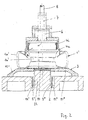
- the tire inflation station shown in FIG. 1 becomes a wheel / tire arrangement 1 a transport device 2 is fed and on a storage and sealing device 3 stored.
- the tire filling process is carried out as a compressed air filling using the number 4 Tire bell.
- a tire fitting station is located upstream of the tire inflation station, in which the tire 1a is applied to the wheel rim 1b in a known manner and then as a wheel / tire assembly 1 in a depressurized state to the tire filling station transported and transported from there after inflation.
- the stations can each have a machine frame as individual modules, but it can a common machine frame is also provided for different stations his.
- the tire inflation station is shown in FIG. 1 and also in FIG. 3 as a half section in each case two different work phases. In the right half of the illustration the transport phase is shown, while in the left half of the illustration the tire inflation or inflation phase is shown.
- the transport device has two that run in the horizontal transport plane spaced apart transport means 5 ', 5 ", for example as transport chains or belts are formed and mounted on the machine frame 9.
- the means of transport 5 ', 5 " run on both sides of the axis of rotation of the wheel / tire arrangement 1, this axis being vertical to the transport plane. In other words, that the wheel / tire assembly 1 is transported and treated horizontally.
- the wheel / tire arrangement 1 is diametrically opposed Rim side surfaces on the two transport means 5 ', 5 ". It can also be provided that the wheel / tire assembly 1 with diametrically opposite Tire side surfaces rests on the two transport means 5 ', 5 "
- the wheel / tire arrangement 1 is raised transported to the tire inflation station until it is centered under the tire inflation bell 4 lies and then by lowering the transport device 2 on the central plate-shaped Part 10 of the bearing and sealing device 3 applied.
- the central one plate-shaped part 10 is on a columnar part 22 of the machine frame 9 supported.
- the transport device 2 or the two transport means 5 ', 5 " until fully immersed in receiving spaces 11 ', 11 "of the machine frame 9 lowered.
- the bearing and sealing device 3 is constructed in several parts and has the central one plate-shaped part 10, which is supported on the machine frame 9 and the Extension in the direction of transport is greater than the diameter of the support surface the largest wheel / tire arrangement to be filled 1. This ensures stable storage given the wheel / tire assembly 1 on the central part 10.
- the warehouse and Sealing device 3 has two further plate-shaped parts 10 ', 10 ", which during the transport phase to both sides of the movement path of the transport device 2 are arranged, as can be seen from the right half of FIG. 1.
- the adjacent parts 10, 10 ', 10 "of the bearing and sealing device 3 are provided with sealing devices, in the embodiment shown in FIG Form of mutually associated projections and depressions. However, it can elastic sealing devices such as sealing cords or the like are also used are arranged in grooves of the parts 10, 10 ', 10 ".
- the two lateral Parts 10 ', 10 ", like the central part 10, are rectangular in plan view and have the same extension along the direction of transport as the central part 10.
- the bearing and sealing device 3 in plan view to form as a circular area; the two side parts 10 ', 10 "are then in Top view in the form of a segment.
- the extension of the bearing and sealing device 3 in the storage plane transverse to the direction of transport is larger than the diameter of the Contact surface of the largest wheel / tire arrangement to be filled. It's in the frame the invention to provide only a lateral part and the central part 10 in the To make the storage level movable.
- the side part is attached to the central part 10 moved transversely to the transport direction and then together with this moved further until the parting line is centered between the means of transport 5 ', 5 ".
- lateral parts 10 ', 10 centrally between the means of transport 5 ', 5 "are provided, which then be moved laterally outwards and to form a flat sealing surface be moved to the storage and sealing level. Also a swivel movement the parts from the central area is within the scope of the invention.
- the tire inflation bell shown in Fig. 1 is formed in several parts and has in illustrated embodiment two axially displaceable tire inflation rings 4a, 4i of different diameters, each with its edge for Tire inflation are brought into contact with the tire sidewall and this tire sidewall push away from the rim 1b so that an annular space 12 between Tire 1a and wheel rim 1b are created, via which the compressed air filling of the tire he follows.
- the tire inflation bell 4 is overall, i.e. with their two tire inflation rings 4a, 4i, for example fluidly movable relative to the wheel / tire arrangement 1.
- the tire bell 4 is out of position during the transport phase (right half of the illustration), in which the edges of the two tire inflation rings 4a, 4i are approximately at the same height, in the tire inflation position lowered (left half of the illustration), with the inner tire filler ring in addition 4i opposite the outer tire inflation ring 4a towards the wheel / tire arrangement 1 is moved.
- the inner tire inflation ring 4i is connected to a piston 6, the fluid operated is displaceable.
- the outer tire inflation ring 4a is concentric with one connected to him arranged housing in which the piston 6 fluid-operated is movable.
- a central bore 7 in this piston 6 is used by a Compressed air source, for example a compressed air tank via a line 8 Compressed air supplied to the interior of the tire bell 4, as is done by the Arrows are indicated in the illustration. However, it can in the compressed air supply the interior of the tire inflation bell 4 also by supplying compressed air from below the sealing surface or on the side of the bell.
- a Compressed air source for example a compressed air tank via a line 8 Compressed air supplied to the interior of the tire bell 4
- the compressed air supplied to the interior of the tire inflation bell 4 also by supplying compressed air from below the sealing surface or on the side of the bell.
- the tire filling position is shown in the left half of FIG. 1; the wheel / tire assembly 1 lies on the bearing and composed of its parts 10, 10 ', 10 " Sealing device 3, the tire side wall sealing the interior which rests on the sealing surface composed of the parts 10, 10 ', 10 ".
- the edge of the inner tire inflation ring 4i has lifted off the tire sidewall.
- About the central Bore 7 is filled with compressed air, the interior of the tire filling bell 4, the tire interior and the sealing surface from the parts 10, 10 ', 10 "of Bearing and sealing device 3 a sealed off from the environment Define space.
- the pressure builds up upper tire sidewall against the force exerted by the inner tire inflation ring 4i while moving the inner tire inflation ring 4i upwards against the rim flange pressed.
- the tire inflation bell 4 then moves into it during transport the wheel / tire assembly 1 provided position, the side parts 10 ', 10 "of Storage and sealing device 3 are moved apart, the transport device 2 raised and the filled wheel, which rests on the transport means 5 ', 5 ", transported further. It is within the scope of the invention to fill the tire with the to design the multi-part tire inflation bell according to the invention as a single machine, which the wheel / tire assemblies manually instead of by means of a transport device fed and removed; the multi-part design of the platen can omitted.
- the tire inflation station shown in FIG. 2 corresponds to the tire inflation station shown in FIG. 1.
- a wheel / tire arrangement 1 'with significantly larger dimensions for filling provided, for example that of an 18 "wheel instead of one Wheel / tire arrangement of a 13 "wheel as in FIG. 1.
- the tire filling position is shown, in the the used because of the larger tire dimensions
- Tire inflation ring 4a larger diameter the side surface of the tire 1a 'under Formation of an annular gap has pushed away from the rim 1b '.
- FIG. 3 shows an embodiment of the invention in two half-sections, in which the transport device 2 for the purpose of storing the Wheel / tire assembly 1 is not lowered for the filling process.
- the wheel / tire assembly 1 is raised until the two plate-shaped Parts 10 ', 10 "of the bearing and sealing device 3 via the movement paths the means of transport 5 ', 5 "are moved away in contact with the central part 10 can.
- the embodiment according to FIG. 3 otherwise the tire inflation station according to FIG. 1.
- the tire inflation station shown in FIG. 4 essentially corresponds to that in FIG. 2 shown tire inflation station. 2, however, is only the central one Part 10 of the bearing and sealing device 3 on the columnar part 22 of the Machine frame 9 supported.
- the two side parts 10 ', 10 "of the bearing and Sealing device 3 are in each case on the outer regions of the machine frame 9 supported.
- the support on the outer regions of the parts 10 'and 10 " is sufficient in many cases, especially since support is also provided via the arrangement the sealing lips between the central part 10 and outer parts 10 'and 10 " is present.
- great force e.g. large compressive forces when filling larger Tire is an additional support for the inner areas of the side parts 10 'and 10 "of the bearing and sealing device 3 advantageous.
- Part 10 of the bearing and sealing device 3 is narrower and the side Parts 10 'and 10 "come with their sealing edges closer to the central axis and are supported in the case of parts 10, 10 ', 10 "which are in sealing contact with one another the columnar part 22 of the machine frame 9.
- the side Parts 10 ', 10 take place in a load-free state without complex guide elements and during the filling process the parts 10 'and 10 "are on a stable support structure, namely the columnar part 22 of the machine frame 9, supported.
- the central part of the storage and sealing device can in a manner not shown have a projection that is in the opposite rim interior extends and fills this to a large extent.
- the lead can be at the central Part can be molded, but it can also be a fitting on the central part be arranged. Such a configuration reduces the filling volume, since a Part of the total space sealed during the filling process is filled by the projection and this volume is not filled with compressed air. Therefore, the dead space i.e. the remaining sealed space not enclosed by the tire is reduced.
- the projection can also be a centering lug for the purpose of centered reception the wheel / tire assembly.
Abstract
Bei einer Reifenfüllstation, der aus einer Radfelge (1b, 1b') und einem auf die Radfelge (1b, 1b') montierten Reifen (1a, 1a') bestehende Rad/Reifenanordnung (1, 1') über eine Transportvorrichtung (2) zuführbar sind und die eine Reifenfüllglocke (4), die mit einer Seitenfläche des Reifens (10, 10') zusammenwirkt, aufweist sowie eine mit der gegenüberliegenden Seitenfläche der Rad/Reifenanordnung (1, 1') zusammenwirkende Lager- und Dichteinrichtung (3), wird vorgeschlagen, die Lager- und Dichtfläche (3) und/oder die Füllglocke (4) mehrteilig zu gestalten, um so die Verwendbarkeit für unterschiedliche Radmodelle bzw. Radgrößen auch im Mixbetrieb auf automatischen Anlagen zu ermöglichen. <IMAGE>In a tire filling station, the wheel / tire arrangement (1, 1 ') consisting of a wheel rim (1b, 1b') and a tire (1a, 1a ') mounted on the wheel rim (1b, 1b') can be fed via a transport device (2) and which has a tire inflation bell (4) which interacts with one side surface of the tire (10, 10 ') and a bearing and sealing device (3) which interacts with the opposite side surface of the wheel / tire arrangement (1, 1') It is proposed to design the bearing and sealing surface (3) and / or the filling bell (4) in several parts, so that the usability for different wheel models or wheel sizes can also be used in mixed operation on automatic systems. <IMAGE>
Description
Die Erfindung bezieht sich auf eine Reifenfüllstation, der aus einer Radfelge und einem auf die Radfelge montierten Reifen bestehende Rad/Reifenanordnungen über eine Transporteinrichtung zuführbar sind, mit einer Reifenfüllglocke, die mit einer Seitenfläche des Reifens zusammenwirkt, mit einer mit der gegenüberliegenden Seitenfläche der Rad/Reifenanordnung zusammenwirkenden Lager- und Dichteinrichtung und mit einer Einrichtung mittels der Rad/Reifenanordnung und Transporteinrichtung quer zur Transportebene relativ zueinander bewegbar sind.The invention relates to a tire inflation station consisting of a wheel rim and a wheel / tire assembly mounted on the wheel rim a transport device can be fed, with a tire filling bell, with a Side surface of the tire interacts with one with the opposite Side surface of the wheel / tire assembly cooperating bearing and sealing device and with a device by means of the wheel / tire arrangement and transport device are movable relative to one another transversely to the transport plane.
Bei der Serienfertigung von Kraftfahrzeugen werden Radfelgen und Reifen von unterschiedlichen Lagerstellen mittels geeigneter Fördereinrichtungen einer Reifenmontagestraße zugeführt, bei der der Reifen auf der Radfelge montiert und danach der gewünschte Reifendruck mittels Druckluftfüllung hergestellt wird. Anschließend wird das so fertiggestellte Rad z.B. auf Laufeigenschaften oder Unwuchten geprüft und in der Regel noch ausgewuchtet. Das fertige Rad wird nun von der Reifenmontagestraße der Montagelinie für das Komplettfahrzeug zugeführt.In the series production of motor vehicles, wheel rims and tires are different Storage locations by means of suitable conveyors on a tire assembly line fed, where the tire is mounted on the wheel rim and then the desired tire pressure is created using compressed air filling. Subsequently the wheel thus completed is e.g. checked for running properties or imbalance and usually still balanced. The finished wheel is now off the tire assembly line the assembly line for the complete vehicle.
Eine Reifenfüllstation der eingangs genannten Art ist aus der US-PS 4,947,919 bekannt. Das Reifenmontier- und füllsystem nach dieser Veröffentlichung weist im wesentlichen eine Montagestation, eine Fördereinrichtung und eine Reifenfüllstation auf. In der Montagestation wird der Reifen auf die Radfelge montiert und in drucklosem Zustand über die Fördereinrichtung der Reifenfüllstation zugeführt. Die Fördereinrichtung besteht aus zwei Ketten, auf denen die Rad/Reifenanordnung mit den Reifenseitenflächen aufliegt. In der Reifenfüllstation wird die Fördereinrichtung abgesenkt, so daß die Rad/Reifenanordnung mit Seitenflächen auf einer Auflageplatte aufliegt. Oberhalb der anderen gemäß Fig. 5 oberen Seite der Rad/Reifenanordnung ist eine Reifenfüllglocke angeordnet, die zum Reifenfüllvorgang abgesenkt wird und mit ihrem Rand die Reifenseitenwand von der Felge wegdrückt, so daß ein ringförmiger Raum zwischen Reifenseitenwand und Radfelge entsteht, über den die Druckluftfüllung des Reifens erfolgt. Die Druckluft strömt von der in der Auflageplatte angeordneten Druckluftquelle über den abgedichteten Felgeninnenraum in die Füllglocke und von dort über den Ringraum ins Reifeninnere und bewegt schließlich die Reifenseitenwand unter Schließung des Ringraumes in Anlagen an die Felge. Diese bekannte Reifenfüllstation ist für Reifenmontagestraßen nicht geeignet, auf denen Räder stark unterschiedlicher Reifen-und/oder Felgengrößen montiert werden sollen, da durch den durch die Fördereinrichtung begrenzten Durchmesser der Auflageplatte bzw. durch den Durchmesser der Füllglocke Felgen- oder Reifen größerer Durchmesser nicht ohne weiteres montiert bzw. gefüllt werden können.A tire inflation station of the type mentioned is known from US Pat. No. 4,947,919. The tire mounting and inflation system according to this publication essentially shows an assembly station, a conveyor and a tire filling station on. In the assembly station, the tire is mounted on the wheel rim and in a depressurized state Condition fed via the conveyor to the tire inflation station. The conveyor consists of two chains on which the wheel / tire arrangement with the Tire side surfaces rests. The conveyor is lowered in the tire filling station, so that the wheel / tire assembly with side surfaces on a platen lies on. Above the other top of the wheel / tire assembly as shown in FIG. 5 a tire inflation bell is arranged, which is lowered for the tire inflation process and with its edge pushes the tire sidewall away from the rim, so that an annular Space is created between the tire sidewall and the wheel rim through which the compressed air is filled the tire. The compressed air flows from the one arranged in the platen Compressed air source via the sealed rim interior into the filling bell and from there over the annulus to the inside of the tire and finally moves it Tire sidewall with closure of the annulus in systems on the rim. This Known tire filling station is not suitable for tire assembly lines on which Wheels of very different tire and / or rim sizes are to be fitted because of the diameter of the platen limited by the conveyor or by the diameter of the filling bell rim or tire larger diameter cannot be easily assembled or filled.
Der Erfindung liegt daher die Aufgabe zugrunde, eine Einrichtung sowie ein Verfahren zur Reifenfüllung zu schaffen, welche für unterschiedlichste Radmodelle bzw. Radgrößen auch im Mixbetrieb in automatisierten Anlagen verwendbar sind.The invention is therefore based on the object of a device and a method to create for the tire inflation, which for different wheel models or Wheel sizes can also be used in mixed operation in automated systems.
Diese Aufgabe wird erfindungsgemäß mit den Merkmalen der Patentansprüche 1
und 9 bzw. 14 und 17 gelöst. Der Erfindung liegt die Erkenntnis zugrunde, daß der
Anwendungsbereich von Reifenfülleinrichtungen dadurch zu erweitern ist, daß bei
dichtringlosen Fülleinrichtungen die Abmessungen der Lager- und Dichtfläche für die
Rad/Reifenanordnung bzw. die Füllglockenabmessungen unabhängig von den Abmessungen
der Transporteinrichtung gewählt werden können. Hierzu ist erfindungsgemäß
vorgesehen, die Dichtfläche und/oder die Füllglocke mehrteilig zu gestalten,
so daß diese im Durchmesser unabhängig von Ausgestaltung und Abmessung der
Transporteinrichtung werden. Beim dichtringlosen Reifenfüllen ergibt sich auch in
Hinblick auf bekannte Paletten-Transportsysteme, bei der jeder Rad/Reifenanordnung
eine eigene Transportpalette zugeordnet ist, eine gravierende Kosten- und
Taktzeitersparnis.This object is achieved with the features of
In einer vorteilhaften Ausgestaltung der Erfindung ist vorgesehen, daß die Transporteinrichtung zwei beiderseits der Radmitte angeordnete Transportmittel zur Abstützung der Rad/Reifenanordnung aufweist und daß die Auflageplatte zumindest ein zentrales, zwischen den Transportmitteln angeordnetes Teil aufweist sowie zumindest ein Teil, das seitlich an das zentrale Teil dichtend anlegbar ist. Diese Ausgestaltung ist konstruktiv einfach und kostengünstig herstellbar. In an advantageous embodiment of the invention, it is provided that the transport device two means of transport arranged on both sides of the wheel center for support the wheel / tire assembly and that the platen at least one has central, arranged between the means of transport and at least a part that can be sealed against the central part. This configuration is constructively simple and inexpensive to manufacture.
Ein kompakte Ausgestaltung der Erfindung ergibt sich dadurch, daß das seitlich anlegbare Teil aus einer Stellung zwischen den Transportmitteln in die Anlagestellung bewegbar ist, da hier die Verschiebung bzw. Verschwenkung quer zur Transportrichtung von innen nach außen erfolgt.A compact embodiment of the invention results from the fact that the side part that can be put on from a position between the means of transport into the system position is movable, since here the displacement or pivoting transversely to the direction of transport done from the inside out.
Eine erfindungsgemäße Ausgestaltung, bei der vorzugsweise zwei weitere Teile seitlich neben den Transportmitteln angeordnet sind und quer zur Transportrichtung in die Anlagestellung bewegbar sind, hat den Vorteil, daß nur zwei Dichtfugen zwischen den Teilen der Lager- und Dichteinrichtung vorhanden sind und ein einfacher Verschiebevorgang in einer Ebene erfolgt.An embodiment according to the invention, in which preferably two further parts are arranged laterally next to the means of transport and transverse to the direction of transport are movable into the contact position has the advantage that only two sealing joints between the parts of the bearing and sealing device are present and a simple one Moving in a plane takes place.
Eine Weiterbildung der Erfindung, bei der auch die gegen das zentrale Teil dichtend anliegenden Teile an einem das zentrale Teil abstützenden Gestellelement der Reifenfüllstation abgestützt sind hat den Vorteil, daß nach Verschieben der Teile in lastfreiem Zustand, das ohne aufwendige Führungselemente erfolgt, die beim Füllvorgang unter Krafteinwirkung stehenden Teile an einer stabilen Stützstruktur abgestützt sind. Dies ermöglicht eine leichtere Bauweise.A further development of the invention, in which also seals against the central part adjacent parts on a frame element supporting the central part Tire inflation station are supported has the advantage that after moving the parts in no-load condition, which takes place without complex guide elements during the filling process parts under force are supported on a stable support structure are. This enables a lighter construction.
In einer weiteren vorteilhaften Ausgestaltung der Erfindung ist vorgesehen, daß die Reifenfüllringe konzentrisch angeordnet und gegeneinander in Achsrichtung verschiebbar sind. Eine derartige Anordnung ermöglicht eine ineinander geschachtelte Bauweise der Füllringe und damit eine kompakte Ausführung mit einem weiten Arbeitsbereich.In a further advantageous embodiment of the invention it is provided that the Tire inflation rings arranged concentrically and movable against each other in the axial direction are. Such an arrangement allows a nested one Construction of the filling rings and thus a compact design with a wide working range.
Weitere vorteilhafte Ausgestaltungen der Erfindung sind Gegenstand von Unteransprüchen.Further advantageous embodiments of the invention are the subject of subclaims.
Ausführungsformen der Erfindung sind in der Zeichnung dargestellt und werden im folgenden näher erläutert. Es zeigen:
- Fig. 1
- eine schematisierte Schnittdarstellung der erfindungsgemäßen Reifenfüllstation,
- Fig. 2
- eine weitere schematisierte Schnittdarstellung der erfindungsgemäßen Reifenfüllstation mit einer Rad/Reifenanordnung unterschiedlicher Größe
- Fig. 3
- eine andere Ausführungsform der erfindungsgemäßen Reifenfüllstation in schematisierter Schnittdarstellung.
- Fig. 4
- eine Weiterbildung der in Fig. 2 dargestellten Reifenfüllstation
- Fig. 1
- 2 shows a schematic sectional illustration of the tire filling station according to the invention,
- Fig. 2
- a further schematic sectional view of the tire inflation station according to the invention with a wheel / tire arrangement of different sizes
- Fig. 3
- another embodiment of the tire inflation station according to the invention in a schematic sectional view.
- Fig. 4
- a development of the tire inflation station shown in FIG. 2
Der in Fig. 1 dargestellten Reifenfüllstation wird eine Rad-/Reifenanordnung 1 über
eine Transporteinrichtung 2 zugeführt und auf einer Lager- und Dichteinrichtung 3
gelagert. Der Reifenfüllvorgang erfolgt als Druckluftfüllung über die mit 4 bezeichnete
Reifenfüllglocke. Der Reifenfüllstation vorgeschaltet ist eine Reifenmontierstation,
in der der Reifen 1a in bekannter Weise auf die Radfelge 1b aufgebracht wird und
danach als Rad/Reifenanordnung 1 in drucklosem Zustand zur Reifenfüllstation
transportiert und nach dem Aufblasen von dort weitertransportiert wird. Die Stationen
können als einzelne Module jeweils ein Maschinengestell aufweisen, es kann jedoch
auch ein gemeinsames Maschinengestell für verschiedene Stationen vorgesehen
sein.The tire inflation station shown in FIG. 1 becomes a wheel /
Die Reifenfüllstation ist in der Fig. 1 und auch in der Fig. 3 jeweils als Halbschnitt in zwei verschiedenen Arbeitsphasen dargestellt. In der rechten Hälfte der Darstellung ist jeweils die Transportphase dargestellt, während in der linken Hälfte der Darstellung die Reifenfüll- bzw. Aufblasphase dargestellt ist.The tire inflation station is shown in FIG. 1 and also in FIG. 3 as a half section in each case two different work phases. In the right half of the illustration the transport phase is shown, while in the left half of the illustration the tire inflation or inflation phase is shown.
Die Transporteinrichtung weist zwei in der horizontalen Transportebene verlaufende
zueinander beabstandete Transportmittel 5', 5" auf, die z.B. als Transportketten
oder -riemen ausgebildet und an dem Maschinengestell 9 gelagert sind. Die Transportmittel
5', 5" verlaufen beiderseits der Drehachse der Rad/Reifenanordnung 1,
wobei diese Achse vertikal zur Transportebene verläuft. Das heißt mit anderen Worten,
daß die Rad/Reifenanordnung 1 liegend transportiert und behandelt wird.The transport device has two that run in the horizontal transport plane
spaced apart transport means 5 ', 5 ", for example as transport chains
or belts are formed and mounted on the
In der Transportphase liegt die Rad/Reifenanordnung 1 mit diametral gegenüberliegenden
Felgenseitenflächen auf den beiden Transportmitteln 5', 5" auf. Es kann
auch vorgesehen werden, daß die Rad/Reifenanordnung 1 mit diametral gegenüberliegenden
Reifenseitenflächen auf den beiden Transportmitteln 5', 5" aufliegt. In
einem Hubschrittverfahren wird die Rad/Reifenanordnung 1 in angehobenem Zustand
in die Reifenfüllstation transportiert bis sie zentrisch unter der Reifenfüllglocke
4 liegt und dann durch Absenken der Transporteinrichtung 2 auf den zentralen plattenförmigen
Teil 10 der Lager- und Dichteinrichtung 3 aufgebracht. Der zentrale
plattenförmige Teil 10 ist auf einem säulenförmigen Teil 22 des Maschinengestells 9
abgestützt. Die Transporteinrichtung 2 bzw. die beiden Transportmittel 5', 5" werden
bis zum vollständigen Eintauchen in Aufnahmeräume 11', 11" des Maschinengestells
9 abgesenkt.In the transport phase, the wheel /
Die Lager- und Dichteinrichtung 3 ist mehrteilig aufgebaut und weist den zentralen
plattenförmigen Teil 10 auf, der sich am Maschinengestell 9 abstützt und dessen
Erstreckung in Transportrichtung größer ist als der Durchmesser der Auflagefläche
der größten zu füllenden Rad/Reifenanordnung 1. Hierdurch ist eine stabile Lagerung
der Rad/Reifenanordnung 1 auf dem zentalen Teil 10 gegeben. Die Lager- und
Dichteinrichtung 3 weist zwei weitere plattenförmige Teile 10', 10" auf, die während
der Transportphase zu beiden Seite der Bewegungsbahn der Transporteinrichtung 2
angeordnet sind, wie dies aus der rechten Hälfte der Fig. 1 ersichtlich ist. Nach dem
Absenken der Transporteinrichtung 2 werden diese beiden seitlichen Teile 10', 10" in
der Lagerebene quer zur Transportrichtung auf dem Maschinengestell 9 über die
abgesenkten Transportmittel 5', 5" hinweg aufeinander zu bis zur jeweiligen Anlage
am zentralen Teil 10 verschoben; diese Stellung ist aus der linken Hälfte der Fig. 1
ersichtlich. Die aneinander liegenden Teile 10, 10', 10" der Lager- und Dichteinrichtung
3 sind mit Dichtvorrichtungen versehen, in der dargestellten Ausführungsform in
Form von einander zugeordneten Vorsprüngen und Vertiefungen. Es können jedoch
auch elastische Dichtvorrichtungen wie Dichtschnüre oder dergleichen verwendet
werden, die in Nuten der Teile 10, 10', 10" angeordnet sind. Die beiden seitlichen
Teile 10', 10" sind wie das zentrale Teil 10 in der Draufsicht rechteckförmig und haben
die gleiche Erstreckung längs der Transportrichtung wie das zentrale Teil 10. Es
kann jedoch auch vorgesehen werden, die Lager- und Dichteinrichtung 3 in Draufsicht
als Kreisfläche auszubilden; die beiden seitlichen Teile 10', 10" sind dann in
Draufsicht kreisabschnittsförmig. Die Erstreckung der Lager- und Dichteinrichtung 3
in der Lagerebene quer zur Transportrichtung ist größer als der Durchmesser der
Auflagefläche der größten zu füllenden Rad/Reifenanordnung. Es liegt im Rahmen
der Erfindung, auch nur ein seitliches Teil vorzusehen und das zentrale Teil 10 in der
Lagerebene verschiebbar zu gestalten. Das seitliche Teil wird bis zur Anlage an das
zentrale Teil 10 quer zur Transportrichtung verschoben und dann mit diesem gemeinsam
weiter verschoben bis die Trennfuge mittig zwischen den Transportmitteln
5', 5" liegt.The bearing and
Nicht dargestellt ist eine Ausgestaltung, bei der anstelle seitlicher Teile 10', 10" zentral
zwischen den Transportmitteln 5', 5" liegende Teile vorgesehen sind, die dann
seitlich nach außen verschoben werden und zur Ausbildung einer ebenen Dichtfläche
in die Lager- und Dichtebene bewegt werden. Auch eine Schwenkbewegung
der Teile aus dem zentralen Bereich heraus liegt im Rahmen der Erfindung.Not shown is an embodiment in which instead of
Die in Fig. 1 dargestellte Reifenfüllglocke ist mehrteilig ausgebildet und weist im
dargestellten Ausführungsbeispiel zwei axial zueinander verschiebliche Reifenfüllringe
4a, 4i unterschiedlichen Durchmessers auf, die jeweils mit ihrem Rand zur
Reifenfüllung in Anlage an die Reifenseitenwand gebracht werden und diese Reifenseitenwand
von der Felge 1b wegdrücken, so daß ein ringförmiger Raum 12 zwischen
Reifen 1a und Radfelge 1b entsteht, über den die Druckluftfüllung des Reifens
erfolgt. Die Reifenfüllglocke 4 ist dazu insgesamt, d.h. mit ihren beiden Reifenfüllringen
4a, 4i relativ zur Rad/Reifenanordnung 1 beispielsweise fluidbetätigt bewegbar.
Im dargestellten Ausführungsbeispiel ist die Reifenfüllglocke 4 aus ihrer Stellung
während der Transportphase (rechte Hälfte der Darstellung), in der die Ränder der
beiden Reifenfüllringe 4a, 4i etwa auf gleicher Höhe sind, in die Reifenfüllstellung
abgesenkt (linke Hälfte der Darstellung), wobei zusätzlich noch der innere Reifenfüllring
4i gegenüber dem äußeren Reifenfüllring 4a zur Rad/Reifenanordnung 1 hin
verschoben ist. Hierzu ist der innere Reifenfüllring 4i mit einem Kolben 6 verbunden,
der fluidbetätigt verschiebbar ist. Der äußere Reifenfüllring 4a ist mit einem konzentrisch
zu ihm angeordneten Gehäuse verbunden, in dem der Kolben 6 fluidbetätigt
verschiebbar ist. Über eine zentrale Bohrung 7 in diesem Kolben 6 wird die von einer
Druckluftquelle, beispielsweise einem Druckluftbehälter über eine Leitung 8 herangeführte
Druckluft dem Innenraum der Reifenfüllglocke 4 zugeführt, wie dies durch die
Pfeile in der Darstellung angedeutet ist. Es kann jedoch die Druckluftzuführung in
den Innenraum der Reifenfüllglocke 4 auch durch Druckluftzufuhr von unten durch
die Dichtfläche oder seitlich an der Füllglocke erfolgen. The tire inflation bell shown in Fig. 1 is formed in several parts and has in
illustrated embodiment two axially displaceable tire inflation rings
4a, 4i of different diameters, each with its edge for
Tire inflation are brought into contact with the tire sidewall and this tire sidewall
push away from the rim 1b so that an
In der linken Hälfte der Fig. 1 ist die Reifenfüllposition dargestellt; die Rad/Reifenanordnung
1 liegt auf der aus ihren Teilen 10, 10', 10" zusammengesetzten Lager- und
Dichteinrichtung 3 auf, wobei die Reifenseitenwand den Innenraum abdichtend auf
der aus den Teilen 10, 10', 10" zusammengesetzten Dichtfläche aufliegt. Der Rand
des inneren Reifenfüllrings 4i hat die Reifenseitenwand abgehoben. Über die zentrale
Bohrung 7 erfolgt die Druckluftfüllung, wobei der Innenraum der Reifenfüllglokke
4, der Reifeninnenraum und die Dichtfläche aus den Teilen 10, 10', 10" der
Lager- und Dichteinrichtung 3 einen gegenüber der Umgebung abgeschlossenen
Raum definieren. Im Verlauf des Füllvorgangs wird durch den Druckaufbau auch die
obere Reifenseitenwand gegen die vom inneren Reifenfüllring 4i ausgeübte Kraft
unter Verschiebung des inneren Reifenfüllrings 4i nach oben gegen das Felgenhorn
gepreßt. Die Reifenfüllglocke 4 fährt anschließend in ihre während des Transports
der Rad/Reifenanordnung 1 vorgesehene Stellung, die seitlichen Teile 10', 10" der
Lager- und Dichteinrichtung 3 werden auseinandergefahren, die Transporteinrichtung
2 angehoben und das gefüllte Rad, das auf den Transportmitteln 5', 5" aufliegt,
weiter transportiert. Es liegt im Rahmen der Erfindung, die Reifenfüllstation mit der
erfindungsgemäßen mehrteiligen Reifenfüllglocke als Einzelmaschine auszubilden,
der die Rad/Reifenanordnungen manuell statt mittels einer Transporteinrichtung
zugeführt und entnommen werden; dabei kann die mehrteilige Ausführung der Auflageplatte
entfallen.The tire filling position is shown in the left half of FIG. 1; the wheel /
Die in Fig. 2 dargestellte Reifenfüllstation entspricht der in Fig. 1 dargestellten Reifenfüllstation.
Anstelle der in Fig. 1 dargestellten Rad/Reifenanordnung 1 ist hier
jedoch eine Rad/Reifenanordnung 1' mit deutlich größeren Abmessungen zur Füllung
vorgesehen, beispielsweise die eines 18" Rades anstelle einer
Rad/Reifenanordnung eines 13" Rades wie in Fig. 1. Dargestellt ist die Reifenfüllposition,
in der der wegen der größeren Reifenabmessungen eingesetzte äußere
Reifenfüllring 4a größeren Durchmessers die Seitenfläche des Reifens 1a' unter
Bildung eines Ringspalts von der Felge 1b' weggedrückt hat. Wegen der größeren
Felgenbreite H ist der innere Reifenfüllring 4i, der bei diesen Abmessungen zur Füllung
nicht eingesetzt wird, mittels Fluidbetätigung des Kolbens 6 soweit wie erforderlich
in den Innenraum des äußeren Reifenfüllrings 4a eingezogen; er liegt somit nicht
an der Rad/Reifenanordnung 1' an und ermöglicht eine ungehinderte Druckluftzufuhr
von der zentralen Bohrung 7 im Kolben 6 ins Reifeninnere. Aus der Fig. 2 ist ersichtlich,
daß die Lager- und Dichteinrichtung 3 aus den Teilen 10, 10' und 10" so bemessen
ist, daß auch die Reifen 1a' großer 18" Räder dichtend auf der Fläche der Lager-
und Dichteinrichtung 3 aufliegen.The tire inflation station shown in FIG. 2 corresponds to the tire inflation station shown in FIG. 1.
Instead of the wheel /
In der Fig. 3 ist eine Ausführungsform der Erfindung in zwei Halbschnitten dargestellt,
bei der die Transporteinrichtung 2 zwecks Lagerung der
Rad/Reifenanordnung 1 zum Füllvorgang nicht abgesenkt wird. Mittels eines Hubkolbens
15, an dessen Ende das zentrale Teil 10 der Lager- und Dichteinrichtung 3
angeordnet ist, wird die Rad/Reifenanordnung 1 angehoben bis die beiden plattenförmigen
Teile 10', 10" der Lager- und Dichteinrichtung 3 über die Bewegungsbahnen
der Transportmittel 5', 5" in Anlage an den zentralen Teil 10 wegbewegt werden
können. In Aufbau und Funktionsweise entspricht die Ausführungsform nach der Fig.
3 ansonsten der Reifenfüllstation nach Fig. 1.3 shows an embodiment of the invention in two half-sections,
in which the
Die in Fig. 4 dargestellte Reifenfüllstation entspricht im wesentlichen der in der Fig. 2
dargestellten Reifenfüllstation. In der Darstellung nach Fig. 2 ist jedoch nur das zentrale
Teil 10 der Lager und Dichteinrichtung 3 an dem säulenförmigen Teil 22 des
Maschinengestells 9 abgestützt. Die beiden seitlichen Teile 10', 10" der Lager- und
Dichteinrichtung 3 sind jeweils an den außenliegenden Bereichen des Maschinengestells
9 abgestützt. Die Abstützung an den äußeren Bereichen der Teile 10' und
10" ist in vielen Fällen ausreichend, zumal eine Abstützung auch noch über die Anordnung
der Dichtlippen zwischen zentralem Teil 10 und äußeren Teilen 10' und 10"
vorliegt. Bei großer Krafteinwirkung z.B. großen Druckkräften bei der Füllung größerer
Reifen ist eine zusätzliche Abstützung der inneren Bereiche der seitlichen Teile
10' und 10" der Lager- und Dichteinrichtung 3 vorteilhaft.The tire inflation station shown in FIG. 4 essentially corresponds to that in FIG. 2
shown tire inflation station. 2, however, is only the
Im Hinblick darauf ist bei der in der Fig. 4 dargestellten Ausführungsform das zentrale
Teil 10 der Lager- und Dichteinrichtung 3 schmaler ausgebildet und die seitlichen
Teile 10' und 10" gelangen mit ihren Dichtkanten näher zur zentralen Achse
und liegen bei dichtend aneinander anliegenden Teilen 10, 10', 10" abgestützt auf
dem säulenförmigen Teil 22 des Maschinengestells 9 auf. Das Verschieben der seitlichen
Teile 10', 10" erfolgt in lastfreiem Zustand ohne aufwendige Führungselemente
und beim Füllvorgang sind die Teile 10' und 10" an einer stabilen Stützstruktur,
nämlich dem säulenförmigen Teil 22 des Maschinengestells 9, abgestützt.In view of this, the central point is in the embodiment shown in FIG. 4
Bei allen dargestellten Ausgestaltungen kann in der Übersichtlichkeit halber nicht dargestellter Weise das zentrale Teil der Lager- und Dichteinrichtung einen Zentrieransatz aufweisen, der mit einer Öffnung in der Radfelge zwecks zentrierter Aufnahme der Rad/Reifenanordnung auf der Lager- und Dichteinrichtung zusammenwirkt.For the sake of clarity, all of the configurations shown cannot illustrated way the central part of the bearing and sealing device a centering approach have, with an opening in the wheel rim for the purpose of centered recording the wheel / tire assembly cooperates on the bearing and sealing device.
Der zentrale Teil der Lager- und Dichteinrichtung kann in nicht dargestellter Weise einen Vorsprung aufweisen, der sich in den gegenüberliegenden Felgeninnenraum erstreckt und diesen zu einem großen Teil ausfüllt. Der Vorsprung kann am zentralen Teil ausgeformt sein, es kann aber auch ein Formstück an dem zentralen Teil angeordnet sein. Eine derartige Ausgestaltung verringert das Füllvolumen, da ein Teil des beim Füllvorgang abgedichteten Gesamtraums durch den Vorsprung ausgefüllt wird und dieses Volumen nicht mit Druckluft gefüllt wird. Deshalb wird der Totraum, d.h der nicht vom Reifen umschlossene, restliche abgedichtete Raum, verringert. Der Vorsprung kann auch einen Zentrieransatz zwecks zentrierter Aufnahme der Rad/Reifenanordnung aufweisen.The central part of the storage and sealing device can in a manner not shown have a projection that is in the opposite rim interior extends and fills this to a large extent. The lead can be at the central Part can be molded, but it can also be a fitting on the central part be arranged. Such a configuration reduces the filling volume, since a Part of the total space sealed during the filling process is filled by the projection and this volume is not filled with compressed air. Therefore, the dead space i.e. the remaining sealed space not enclosed by the tire is reduced. The projection can also be a centering lug for the purpose of centered reception the wheel / tire assembly.
Claims (18)
Applications Claiming Priority (2)
| Application Number | Priority Date | Filing Date | Title |
|---|---|---|---|
| DE10007019A DE10007019B4 (en) | 2000-02-16 | 2000-02-16 | Tire filling station and method for tire filling |
| DE10007019 | 2000-02-16 |
Publications (4)
| Publication Number | Publication Date |
|---|---|
| EP1125772A2 true EP1125772A2 (en) | 2001-08-22 |
| EP1125772A3 EP1125772A3 (en) | 2003-01-29 |
| EP1125772B1 EP1125772B1 (en) | 2006-09-13 |
| EP1125772B2 EP1125772B2 (en) | 2014-12-10 |
Family
ID=7631171
Family Applications (1)
| Application Number | Title | Priority Date | Filing Date |
|---|---|---|---|
| EP01103043.4A Expired - Lifetime EP1125772B2 (en) | 2000-02-16 | 2001-02-09 | Tyre inflation station and method to inflate tyres |
Country Status (5)
| Country | Link |
|---|---|
| US (1) | US6467524B2 (en) |
| EP (1) | EP1125772B2 (en) |
| AT (1) | ATE339327T1 (en) |
| DE (2) | DE10007019B4 (en) |
| ES (1) | ES2272364T5 (en) |
Cited By (5)
| Publication number | Priority date | Publication date | Assignee | Title |
|---|---|---|---|---|
| CN102050090A (en) * | 2009-10-30 | 2011-05-11 | 申克罗泰克有限责任公司 | Tire inflating station and method for inflating tires |
| US7971621B2 (en) | 2008-04-22 | 2011-07-05 | Schenck Rotec Gmbh | Filling bell for filling a tubeless tire |
| CN104108381A (en) * | 2013-04-19 | 2014-10-22 | 申克罗泰克有限责任公司 | Tyre inflation device |
| CN104386039A (en) * | 2014-11-17 | 2015-03-04 | 宝克(无锡)测试设备有限公司 | Jacking type tire inflation machine |
| CN106626974A (en) * | 2016-12-30 | 2017-05-10 | 北汽黑豹(威海)汽车有限公司 | Device for pressing wheel flange into hub |
Families Citing this family (22)
| Publication number | Priority date | Publication date | Assignee | Title |
|---|---|---|---|---|
| JP4689883B2 (en) * | 2001-07-04 | 2011-05-25 | 中央精機株式会社 | Tire assembly method and refit device used for refit process |
| ITVR20010095A1 (en) * | 2001-09-04 | 2003-03-04 | Butler Eng & Marketing | SAFETY DEVICE TO PRESSURIZE AN ENVELOPE AT THE REQUEST OF COMBUSTION. |
| AU2003277436A1 (en) * | 2002-10-17 | 2004-05-04 | Durr Production Systems, Inc. | Concentric bell assembly |
| US7044188B2 (en) * | 2003-06-12 | 2006-05-16 | Dürr Systems, Inc. | Apparatus for mounting and inflating a tire and wheel assembly |
| DE102004062329A1 (en) | 2004-12-20 | 2006-06-22 | Schenck Rotec Gmbh | Tire filling station and method for tire filling |
| US8701736B2 (en) * | 2005-01-18 | 2014-04-22 | Android Industries Llc | Inflation work station |
| US7845655B2 (en) * | 2005-01-18 | 2010-12-07 | Android Industries Llc | System for transporting and manipulating tires and wheels |
| DE102005045169B4 (en) | 2005-09-21 | 2019-06-27 | Schenck Rotec Gmbh | Method and apparatus for filling a wheel tire mounted on a wheel rim in a tire inflation station |
| CA2624564A1 (en) * | 2005-10-06 | 2007-04-19 | Android Industries Llc | Tire/wheel bead entrapment remover |
| US7640963B2 (en) * | 2006-10-06 | 2010-01-05 | Android Industries Llc | Tire/wheel bead entrapment remover |
| CN101939178B (en) * | 2007-12-10 | 2013-07-31 | 宝克E.博特机械公司 | Modular tire inflator |
| DE102008023713A1 (en) | 2008-05-15 | 2009-11-19 | Bayerische Motoren Werke Aktiengesellschaft | Method for automatic assembly and filling of vehicle wheels, involves aligning side wall relative to rim before releasing pressure at side wall, such that tire bead is nestled at rim flange during releasing pressure at defined position |
| WO2011063134A2 (en) * | 2009-11-20 | 2011-05-26 | Android Industries Llc | Inflator apparatus, system and method for utilizing the same |
| DE102011008528B4 (en) * | 2011-01-13 | 2015-11-05 | Bohnenkamp AG | Tire filling system and method for filling a tire |
| DE102013109563A1 (en) | 2013-09-02 | 2015-03-05 | Schenck Rotec Gmbh | Test device for a tire filling device |
| BR112017003565B1 (en) | 2014-10-24 | 2021-05-11 | Schenck Rotec Gmbh | testing device for a tire inflation device |
| CN105150781B (en) * | 2015-08-20 | 2017-11-28 | 十堰恒瑞机电设备有限公司 | A kind of tire pressing machine |
| CN107160705A (en) * | 2017-05-19 | 2017-09-15 | 中信戴卡股份有限公司 | Improved press mounting of car wheel device |
| EP3627136A4 (en) | 2017-07-03 | 2021-03-03 | Kabushiki Kaisha Kobe Seiko Sho (Kobe Steel, Ltd.) | Tire tester |
| DE102021115835A1 (en) | 2021-06-18 | 2022-12-22 | 3Defacto Gmbh | Tire inflation system for inflating a tubeless tire with a tire inflation bell with several concentrically arranged tire inflation rings |
| DE102021115834A1 (en) | 2021-06-18 | 2022-12-22 | 3Defacto Gmbh | Method for inflating a tubeless tire using a tire inflation bell with a plurality of concentrically arranged tire inflation rings |
| CN114851787B (en) * | 2022-07-06 | 2022-09-20 | 山东玲珑轮胎股份有限公司 | Quick tire removing device for automobile tire |
Family Cites Families (12)
| Publication number | Priority date | Publication date | Assignee | Title |
|---|---|---|---|---|
| US2900015A (en) * | 1955-03-10 | 1959-08-18 | Allied Steel And Conveyors Inc | Automatic tubeless tire bead seating and inflating machine |
| DE1912722A1 (en) * | 1969-03-13 | 1970-12-10 | Collmann Gmbh & Co Spezialmasc | Device for inflating tubeless motor vehicle tires mounted on rims |
| US3978903A (en) * | 1975-04-24 | 1976-09-07 | Sparton Corporation | Tubeless tire bead seater |
| US4735250A (en) * | 1982-05-28 | 1988-04-05 | Allied Automation Systems, Inc. | Dual tire seal inflator |
| DE3423307A1 (en) * | 1984-06-23 | 1986-01-02 | Daimler-Benz Ag, 7000 Stuttgart | Tyre inflating device |
| US4947919A (en) * | 1989-08-29 | 1990-08-14 | Timlin Patrick M | Automated tire mounting and inflation system |
| US5035274A (en) † | 1990-10-01 | 1991-07-30 | Dominion Tool & Die Co., Inc. | Wheel/tire inflator |
| JP2588307B2 (en) * | 1990-11-07 | 1997-03-05 | 株式会社ブリヂストン | Air filling device for tires |
| DE19882107T1 (en) * | 1997-02-11 | 2000-01-27 | Fori Automation Inc | Tire inflator and floating plate method |
| DE19801455A1 (en) * | 1998-01-16 | 1999-07-22 | Konrad Kuerten | Air filling device (filling bell) for motor vehicle wheels |
| US6029716A (en) * | 1998-12-29 | 2000-02-29 | Mtd Products Inc | Tire inflater method and apparatus |
| DE19961468B4 (en) † | 1999-12-20 | 2005-10-27 | Hofmann Maschinen- Und Anlagenbau Gmbh | Tire filling station for filling a wheel with compressed air and method therefor |
-
2000
- 2000-02-16 DE DE10007019A patent/DE10007019B4/en not_active Expired - Fee Related
-
2001
- 2001-02-09 DE DE50110972T patent/DE50110972D1/en not_active Expired - Lifetime
- 2001-02-09 EP EP01103043.4A patent/EP1125772B2/en not_active Expired - Lifetime
- 2001-02-09 ES ES01103043.4T patent/ES2272364T5/en not_active Expired - Lifetime
- 2001-02-09 AT AT01103043T patent/ATE339327T1/en not_active IP Right Cessation
- 2001-02-12 US US09/782,267 patent/US6467524B2/en not_active Expired - Lifetime
Non-Patent Citations (1)
| Title |
|---|
| None |
Cited By (9)
| Publication number | Priority date | Publication date | Assignee | Title |
|---|---|---|---|---|
| US7971621B2 (en) | 2008-04-22 | 2011-07-05 | Schenck Rotec Gmbh | Filling bell for filling a tubeless tire |
| CN102050090A (en) * | 2009-10-30 | 2011-05-11 | 申克罗泰克有限责任公司 | Tire inflating station and method for inflating tires |
| US8613296B2 (en) | 2009-10-30 | 2013-12-24 | Schenck Rotec Gmbh | Tire inflating station and method for inflating tires |
| CN102050090B (en) * | 2009-10-30 | 2015-03-11 | 申克罗泰克有限责任公司 | Tire inflating station and method for inflating tires |
| CN104108381A (en) * | 2013-04-19 | 2014-10-22 | 申克罗泰克有限责任公司 | Tyre inflation device |
| CN104108381B (en) * | 2013-04-19 | 2017-06-06 | 申克罗泰克有限责任公司 | Tire inflation unit |
| CN104386039A (en) * | 2014-11-17 | 2015-03-04 | 宝克(无锡)测试设备有限公司 | Jacking type tire inflation machine |
| CN106626974A (en) * | 2016-12-30 | 2017-05-10 | 北汽黑豹(威海)汽车有限公司 | Device for pressing wheel flange into hub |
| CN106626974B (en) * | 2016-12-30 | 2019-03-08 | 北汽黑豹(威海)汽车有限公司 | A kind of device by Wheel retainer ring indentation wheel hub |
Also Published As
| Publication number | Publication date |
|---|---|
| EP1125772B2 (en) | 2014-12-10 |
| DE10007019B4 (en) | 2009-01-22 |
| US6467524B2 (en) | 2002-10-22 |
| EP1125772A3 (en) | 2003-01-29 |
| ES2272364T5 (en) | 2015-02-05 |
| ATE339327T1 (en) | 2006-10-15 |
| US20010013396A1 (en) | 2001-08-16 |
| DE50110972D1 (en) | 2006-10-26 |
| EP1125772B1 (en) | 2006-09-13 |
| DE10007019A1 (en) | 2001-08-23 |
| ES2272364T3 (en) | 2007-05-01 |
Similar Documents
| Publication | Publication Date | Title |
|---|---|---|
| EP1125772A2 (en) | Tyre inflation station and method to inflate tyres | |
| EP1671820B1 (en) | Tyre inflation station and method to inflate tyres | |
| EP2792511B1 (en) | Tyre inflation device | |
| DE102009046195B3 (en) | Tire inflating station for filling tubeless tire with gas under pressure, has filling device with carrier plate at its lower side, where carrier plate has pass through opening within filling ring | |
| EP2751016B1 (en) | Lifting element with extensible rinse sleeve | |
| CH705140A2 (en) | Rotation device for an injection molding. | |
| DE112010005107B4 (en) | Tire vulcanization device | |
| DE69823646T2 (en) | LOAD WHEEL ARRANGEMENT FOR TIRE INSPECTION SYSTEM | |
| DE2514826C3 (en) | Press, especially for the vulcanization of pneumatic tires | |
| EP3209990B1 (en) | Testing device for a tire-filling device | |
| DE2839220A1 (en) | VEHICLE WHEEL UNIT | |
| EP1934033B1 (en) | Horizontal injection moulding machine comprising a displaceable rotary device for moulds of injection moulding tools | |
| DE2623235A1 (en) | Pneumatic suspension for container vehicle - has unitary construction to combine manual with load sensing valves | |
| EP1110765B1 (en) | Tyre inflation device to fill a tyre with compressed air and method therefor | |
| DE102005029060B3 (en) | Three-column deburring or stamping press comprises a tool changer in the form of a tool holder that can pivot about the rear column | |
| DE3546183C2 (en) | DEVICE FOR FILLING TUBELESS TIRES TURNED ON WHEELS | |
| DE1779687C3 (en) | Tire curing press | |
| DE1912722A1 (en) | Device for inflating tubeless motor vehicle tires mounted on rims | |
| EP4000908B1 (en) | Combination comprising a tyre heating press and a tyre container | |
| DE10159766A1 (en) | Device for optimizing tire seating | |
| DE2257146C3 (en) | Mold for vulcanizing a pneumatic tire | |
| DD153092A5 (en) | DEVICE FOR SPRAYING RADIAL ENDLESS RUNNING MECHANISMS | |
| DE4243350A1 (en) | System to apply beads in tyre prodn. - has cylinder which moves bead application ring obliquely up and down and is mounted on structure which slides along horizontal track | |
| DE10129943A1 (en) | Device for filling a tubeless tire mounted on a rim | |
| DE2139011A1 (en) | PRESSED FORM, IN PARTICULAR VULCANIZED FORM, FOR VEHICLE AIR TIRES |
Legal Events
| Date | Code | Title | Description |
|---|---|---|---|
| PUAI | Public reference made under article 153(3) epc to a published international application that has entered the european phase |
Free format text: ORIGINAL CODE: 0009012 |
|
| AK | Designated contracting states |
Kind code of ref document: A2 Designated state(s): AT BE CH CY DE DK ES FI FR GB GR IE IT LI LU MC NL PT SE TR |
|
| AX | Request for extension of the european patent |
Free format text: AL;LT;LV;MK;RO;SI |
|
| PUAL | Search report despatched |
Free format text: ORIGINAL CODE: 0009013 |
|
| AK | Designated contracting states |
Designated state(s): AT BE CH CY DE DK ES FI FR GB GR IE IT LI LU MC NL PT SE TR |
|
| AX | Request for extension of the european patent |
Extension state: AL LT LV MK RO SI |
|
| 17P | Request for examination filed |
Effective date: 20030519 |
|
| AKX | Designation fees paid |
Designated state(s): AT BE CH CY DE DK ES FI FR GB GR IE IT LI LU MC NL PT SE TR |
|
| 17Q | First examination report despatched |
Effective date: 20040713 |
|
| GRAP | Despatch of communication of intention to grant a patent |
Free format text: ORIGINAL CODE: EPIDOSNIGR1 |
|
| RIN1 | Information on inventor provided before grant (corrected) |
Inventor name: LIPPONER, GEORG Inventor name: ROGALLA, MARTIN Inventor name: RONGE, HEINZ |
|
| GRAS | Grant fee paid |
Free format text: ORIGINAL CODE: EPIDOSNIGR3 |
|
| GRAA | (expected) grant |
Free format text: ORIGINAL CODE: 0009210 |
|
| AK | Designated contracting states |
Kind code of ref document: B1 Designated state(s): AT BE CH CY DE DK ES FI FR GB GR IE IT LI LU MC NL PT SE TR |
|
| PG25 | Lapsed in a contracting state [announced via postgrant information from national office to epo] |
Ref country code: FI Free format text: LAPSE BECAUSE OF FAILURE TO SUBMIT A TRANSLATION OF THE DESCRIPTION OR TO PAY THE FEE WITHIN THE PRESCRIBED TIME-LIMIT Effective date: 20060913 Ref country code: NL Free format text: LAPSE BECAUSE OF FAILURE TO SUBMIT A TRANSLATION OF THE DESCRIPTION OR TO PAY THE FEE WITHIN THE PRESCRIBED TIME-LIMIT Effective date: 20060913 Ref country code: IT Free format text: LAPSE BECAUSE OF FAILURE TO SUBMIT A TRANSLATION OF THE DESCRIPTION OR TO PAY THE FEE WITHIN THE PRESCRIBED TIME-LIMIT;WARNING: LAPSES OF ITALIAN PATENTS WITH EFFECTIVE DATE BEFORE 2007 MAY HAVE OCCURRED AT ANY TIME BEFORE 2007. THE CORRECT EFFECTIVE DATE MAY BE DIFFERENT FROM THE ONE RECORDED. Effective date: 20060913 Ref country code: IE Free format text: LAPSE BECAUSE OF FAILURE TO SUBMIT A TRANSLATION OF THE DESCRIPTION OR TO PAY THE FEE WITHIN THE PRESCRIBED TIME-LIMIT Effective date: 20060913 |
|
| REG | Reference to a national code |
Ref country code: GB Ref legal event code: FG4D Free format text: NOT ENGLISH |
|
| REG | Reference to a national code |
Ref country code: CH Ref legal event code: EP |
|
| REG | Reference to a national code |
Ref country code: IE Ref legal event code: FG4D Free format text: LANGUAGE OF EP DOCUMENT: GERMAN |
|
| REF | Corresponds to: |
Ref document number: 50110972 Country of ref document: DE Date of ref document: 20061026 Kind code of ref document: P |
|
| GBT | Gb: translation of ep patent filed (gb section 77(6)(a)/1977) |
Effective date: 20061009 |
|
| PG25 | Lapsed in a contracting state [announced via postgrant information from national office to epo] |
Ref country code: SE Free format text: LAPSE BECAUSE OF FAILURE TO SUBMIT A TRANSLATION OF THE DESCRIPTION OR TO PAY THE FEE WITHIN THE PRESCRIBED TIME-LIMIT Effective date: 20061213 Ref country code: DK Free format text: LAPSE BECAUSE OF FAILURE TO SUBMIT A TRANSLATION OF THE DESCRIPTION OR TO PAY THE FEE WITHIN THE PRESCRIBED TIME-LIMIT Effective date: 20061213 |
|
| PG25 | Lapsed in a contracting state [announced via postgrant information from national office to epo] |
Ref country code: MC Free format text: LAPSE BECAUSE OF NON-PAYMENT OF DUE FEES Effective date: 20070228 Ref country code: CH Free format text: LAPSE BECAUSE OF NON-PAYMENT OF DUE FEES Effective date: 20070228 Ref country code: LI Free format text: LAPSE BECAUSE OF NON-PAYMENT OF DUE FEES Effective date: 20070228 |
|
| NLV1 | Nl: lapsed or annulled due to failure to fulfill the requirements of art. 29p and 29m of the patents act | ||
| PG25 | Lapsed in a contracting state [announced via postgrant information from national office to epo] |
Ref country code: PT Free format text: LAPSE BECAUSE OF FAILURE TO SUBMIT A TRANSLATION OF THE DESCRIPTION OR TO PAY THE FEE WITHIN THE PRESCRIBED TIME-LIMIT Effective date: 20070302 |
|
| ET | Fr: translation filed | ||
| REG | Reference to a national code |
Ref country code: IE Ref legal event code: FD4D |
|
| REG | Reference to a national code |
Ref country code: ES Ref legal event code: FG2A Ref document number: 2272364 Country of ref document: ES Kind code of ref document: T3 |
|
| PLBI | Opposition filed |
Free format text: ORIGINAL CODE: 0009260 |
|
| PLAX | Notice of opposition and request to file observation + time limit sent |
Free format text: ORIGINAL CODE: EPIDOSNOBS2 |
|
| 26 | Opposition filed |
Opponent name: HOFMANN MASCHINEN- UND ANLAGENBAU GMBH Effective date: 20070613 |
|
| REG | Reference to a national code |
Ref country code: CH Ref legal event code: PL |
|
| PLAF | Information modified related to communication of a notice of opposition and request to file observations + time limit |
Free format text: ORIGINAL CODE: EPIDOSCOBS2 |
|
| BERE | Be: lapsed |
Owner name: SCHENCK ROTEC G.M.B.H. Effective date: 20070228 |
|
| PG25 | Lapsed in a contracting state [announced via postgrant information from national office to epo] |
Ref country code: BE Free format text: LAPSE BECAUSE OF NON-PAYMENT OF DUE FEES Effective date: 20070228 |
|
| PLBB | Reply of patent proprietor to notice(s) of opposition received |
Free format text: ORIGINAL CODE: EPIDOSNOBS3 |
|
| PG25 | Lapsed in a contracting state [announced via postgrant information from national office to epo] |
Ref country code: GR Free format text: LAPSE BECAUSE OF FAILURE TO SUBMIT A TRANSLATION OF THE DESCRIPTION OR TO PAY THE FEE WITHIN THE PRESCRIBED TIME-LIMIT Effective date: 20061214 |
|
| PG25 | Lapsed in a contracting state [announced via postgrant information from national office to epo] |
Ref country code: AT Free format text: LAPSE BECAUSE OF NON-PAYMENT OF DUE FEES Effective date: 20070209 |
|
| PG25 | Lapsed in a contracting state [announced via postgrant information from national office to epo] |
Ref country code: CY Free format text: LAPSE BECAUSE OF FAILURE TO SUBMIT A TRANSLATION OF THE DESCRIPTION OR TO PAY THE FEE WITHIN THE PRESCRIBED TIME-LIMIT Effective date: 20060913 Ref country code: LU Free format text: LAPSE BECAUSE OF NON-PAYMENT OF DUE FEES Effective date: 20070209 |
|
| PG25 | Lapsed in a contracting state [announced via postgrant information from national office to epo] |
Ref country code: TR Free format text: LAPSE BECAUSE OF FAILURE TO SUBMIT A TRANSLATION OF THE DESCRIPTION OR TO PAY THE FEE WITHIN THE PRESCRIBED TIME-LIMIT Effective date: 20060913 |
|
| PLAB | Opposition data, opponent's data or that of the opponent's representative modified |
Free format text: ORIGINAL CODE: 0009299OPPO |
|
| R26 | Opposition filed (corrected) |
Opponent name: HOFMANN MASCHINEN- UND ANLAGENBAU GMBH Effective date: 20070613 |
|
| PUAH | Patent maintained in amended form |
Free format text: ORIGINAL CODE: 0009272 |
|
| STAA | Information on the status of an ep patent application or granted ep patent |
Free format text: STATUS: PATENT MAINTAINED AS AMENDED |
|
| 27A | Patent maintained in amended form |
Effective date: 20141210 |
|
| AK | Designated contracting states |
Kind code of ref document: B2 Designated state(s): AT BE CH CY DE DK ES FI FR GB GR IE IT LI LU MC NL PT SE TR |
|
| REG | Reference to a national code |
Ref country code: DE Ref legal event code: R102 Ref document number: 50110972 Country of ref document: DE |
|
| REG | Reference to a national code |
Ref country code: DE Ref legal event code: R102 Ref document number: 50110972 Country of ref document: DE Effective date: 20141210 |
|
| REG | Reference to a national code |
Ref country code: ES Ref legal event code: DC2A Ref document number: 2272364 Country of ref document: ES Kind code of ref document: T5 Effective date: 20150205 |
|
| REG | Reference to a national code |
Ref country code: FR Ref legal event code: PLFP Year of fee payment: 16 |
|
| REG | Reference to a national code |
Ref country code: FR Ref legal event code: PLFP Year of fee payment: 17 |
|
| REG | Reference to a national code |
Ref country code: FR Ref legal event code: PLFP Year of fee payment: 18 |
|
| PGFP | Annual fee paid to national office [announced via postgrant information from national office to epo] |
Ref country code: ES Payment date: 20180322 Year of fee payment: 18 Ref country code: GB Payment date: 20180221 Year of fee payment: 18 |
|
| PGFP | Annual fee paid to national office [announced via postgrant information from national office to epo] |
Ref country code: IT Payment date: 20180221 Year of fee payment: 18 Ref country code: FR Payment date: 20180226 Year of fee payment: 18 |
|
| PGFP | Annual fee paid to national office [announced via postgrant information from national office to epo] |
Ref country code: DE Payment date: 20180328 Year of fee payment: 18 |
|
| REG | Reference to a national code |
Ref country code: DE Ref legal event code: R119 Ref document number: 50110972 Country of ref document: DE |
|
| GBPC | Gb: european patent ceased through non-payment of renewal fee |
Effective date: 20190209 |
|
| PG25 | Lapsed in a contracting state [announced via postgrant information from national office to epo] |
Ref country code: DE Free format text: LAPSE BECAUSE OF NON-PAYMENT OF DUE FEES Effective date: 20190903 Ref country code: GB Free format text: LAPSE BECAUSE OF NON-PAYMENT OF DUE FEES Effective date: 20190209 |
|
| PG25 | Lapsed in a contracting state [announced via postgrant information from national office to epo] |
Ref country code: IT Free format text: LAPSE BECAUSE OF NON-PAYMENT OF DUE FEES Effective date: 20190209 Ref country code: FR Free format text: LAPSE BECAUSE OF NON-PAYMENT OF DUE FEES Effective date: 20190228 |
|
| REG | Reference to a national code |
Ref country code: ES Ref legal event code: FD2A Effective date: 20200327 |
|
| PG25 | Lapsed in a contracting state [announced via postgrant information from national office to epo] |
Ref country code: ES Free format text: LAPSE BECAUSE OF NON-PAYMENT OF DUE FEES Effective date: 20190210 |