EP1125671B1 - Pilotage de l'envoi du gaz de coupage plasma à partir de la pression du gaz pilote - Google Patents
Pilotage de l'envoi du gaz de coupage plasma à partir de la pression du gaz pilote Download PDFInfo
- Publication number
- EP1125671B1 EP1125671B1 EP01400191A EP01400191A EP1125671B1 EP 1125671 B1 EP1125671 B1 EP 1125671B1 EP 01400191 A EP01400191 A EP 01400191A EP 01400191 A EP01400191 A EP 01400191A EP 1125671 B1 EP1125671 B1 EP 1125671B1
- Authority
- EP
- European Patent Office
- Prior art keywords
- line
- gas
- cutting
- pressure
- pilot
- Prior art date
- Legal status (The legal status is an assumption and is not a legal conclusion. Google has not performed a legal analysis and makes no representation as to the accuracy of the status listed.)
- Expired - Lifetime
Links
- 238000005520 cutting process Methods 0.000 title claims abstract description 82
- 238000003466 welding Methods 0.000 claims abstract description 18
- HSFWRNGVRCDJHI-UHFFFAOYSA-N Acetylene Chemical compound C#C HSFWRNGVRCDJHI-UHFFFAOYSA-N 0.000 claims abstract description 13
- 230000001105 regulatory effect Effects 0.000 claims description 36
- 238000000034 method Methods 0.000 claims description 7
- 230000001276 controlling effect Effects 0.000 claims description 2
- 239000007789 gas Substances 0.000 description 109
- 235000010599 Verbascum thapsus Nutrition 0.000 description 39
- XKRFYHLGVUSROY-UHFFFAOYSA-N Argon Chemical compound [Ar] XKRFYHLGVUSROY-UHFFFAOYSA-N 0.000 description 12
- 230000037452 priming Effects 0.000 description 9
- 229910052786 argon Inorganic materials 0.000 description 6
- QVGXLLKOCUKJST-UHFFFAOYSA-N atomic oxygen Chemical compound [O] QVGXLLKOCUKJST-UHFFFAOYSA-N 0.000 description 5
- 239000001257 hydrogen Substances 0.000 description 5
- 229910052739 hydrogen Inorganic materials 0.000 description 5
- 239000001301 oxygen Substances 0.000 description 5
- 229910052760 oxygen Inorganic materials 0.000 description 5
- IJGRMHOSHXDMSA-UHFFFAOYSA-N Atomic nitrogen Chemical compound N#N IJGRMHOSHXDMSA-UHFFFAOYSA-N 0.000 description 4
- 244000178289 Verbascum thapsus Species 0.000 description 4
- 238000009434 installation Methods 0.000 description 4
- 229910000831 Steel Inorganic materials 0.000 description 3
- 150000002431 hydrogen Chemical class 0.000 description 3
- 239000000203 mixture Substances 0.000 description 3
- 239000010959 steel Substances 0.000 description 3
- 238000011144 upstream manufacturing Methods 0.000 description 3
- UFHFLCQGNIYNRP-UHFFFAOYSA-N Hydrogen Chemical compound [H][H] UFHFLCQGNIYNRP-UHFFFAOYSA-N 0.000 description 2
- 238000010891 electric arc Methods 0.000 description 2
- 230000007935 neutral effect Effects 0.000 description 2
- 229910052757 nitrogen Inorganic materials 0.000 description 2
- 230000000295 complement effect Effects 0.000 description 1
- 238000009795 derivation Methods 0.000 description 1
- 238000010586 diagram Methods 0.000 description 1
- 230000005611 electricity Effects 0.000 description 1
- 239000008246 gaseous mixture Substances 0.000 description 1
- 239000011261 inert gas Substances 0.000 description 1
- 230000000977 initiatory effect Effects 0.000 description 1
- 239000000463 material Substances 0.000 description 1
- 239000002184 metal Substances 0.000 description 1
- 229910052751 metal Inorganic materials 0.000 description 1
- 239000007769 metal material Substances 0.000 description 1
Images

Classifications
-
- B—PERFORMING OPERATIONS; TRANSPORTING
- B23—MACHINE TOOLS; METAL-WORKING NOT OTHERWISE PROVIDED FOR
- B23K—SOLDERING OR UNSOLDERING; WELDING; CLADDING OR PLATING BY SOLDERING OR WELDING; CUTTING BY APPLYING HEAT LOCALLY, e.g. FLAME CUTTING; WORKING BY LASER BEAM
- B23K10/00—Welding or cutting by means of a plasma
Definitions
- the present invention relates to an installation automatic cutting or gas jet welding according to the preamble of claim 1 and also discloses a cutting or welding method according to the preamble of claim 10 (see, for example, 455 844 201.
- Plasma arc cutting of metallic material, such steel sheets, by means of a torch delivering a plasma jet is a very common process in industrial plan.
- a cutting operation by example, a steel sheet breaks down into two phases distinct, namely a priming phase and a phase of cutting proper.
- a starting gas still called pilot gas, is used to prime, that is to say, to light, the electric arc in the torch.
- pilot gas is ionized within of the torch and it forms an electric arc within said torch, called pilot arc.
- the torch is fueled with a main gas still called gas of cutting having a flow, in general, of the order of 10 to 500 l / min, which cutting gas is ionized in the arc which is formed between the electrode of the torch plasma, serving as a cathode, and the piece to cut, serving as anode.
- a main gas still called gas of cutting having a flow, in general, of the order of 10 to 500 l / min, which cutting gas is ionized in the arc which is formed between the electrode of the torch plasma, serving as a cathode, and the piece to cut, serving as anode.
- the pilot gas may be the same or different from the cutting gas, for example we can use argon as a pilot gas and oxygen, nitrogen or a gaseous mixture, such as a mixture argon / hydrogen as cutting gas.
- the priming phase and the cutting or welding phase are executed one after the other and in that order.
- the flow rates of the pilot gas and cut, respectively, are set at the desired levels by adjusting the pressure of these gases.
- pilot gas and gas of cutting are, most often, independent one of the other and the control of the cutting torch is, of more and more often controlled by means of control automatic, including card piloting means to microprocessor implementing one or more programs computer.
- US-A-5,844,201 discloses a welding installation automatic with torch powered by fuse wire and gas mixtures.
- the different gas can be introduced into the torch independently of each other, thanks to several gas lines arranged in parallel and on which solenoid valves used to control the passage of the different gases in these gas lines.
- expansion valve or expansion valve that can be implemented are the more often of manual adjustment type or, as the case may be, regulators controlled distally by a neutral gas or inert gases, such as nitrogen or argon, which makes it possible the aforementioned security problem but requires the presence of a complementary source of pilot gas.
- a neutral gas or inert gases such as nitrogen or argon
- the ignition phase of the torch is usually performed with a neutral gas with high power ionization, such as argon, with which the use of electrically controlled regulator does not, however, security problem.
- a neutral gas with high power ionization such as argon
- pilot gas and cutting gas depend on sheets to be cut, that is to say of the type of material, of its thickness, its geometrical shape ... it is usually difficult for an operator to find quickly and surely the correct setting parameters the pressure of these two gases.
- the problem is that of being able to regulate the pressure of the cutting gas and the priming gas pressure automatically, in any security whatever the type of gas used and without using an external source of pilot gas regulators arranged on the lines or circuits conveying, on the one hand, the pilot gas and, on the other hand, the cutting gas.
- the solution provided by the present invention relies on a control of the regulator arranged on the circuit cutting gas directly from the pressure of the pilot gas flowing in the pilot gas circuit.
- the present invention also relates to a method of cutting or welding by jet cutting gas or welding, preferably a plasma cutting method, in which one implements a plasma torch fed with a pilot gas by a first power line and fed into a cutting gas or welding by a second line supply, piloting first means for regulating the pressure of the pilot gas flowing in the first line arranged on the first line, and second means for regulating the pressure cutting gas or welding circulating in the second line, in particular likely to be implemented by an installation according to the invention, characterized in that pilot the means of regulating the cutting gas or pneumatically welding from the pressure of the pilot gas by means of a pneumatic control line pneumatically connecting the first power line downstream of the first regulating means to the second means regulation, to allow adjustment of the pressure of the cutting gas or welding in the second line to from the pressure of the pilot gas in the first line, by acting on said second regulating means, said second regulating means being selected from the control pressure regulating means pneumatic, that is to say, the regulators with control pneumatic.
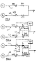
- Figures 1 and 2 show respectively the priming phase (Fig. 1) and the cutting phase (Fig. 2) succeeding each other during an arc cutting operation plasma of a piece to cut PC, for example a sheet metal steel.
- the plasma torch T is fed with pilot gas GP, by example of argon, so as to obtain a flow plasmagene FP delivered by the torch T towards the piece to cut PC.
- pilot gas GP by example of argon
- a auxiliary source SA of electric current for example a current with a voltage of 100 V and an intensity of 15 A
- Figure 2 schematizes the phase of section following the priming phase shown on the Figure 1. More precisely, in FIG. 2, during the cutting phase, the pilot gas is replaced by a gas of cut that can be of the same nature or nature different from the pilot gas, for example oxygen or a mixture of argon and hydrogen.
- a gas of cut that can be of the same nature or nature different from the pilot gas, for example oxygen or a mixture of argon and hydrogen.
- Figure 3 schematizes the system supplying a gas-fired plasma torch T pilot and cutting gas via two different and independent gas circuits one of the other.
- the cutting gas circuit comprises a line L2 of cutting gas connected, upstream, to a source S2 of cutting gas and, downstream, to the torch T plasma, and on which line L2 are arranged, a hand regulating means of the gas pressure MR2 cutter and an EV2 solenoid valve controlling the sending cutting gas to the plasma torch T.
- FIGS. 4 and 5 show the diagram of a supply system from a plasma torch T to a gas pilot and in a cutting gas, respectively, in accordance with the present invention.
- Figure 4 schematizes the operation of the pilot gas supply system and in cutting gas during the priming phase, while the Figure 5 shows the operation of the system during the cutting phase.
- Figure 4 shows that during the phase the pilot gas is conveyed via line L1, up to the plasma torch T, since the solenoid valve EV1 controlled by the control means MP is in the open position, that is to say, it allows the passage of the pilot gas towards the torch T and that, in other the electrically controlled solenoid valve EV2 or pneumatic is it, in closed position, prohibiting then the passage of the cutting gas to the torch T.
- the regulation of the pilot gas pressure in the line L1 of pilot gas is done through means of MR1 pressure control with electric control, by example an electrically controlled regulator controlled by the control means MP.
- the pressure of the cutting gas in the line L2 cutting gas supply is performed, in this case, by regulation means MR2 pressure pneumatically controlled, which are driven by the pilot gas pressure in line L1 pilot gas.
- the line L1 of pilot gas comprises a derivation or LP pneumatic control line, connected to the line L1 of pilot gas at an SL link site located downstream of the regulating means MR1 but upstream of solenoid valve EV1.
- the MP control means in acting on the regulation means MR1 of the pressure of the pilot gas generate a first pressure P1 of pilot gas downstream of said regulating means MR1, in particular in the LP pneumatic control line, which first pressure P1 will act on the means of MR2 regulation of cutting gas pressure to fix the desired cutting gas pressure level PX when the flow rate of said cutting gas is zero (EV2 being in closed position).
- control means control the solenoid valve EV1 which closes and forbids, by the same way, the passage of the pilot gas to the plasma torch T and control, in In addition, the solenoid valve EV2 which opens and allows the passage of the cutting gas towards the torch T.
- control means also act on the regulation means MR1 of the gas pressure pilot so as to fix the pilot gas pressure to a second level of pressure P2, which generates a pressure variation within the LP control line pneumatic, which pressure variation acts by ricoché on the means of regulation MR2 of the pressure cutting gas, which are then controlled for adjust the cutting gas pressure to a pressure and a desired cutting gas flow rate.
- the device according to the present The invention makes it possible to use, as cutting gas, any type of gas, in particular gases likely to pose safety problems, such as oxygen or hydrogen, given that, according to the invention, the means of regulation of the cutting gas pressure are to order which avoids any danger, since the pressure regulating means MR2 cutting gas is not electrically controlled.
- the present invention is applicable to automatic cutting machines implementing a plasma torch or an oxycutting torch, but also on an automatic machine using a torch welding torch or, more generally, on any type of large gas distribution machine flow, in particular oxygen and / or hydrogen, requiring a sequence of different gas pressure from one and the same setpoint origin electric.
Landscapes
- Engineering & Computer Science (AREA)
- Physics & Mathematics (AREA)
- Plasma & Fusion (AREA)
- Mechanical Engineering (AREA)
- Arc Welding In General (AREA)
- Plasma Technology (AREA)
- ing And Chemical Polishing (AREA)
- Drying Of Semiconductors (AREA)
Description
- une torche de coupage par jet de gaz, de préférence une torche à plasma ;
- une première ligne d'alimentation de ladite torche en un gaz pilote ;
- un deuxième ligne d'alimentation de ladite torche en un gaz de coupage ou de soudage ;
- des moyens de pilotage ;
- des premiers moyens de régulation de la pression du gaz pilote circulant dans la première ligne, lesdits premiers moyens de régulation étant agencés sur la première ligne et étant commandés par les moyens de pilotage ;
- des deuxième moyens de régulation de la pression du gaz de coupage ou de soudage circulant dans la deuxième ligne ;
Claims (10)
- Installation automatique de coupage ou de soudage par jet de gaz, en particulier de coupage par jet de plasma, comprenant au moins :caractérisée en ce qu'elle comporte, en outre, une ligne de pilotage (LP) pneumatique reliant pneumatiquement la première ligne (L1) aux deuxième moyens de régulation (MR2), ladite ligne de pilotage (LP) étant reliée à la première ligne (L1) en aval des premiers moyens de régulation (MR1), pour permettre un réglage de la pression du gaz de coupage ou de soudage dans la deuxième ligne (L2) à partir de la pression du gaz pilote dans la première ligne (L1), en agissant sur lesdits deuxième moyens de régulation (MR2), lesdits deuxième moyens de régulation (MR2) étant choisis parmi les moyens de régulation de pression à commande pneumatique.une torche (T) de coupage ou de soudage;une première ligne (L1) d'alimentation de ladite torche (T) en un gaz pilote ;une deuxième ligne (L2) d'alimentation de ladite torche (T) en un gaz de coupage ou de soudage ;des moyens de pilotage (MP) ;des premiers moyens de régulation (MR1) de la pression du gaz pilote circulant dans la première ligne (L1), lesdits premiers moyens de régulation (MR1) étant agencés sur la première ligne (L1) et étant commandés par les moyens de pilotage (MP) ;des deuxième moyens de régulation (MR2) de la pression du gaz de coupage ou de soudage circulant dans la deuxième ligne (L2) ;
- Installation selon la revendication 1, caractérisée en ce que les premiers moyens de régulation (MR1) sont à commande électrique.
- Installation selon l'une des revendications 1 ou 2, caractérisée en ce que les moyens de pilotage (MP) sont choisis parmi les systèmes à commande numérique.
- Installation selon la revendication 2, caractérisée en ce que les premier moyens de régulation (MR1) sont choisis parmi les détendeurs à commande électrique.
- Installation selon l'une des revendications 1 à 4, caractérisée en ce qu'au moins une électrovanne (EV1, EV2) est agencée sur la première ligne (L1) et/ou la deuxième ligne (L2).
- Installation selon l'une des revendications 1 à 5, caractérisée en ce qu'au moins une électrovanne (EV1, EV2) est commandée par les moyens de pilotage (MP).
- Installation selon la revendication 5, caractérisée en ce qu'au moins une électrovanne (EV1, EV2) est agencée sur chacune desdites première et deuxième lignes (L1, L2).
- Installation selon l'une des revendications 1 à 7, caractérisée en ce que la torche (T) est une torche de coupage par jet de plasma ou un chalumeau d'oxycoupage.
- Installation selon l'une des revendications 1 à 8, caractérisée en ce que la première ligne (L1) d'alimentation est alimentée en gaz pilote issu d'au moins une source de gaz pilote (S1) et en ce que la deuxième ligne (L2) d'alimentation est alimentée en gaz de coupage ou de soudage issu d'au moins une source de gaz de coupage ou de soudage (S2).
- Procédé de coupage ou soudage, de préférence un procédé de coupage plasma, dans lequel on met en oeuvre une torche à plasma alimentée en un gaz pilote par une première ligne (L1) d'alimentation et alimentée en un gaz de coupage ou de soudage par une deuxième ligne (L2) d'alimentation, des moyens de pilotage (MP) commandant des premiers moyens de régulation (MR1) de la pression du gaz pilote circulant dans la première ligne (L1) agencés sur la première ligne (L1), et des deuxième moyens de régulation (MR2) de la pression du gaz de coupage ou de soudage circulant dans la deuxième ligne (L2), mis en oeuvre par une installation selon l'une des revendications 1 à 9, caractérisé en ce qu'on pilote les moyens de régulation du gaz de coupage ou de soudage (MR2) de manière pneumatique à partir de la pression du gaz pilote au moyen d'une ligne de pilotage (LP) pneumatique reliant pneumatiquement la première ligne (L1) d'alimentation en aval des premier moyens de régulation (MR1) aux deuxième moyens de régulation (MR2), pour permettre un réglage de la pression du gaz de coupage ou de soudage dans la deuxième ligne (L2) à partir de la pression du gaz pilote dans la première ligne (L1), en agissant sur lesdits deuxième moyens de régulation (MR2), lesdits deuxième moyens de régulation (MR2) étant choisis parmi les moyens de régulation de pression à commande pneumatique.
Applications Claiming Priority (2)
| Application Number | Priority Date | Filing Date | Title |
|---|---|---|---|
| FR0002025 | 2000-02-18 | ||
| FR0002025A FR2805193B1 (fr) | 2000-02-18 | 2000-02-18 | Pilotage de l'envoi du gaz de coupage plasma a partir de la pression du gaz pilote |
Publications (2)
| Publication Number | Publication Date |
|---|---|
| EP1125671A1 EP1125671A1 (fr) | 2001-08-22 |
| EP1125671B1 true EP1125671B1 (fr) | 2005-08-10 |
Family
ID=8847130
Family Applications (1)
| Application Number | Title | Priority Date | Filing Date |
|---|---|---|---|
| EP01400191A Expired - Lifetime EP1125671B1 (fr) | 2000-02-18 | 2001-01-24 | Pilotage de l'envoi du gaz de coupage plasma à partir de la pression du gaz pilote |
Country Status (7)
| Country | Link |
|---|---|
| US (1) | US6335505B2 (fr) |
| EP (1) | EP1125671B1 (fr) |
| AT (1) | ATE301526T1 (fr) |
| CA (1) | CA2334612A1 (fr) |
| DE (1) | DE60112485T2 (fr) |
| ES (1) | ES2247029T3 (fr) |
| FR (1) | FR2805193B1 (fr) |
Families Citing this family (11)
| Publication number | Priority date | Publication date | Assignee | Title |
|---|---|---|---|---|
| US6777638B2 (en) | 2002-11-14 | 2004-08-17 | The Esab Group, Inc. | Plasma arc torch and method of operation for reduced erosion of electrode and nozzle |
| US20060163220A1 (en) * | 2005-01-27 | 2006-07-27 | Brandt Aaron D | Automatic gas control for a plasma arc torch |
| JP4423438B2 (ja) * | 2007-06-21 | 2010-03-03 | 小池酸素工業株式会社 | プラズマ切断方法 |
| JP5589222B2 (ja) * | 2009-11-04 | 2014-09-17 | 株式会社安川電機 | 非消耗電極式アーク溶接装置 |
| US20110210101A1 (en) * | 2010-03-01 | 2011-09-01 | The Esab Group, Inc. | Processes for using a plasma arc torch to operate upon an insulation-coated workpiece |
| US8283594B2 (en) | 2010-08-09 | 2012-10-09 | The Esab Group, Inc. | System and method for supplying fluids to a plasma arc torch |
| US20120031881A1 (en) * | 2010-08-09 | 2012-02-09 | The Esab Group, Inc. | Blow-Back Plasma Arc Torch With Shield Fluid-Cooled Electrode |
| US8395074B2 (en) | 2010-12-03 | 2013-03-12 | Kaliburn, Inc. | Plasma ARC systems with cutting and marking functions |
| JP5709505B2 (ja) * | 2010-12-15 | 2015-04-30 | 東京エレクトロン株式会社 | プラズマ処理装置、プラズマ処理方法、および記憶媒体 |
| US9427820B2 (en) | 2012-10-19 | 2016-08-30 | Hypertherm, Inc. | Thermal torch lead gas delivery methods and related systems and devices |
| US9510435B2 (en) | 2013-06-24 | 2016-11-29 | Victor Equipment Company | Gas control system for a plasma ARC torch |
Family Cites Families (6)
| Publication number | Priority date | Publication date | Assignee | Title |
|---|---|---|---|---|
| JPS5116379B2 (fr) * | 1973-07-20 | 1976-05-24 | ||
| US5290995A (en) * | 1991-12-20 | 1994-03-01 | Esab Welding Products, Inc. | Plasma arc cutting system having fluid metering and power control systems |
| JPH06226451A (ja) * | 1993-01-29 | 1994-08-16 | Komatsu Ltd | プラズマ切断方法および切断装置 |
| DE19536150C2 (de) * | 1995-09-28 | 1997-09-04 | Esab Hancock Gmbh | Einrichtung und Verfahren zur Gassteuerung eines Plasmabrenners einer Plasmaschneidanlage |
| US5844201A (en) * | 1997-01-21 | 1998-12-01 | Dibacco; Pino | Welding torch apparatus |
| US6054669A (en) * | 1998-05-20 | 2000-04-25 | The Esab Group, Inc. | Plasma marking torch and method of operating same |
-
2000
- 2000-02-18 FR FR0002025A patent/FR2805193B1/fr not_active Expired - Fee Related
-
2001
- 2001-01-24 EP EP01400191A patent/EP1125671B1/fr not_active Expired - Lifetime
- 2001-01-24 DE DE60112485T patent/DE60112485T2/de not_active Expired - Fee Related
- 2001-01-24 ES ES01400191T patent/ES2247029T3/es not_active Expired - Lifetime
- 2001-01-24 AT AT01400191T patent/ATE301526T1/de not_active IP Right Cessation
- 2001-02-08 CA CA002334612A patent/CA2334612A1/fr not_active Abandoned
- 2001-02-16 US US09/784,193 patent/US6335505B2/en not_active Expired - Fee Related
Also Published As
| Publication number | Publication date |
|---|---|
| DE60112485D1 (de) | 2005-09-15 |
| DE60112485T2 (de) | 2006-04-20 |
| US6335505B2 (en) | 2002-01-01 |
| FR2805193A1 (fr) | 2001-08-24 |
| EP1125671A1 (fr) | 2001-08-22 |
| CA2334612A1 (fr) | 2001-08-18 |
| ES2247029T3 (es) | 2006-03-01 |
| ATE301526T1 (de) | 2005-08-15 |
| FR2805193B1 (fr) | 2002-05-10 |
| US20010025834A1 (en) | 2001-10-04 |
Similar Documents
| Publication | Publication Date | Title |
|---|---|---|
| US8129652B2 (en) | Welding stability system and method | |
| US20050045600A1 (en) | Gas flow pre-charge for a plasma arc torch | |
| US9186743B2 (en) | Welding and gouging systems with multiple power settings | |
| EP1049560B1 (fr) | Appareil a souder | |
| US20020117489A1 (en) | Method and system for hot wire welding | |
| EP1125671A1 (fr) | Pilotage de l'envoi du gaz de coupage plasma à partir de la pression du gaz pilote | |
| DE69126527T2 (de) | Verfahren und vorrichtung zur verringerung der elektrodenabnutzung in einem plasmalichtbogenbrenner | |
| US7326875B2 (en) | Method for supplying a plasma torch with a gas, mixed gas, or gas mixture, comprising volumetric flow regulation in combination with pressure regulation; and arrangement for carrying out said method | |
| US20070056944A1 (en) | Method for controlling and/or adjusting a welding process and welding device for carrying out a welding process | |
| CA2345836A1 (fr) | Methode et systeme de soudage au fil chaud | |
| NO124042B (fr) | ||
| US20020185477A1 (en) | Process for operating a plasma arc torch | |
| US20180290229A1 (en) | Gas supply device, gas supply device having mixing function, welding device, and gas supply method | |
| US20090107959A1 (en) | Arc Welding Initiation System and Method | |
| US7642486B2 (en) | Welding device with arc termination control | |
| US20010045415A1 (en) | Process for operating a plasma arc torch | |
| US6933463B2 (en) | Main arc ignition device and main arc ignition control method of plasma cutting machine | |
| US4803405A (en) | Plasma processing apparatus and method | |
| CA2455644C (fr) | Dispositif d'economie de gaz de protection | |
| JP2019051546A (ja) | 溶接システム | |
| KR100263363B1 (ko) | 플라즈마 아아크 이용 기기 | |
| WO2010141544A1 (fr) | Soudage sous laitier electro-conducteur a alimentation de soudage a equilibre variable, potentiel constant, en courant alternatif a ondes carrees | |
| EP1559497A1 (fr) | Procédé et installation de coupage plasma à courant asservi au débit ou à la pression du gaz plasmagène | |
| US20050242075A1 (en) | Method and apparatus for short circuit welding with pulse gas | |
| AU2010201282A1 (en) | Method and apparatus for welding with start control |
Legal Events
| Date | Code | Title | Description |
|---|---|---|---|
| PUAI | Public reference made under article 153(3) epc to a published international application that has entered the european phase |
Free format text: ORIGINAL CODE: 0009012 |
|
| AK | Designated contracting states |
Kind code of ref document: A1 Designated state(s): AT BE CH CY DE DK ES FI FR GB GR IE IT LI LU MC NL PT SE TR |
|
| AX | Request for extension of the european patent |
Free format text: AL;LT;LV;MK;RO;SI |
|
| 17P | Request for examination filed |
Effective date: 20020222 |
|
| AKX | Designation fees paid |
Free format text: AT BE CH CY DE DK ES FI FR GB GR IE IT LI LU MC NL PT SE TR |
|
| 17Q | First examination report despatched |
Effective date: 20040730 |
|
| GRAP | Despatch of communication of intention to grant a patent |
Free format text: ORIGINAL CODE: EPIDOSNIGR1 |
|
| GRAS | Grant fee paid |
Free format text: ORIGINAL CODE: EPIDOSNIGR3 |
|
| GRAA | (expected) grant |
Free format text: ORIGINAL CODE: 0009210 |
|
| AK | Designated contracting states |
Kind code of ref document: B1 Designated state(s): AT BE CH CY DE DK ES FI FR GB GR IE IT LI LU MC NL PT SE TR |
|
| PG25 | Lapsed in a contracting state [announced via postgrant information from national office to epo] |
Ref country code: TR Free format text: LAPSE BECAUSE OF FAILURE TO SUBMIT A TRANSLATION OF THE DESCRIPTION OR TO PAY THE FEE WITHIN THE PRESCRIBED TIME-LIMIT Effective date: 20050810 Ref country code: FI Free format text: LAPSE BECAUSE OF FAILURE TO SUBMIT A TRANSLATION OF THE DESCRIPTION OR TO PAY THE FEE WITHIN THE PRESCRIBED TIME-LIMIT Effective date: 20050810 Ref country code: IE Free format text: LAPSE BECAUSE OF FAILURE TO SUBMIT A TRANSLATION OF THE DESCRIPTION OR TO PAY THE FEE WITHIN THE PRESCRIBED TIME-LIMIT Effective date: 20050810 Ref country code: AT Free format text: LAPSE BECAUSE OF FAILURE TO SUBMIT A TRANSLATION OF THE DESCRIPTION OR TO PAY THE FEE WITHIN THE PRESCRIBED TIME-LIMIT Effective date: 20050810 |
|
| REG | Reference to a national code |
Ref country code: GB Ref legal event code: FG4D Free format text: NOT ENGLISH |
|
| REG | Reference to a national code |
Ref country code: CH Ref legal event code: EP |
|
| REG | Reference to a national code |
Ref country code: IE Ref legal event code: FG4D Free format text: LANGUAGE OF EP DOCUMENT: FRENCH |
|
| REF | Corresponds to: |
Ref document number: 60112485 Country of ref document: DE Date of ref document: 20050915 Kind code of ref document: P |
|
| PG25 | Lapsed in a contracting state [announced via postgrant information from national office to epo] |
Ref country code: DK Free format text: LAPSE BECAUSE OF FAILURE TO SUBMIT A TRANSLATION OF THE DESCRIPTION OR TO PAY THE FEE WITHIN THE PRESCRIBED TIME-LIMIT Effective date: 20051110 Ref country code: SE Free format text: LAPSE BECAUSE OF FAILURE TO SUBMIT A TRANSLATION OF THE DESCRIPTION OR TO PAY THE FEE WITHIN THE PRESCRIBED TIME-LIMIT Effective date: 20051110 Ref country code: GR Free format text: LAPSE BECAUSE OF FAILURE TO SUBMIT A TRANSLATION OF THE DESCRIPTION OR TO PAY THE FEE WITHIN THE PRESCRIBED TIME-LIMIT Effective date: 20051110 |
|
| GBT | Gb: translation of ep patent filed (gb section 77(6)(a)/1977) |
Effective date: 20051104 |
|
| PGFP | Annual fee paid to national office [announced via postgrant information from national office to epo] |
Ref country code: FR Payment date: 20051208 Year of fee payment: 6 |
|
| PGFP | Annual fee paid to national office [announced via postgrant information from national office to epo] |
Ref country code: GB Payment date: 20051213 Year of fee payment: 6 |
|
| PGFP | Annual fee paid to national office [announced via postgrant information from national office to epo] |
Ref country code: NL Payment date: 20051214 Year of fee payment: 6 |
|
| PGFP | Annual fee paid to national office [announced via postgrant information from national office to epo] |
Ref country code: DE Payment date: 20051215 Year of fee payment: 6 |
|
| PG25 | Lapsed in a contracting state [announced via postgrant information from national office to epo] |
Ref country code: PT Free format text: LAPSE BECAUSE OF FAILURE TO SUBMIT A TRANSLATION OF THE DESCRIPTION OR TO PAY THE FEE WITHIN THE PRESCRIBED TIME-LIMIT Effective date: 20060110 |
|
| PGFP | Annual fee paid to national office [announced via postgrant information from national office to epo] |
Ref country code: ES Payment date: 20060113 Year of fee payment: 6 |
|
| PGFP | Annual fee paid to national office [announced via postgrant information from national office to epo] |
Ref country code: BE Payment date: 20060120 Year of fee payment: 6 |
|
| PG25 | Lapsed in a contracting state [announced via postgrant information from national office to epo] |
Ref country code: LU Free format text: LAPSE BECAUSE OF NON-PAYMENT OF DUE FEES Effective date: 20060131 Ref country code: CH Free format text: LAPSE BECAUSE OF NON-PAYMENT OF DUE FEES Effective date: 20060131 Ref country code: LI Free format text: LAPSE BECAUSE OF NON-PAYMENT OF DUE FEES Effective date: 20060131 Ref country code: MC Free format text: LAPSE BECAUSE OF NON-PAYMENT OF DUE FEES Effective date: 20060131 |
|
| PGFP | Annual fee paid to national office [announced via postgrant information from national office to epo] |
Ref country code: IT Payment date: 20060131 Year of fee payment: 6 |
|
| REG | Reference to a national code |
Ref country code: ES Ref legal event code: FG2A Ref document number: 2247029 Country of ref document: ES Kind code of ref document: T3 |
|
| REG | Reference to a national code |
Ref country code: IE Ref legal event code: FD4D |
|
| PLBE | No opposition filed within time limit |
Free format text: ORIGINAL CODE: 0009261 |
|
| STAA | Information on the status of an ep patent application or granted ep patent |
Free format text: STATUS: NO OPPOSITION FILED WITHIN TIME LIMIT |
|
| 26N | No opposition filed |
Effective date: 20060511 |
|
| REG | Reference to a national code |
Ref country code: CH Ref legal event code: PL |
|
| PG25 | Lapsed in a contracting state [announced via postgrant information from national office to epo] |
Ref country code: DE Free format text: LAPSE BECAUSE OF NON-PAYMENT OF DUE FEES Effective date: 20070801 |
|
| GBPC | Gb: european patent ceased through non-payment of renewal fee |
Effective date: 20070124 |
|
| NLV4 | Nl: lapsed or anulled due to non-payment of the annual fee |
Effective date: 20070801 |
|
| REG | Reference to a national code |
Ref country code: FR Ref legal event code: ST Effective date: 20070930 |
|
| PG25 | Lapsed in a contracting state [announced via postgrant information from national office to epo] |
Ref country code: GB Free format text: LAPSE BECAUSE OF NON-PAYMENT OF DUE FEES Effective date: 20070124 |
|
| BERE | Be: lapsed |
Owner name: *SAFMATIC Effective date: 20070131 |
|
| PG25 | Lapsed in a contracting state [announced via postgrant information from national office to epo] |
Ref country code: BE Free format text: LAPSE BECAUSE OF NON-PAYMENT OF DUE FEES Effective date: 20070131 |
|
| PG25 | Lapsed in a contracting state [announced via postgrant information from national office to epo] |
Ref country code: NL Free format text: LAPSE BECAUSE OF NON-PAYMENT OF DUE FEES Effective date: 20070801 |
|
| REG | Reference to a national code |
Ref country code: ES Ref legal event code: FD2A Effective date: 20070125 |
|
| PG25 | Lapsed in a contracting state [announced via postgrant information from national office to epo] |
Ref country code: FR Free format text: LAPSE BECAUSE OF NON-PAYMENT OF DUE FEES Effective date: 20070131 |
|
| PG25 | Lapsed in a contracting state [announced via postgrant information from national office to epo] |
Ref country code: ES Free format text: LAPSE BECAUSE OF NON-PAYMENT OF DUE FEES Effective date: 20070125 |
|
| PG25 | Lapsed in a contracting state [announced via postgrant information from national office to epo] |
Ref country code: CY Free format text: LAPSE BECAUSE OF FAILURE TO SUBMIT A TRANSLATION OF THE DESCRIPTION OR TO PAY THE FEE WITHIN THE PRESCRIBED TIME-LIMIT Effective date: 20050810 |
|
| PG25 | Lapsed in a contracting state [announced via postgrant information from national office to epo] |
Ref country code: IT Free format text: LAPSE BECAUSE OF NON-PAYMENT OF DUE FEES Effective date: 20070124 |