EP1124749B1 - Improvements in a track for stairlifts - Google Patents
Improvements in a track for stairlifts Download PDFInfo
- Publication number
- EP1124749B1 EP1124749B1 EP99949248A EP99949248A EP1124749B1 EP 1124749 B1 EP1124749 B1 EP 1124749B1 EP 99949248 A EP99949248 A EP 99949248A EP 99949248 A EP99949248 A EP 99949248A EP 1124749 B1 EP1124749 B1 EP 1124749B1
- Authority
- EP
- European Patent Office
- Prior art keywords
- rail
- carriage
- drive
- stairlift
- rollers
- Prior art date
- Legal status (The legal status is an assumption and is not a legal conclusion. Google has not performed a legal analysis and makes no representation as to the accuracy of the status listed.)
- Expired - Lifetime
Links
Images


Classifications
-
- B—PERFORMING OPERATIONS; TRANSPORTING
- B66—HOISTING; LIFTING; HAULING
- B66B—ELEVATORS; ESCALATORS OR MOVING WALKWAYS
- B66B9/00—Kinds or types of lifts in, or associated with, buildings or other structures
- B66B9/06—Kinds or types of lifts in, or associated with, buildings or other structures inclined, e.g. serving blast furnaces
- B66B9/08—Kinds or types of lifts in, or associated with, buildings or other structures inclined, e.g. serving blast furnaces associated with stairways, e.g. for transporting disabled persons
- B66B9/0846—Guide rail
Definitions
- This invention relates to stair mounted elevators or lifts, commonly known as stairlifts.
- a stairlift in the form of a carriage mounted for movement along a rail, is a well known form of apparatus for moving aged or handicapped persons up and down a staircase.
- Such a form of apparatus needs to be designed so that the carriage runs smoothly along the rail yet is resistant to forms of movement other than linear movement along the rail.
- Particular movements which need to be resisted are skewing about the rail, which might cause the carriage to jam as it moves along the rail; tilting of the carriage about an axis transverse of the rail which, unless strictly controlled, can cause the carriage seat to move off the horizontal and alarm a user; and rotation of the carriage about the rail axis which, again, would have an alarming affect on a user.
- the desired smoothness of longitudinal movement, as well as resistance to unwanted movement, is typically provided by including within the carriage, spaced pairs of rollers which serve to mount the carriage on the rail.
- rollers which serve to mount the carriage on the rail.
- rail designs have tended to be quite broad so that the roller spacings can be as wide as possible. This, in turn, has meant that the resulting stairlift has tended to occupy a considerable margin down one edge of a staircase.
- Typical prior art stairlifts have at least six pairs of rollers to provide the necessary rolling support to the carriage whilst resisting the undesired movements mentioned above. Obviously the more rollers which are included, the greater the cost. However, even with six roller pairs, some prior art stairlifts still display a degree of uncontrolled movement in the assembly due to the need to provide clearance between opposite sides of the rollers, and the rail.
- DE-3020379 discloses stairlift apparatus including:
- GB-2137589 discloses stairlift apparatus including:
- the invention provides stairlift apparatus including:
- the construction and arrangement is such that said rollers and said rail further operate to resist tilting and skewing movement of said carriage with respect to said rail.
- said rail has at least three rolling surfaces arranged about the outer surface of said rail, a roller contacting each of said rolling surfaces. More preferably said rail includes four rolling surfaces arranged about said cross-section to extend longitudinally of said rail, a pair of longitudinally spaced rollers being provided for each of said rolling surfaces.
- Said rolling surfaces are conveniently provided as an upper pair and a lower pair and said rail preferably further includes rail mounting means defined between said lower pair of rolling surfaces.
- the individual rolling surfaces of each pair, and the juxtaposed surfaces of the different pairs, are preferably perpendicular to each other and drive transfer means is preferably provided on or adjacent said drive surface.
- the drive transfer means is preferably provided on or adjacent one of the upper rolling surfaces.
- the drive transfer means could comprise a section of the rail adapted for frictional engagement with the carriage, said drive transfer means preferably comprises a gear rack.
- the apparatus as set forth above may further include rack cover means to at least partially overlie said rack and screen said rack from sight when the rail is viewed from above.
- This rack cover means preferably comprises a moulding or extrusion fixed above the rack and extending longitudinally of the rail.
- the periphery of said drive wheel may be engageable with said drive transfer means so that, upon rotation of said drive wheel, said carriage is moved longitudinally of said rail; and said drive means mounted within said carriage; said drive means having a drive shaft rotatable about a drive axis, said drive wheel being mounted for rotation on said drive shaft; the arrangement being characterised in that said drive means does not overlie said rail when viewed in a direction perpendicular to said drive axis.
- the drive transfer means preferably comprises a rack and said drive wheel comprises a pinion which, in use, engages with said rack.
- rollers which support the carriage on the rail are identical and the mounting arrangement of the rollers is preferably such that each of said rollers is only loaded substantially perpendicularly to its respective axis of rotation.
- the carriage preferably includes a pair of spaced side plates which extend down to at least partially overlie opposite parts of said rail, said rollers extending from said side plates.
- These side plates preferably comprise outer surface parts of said carriage and may include bracing means on the inner surfaces thereof, said plurality of rollers being mounted on said bracing means.
- Said side plates and said bracing means are preferably press formed from sheet metal and subsequently welded together.
- said rollers are preferably provided in co-operating pairs, wherein some of said rollers of each pair rotate about fixed axes whilst the axes of the remainder of said rollers in each pair may be displaced in directions perpendicular to said axes.
- the present invention provides a novel configuration of stairlift apparatus which is un-handed; compact, in that it occupies less space and has less visual impact than typical prior art stairlifts; and also incorporates a reduced number of operating parts with innovative assembly features in order to function efficiently and safely.
- the stairlift includes a carriage 30 mounted substantially above, for movement along, a tubular rail 31 of constant cross section.
- Two roller sets 32 and 33 [Figure 2) support the carriage on the rail, the rail and roller configuration being such as to permit smooth movement of the carriage longitudinally of the rail yet prevent tilting, skewing and rotation of the carriage about the rail.
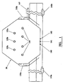
- each of the roller sets 32 and 33 comprises four rollers, the set 32 being shown in Figure 4 and comprising rollers 32a, 32b, 32c and 32d.
- the roller set 33 is identical to the roller set 32 but is spaced along the carriage as is evident from Figure 2.
- All rollers of both of the roller sets 32 and 33 are preferably identical.
- the rail 31 has a rolling surface for the corresponding rollers of the sets 32 and 33, the rolling surfaces being indicated by reference numerals 34a, 34b, 34c and 34d.
- the rolling surfaces are arranged about the cross section of the tubular rail, extend longitudinally of the rail 31 and are formed by the same elements that define the structural elements of the tube. This leads to a compact and structurally efficient rail and is in contrast to typical prior art stairlift rails in which the main supporting rolling surfaces are typically spaced across the rail, often supplemented with vertical surfaces which act as bearing surfaces for anti-skew rollers.
- each of the rolling surfaces 34a, 34b, 34c, and 34d is preferably planar in form and, in this form, juxtaposed surfaces are perpendicular.
- surfaces 34a and 34b and surfaces 34c and 34d are perpendicular.
- the planes of surfaces 34b and 34c, and 34d and 34a are perpendicular in the form shown.
- the surfaces may be viewed as being arranged in upper and lower pairs, the upper pair comprising surfaces 34b and 34c, and the lower pair comprising surfaces 34a and 34d.
- a mounting section 36 which serves to facilitate mounting of the rail 31 on the stairs of a staircase 37 ( Figure 13), and which may also serve as a mounting base for various other components as will be described in greater detail below.
- the mounting section 36 includes a downwardly facing channel 38 having inwardly aligned lower flanges 39.
- a drive or traction surface is also provided on the rail, preferably parallel to one of the upper rolling surfaces, in this case the rolling surface 34c. It should be appreciated, however, that the drive or traction surface could be provided in a variety of locations about the rail periphery including, for example, on an undersurface of the rail.
- the traction surface could be a surface adapted for friction drive, and thus be a co-planar section or extension of surface 34c, in this case the surface 34c includes suitable drive mounting means 40 to mount and retain drive transfer means 41, which drive transfer means preferably comprises a rack.
- the drive mounting means 40 comprises a further channel defined in part by inwardly aligned arms 42 having an access slot 43 therebetween.
- the channel 40 is sized and configured to slidably receive and retain a plurality of fixing bases preferably in the form of captive nuts 44 although these nuts 44 could be replaced by one or more tapped strips which slide into the channel 40.
- the rack 41 is sized to overlie the access slot 43 and bear on outer surface parts of the arms 42. Fixing means, preferably in the form of machine screws 45, are then passed through countersunk holes 46 formed through the rack 41, passed through the access slot 43 to engage in the captive nuts 44. It will be appreciated that as the screws 45 are tightened in the nuts 44, the rack is drawn down against outer surface parts of the arms 42 whilst the nuts are drawn up against inner surface parts of the arms 42 thus clamping the rack firmly in position.
- This arrangement allows the mounting holes 46 to be preformed in the rack and for the rack to be readily mounted in position quickly and accurately, and easily removed and replaced if necessary.
- the rail could be provided with a further channel in rolling surface 34b, the further channel being identical in form to channel 40 and being positioned on surface 34b so as to be a mirror image of channel 40 about the central vertical axis of the rail.
- the rail could be "handed" by the installer, on site.
- the rack 41 is further secured at each end thereof by fixing plates 47, one of which is shown in Figure 9.
- the plate is fixed to surface part 34c by machine screws 48 or the like, so as to stand proud of the surface part 34c, and includes a step 49 which engages the end of the rack and thus prevents any movement of the rack 41 to the left as shown in Figure 9.
- An identical plate (not shown) fixed at the opposite end of the rack 41 prevents movement in the opposite direction.
- the plates 47 further serve as mechanical safety stops for the carriage as it approaches the ends of the rail in a manner which will be described in greater detail below.
- the rail preferably further includes some means to at least partially cover the rack when the apparatus is viewed from above so as to reduce the possibility of interference with the rack and, hopefully, to enhance the aesthetic appearance of the apparatus. Whilst this cover means could be formed integrally with the rail 31, in the form shown a separate rack cover or masking member 50 ( Figure 7) is provided, preferably in the form of a plastics moulding or extrusion. As can be seen, the member 50 has a covering arm 51 which provides the covering or masking function, and a fixing base 52 which serves to fix the member 50 on to the rail 31. In the form shown, both edges of the base 52 curve down into side margins 53a, 53b each of which has a fixing lip 54 defined on the lower inner edge thereof.
- cover member 50 preferably further includes a pair of upwardly aligned ribs 56 extending along the upper surface thereof, the purpose of which will become apparent later in this description.
- the rail section as above described is conveniently extruded from aluminium. Suitable grades of aluminium include 6063, hardness T6.
- the rail may be left in its natural, as extruded, form, or may be painted or anodised. Alternatively, the rail could be pultruded in a variety of materials, both metallic and non-metallic (or combinations of metallic and non-metallic) or the rail could even be fabricated from sections of plate material.
- the joining means includes a pair of joining channels 58, formed so as to extend along the inner surface of the rail 31, the channels 58 receiving and retaining joining pins 60.
- the joining pins 60 are selected or formed to be an interference fit within the channels 58 and are first located in a first one of the rail sections so that, as shown in Figure 12, parts thereof project out from the first rail section. The second rail section is then aligned with the first section, and moved toward the first section so that the projecting parts of the pins 60 engage in the channels 58 of the second rail section.
- each pin 60 is preferably knurled over part 59 of the outer surface thereof.
- each pin is inserted into a channel 58 of the first rail section, it is so inserted until at least part, and preferably substantially all, of the knurled section 59 is located in the channel 58 of the first section.
- the knurling 59 serves to firmly retain the pins in the channels 58.
- channels 58 could be located at any points on the inner periphery of the rail 31, the same are preferably located at the inner junctions between the juxtaposed pairs of rolling surfaces 34a, 34b and 34c, 34d. In this way, any joint along the rolling surfaces is securely aligned and firmly braced by the joining pins and thus overcomes the problem, experienced with prior art rail joints, in adjacent sections of rolling surface being slightly mis-aligned, thus causing some bumping as the carriage rides over the joint.
- the rail joint as described above is preferably braced by outer bracing plates 62 which span the joint.
- the bracing plates 62 are fixed to inner mounting plates 63 located within the mounting channel 38 provided on the lower edge of the rail 31.
- Machine screws 64 are used to fix the plates 62 to the plates 63.
- the channels 58 may serve a further function.
- covers (not shown) are typically provided to close off the ends of the extrusion. These covers may be fixed into position by fasteners (not shown) which pass through the cove rs and engage in the channel 58. Whilst the fasteners could be self-tapping, for this application threaded inserts are preferably inserted in the channels 58.
- the mounting channel 38 serves as a location for mounting means used to mount the rail 31 in a staircase.
- the mounting means may comprise a plurality of like brackets 66, each comprising a rail engaging part 67 and a stair engaging part 68.
- the rail engaging part 67 is engaged to the rail 31 through a single lock bolt 70 engaging in lock plate 69 fixed within channel 38.
- the arrangement is such that, prior to being locked, the bolt 70 defines a pivot aligned with the central vertical axis 72 of the rail. This allows the bracket 66 to be pivoted about the axis 72 before the bolt 70 is locked.
- the lock plate 69 With the lock bolt 70 slackened, the lock plate 69, and thus the bracket 66, can be positioned at any point along the rail and the bracket can be rotated about axis 72. When all components have been aligned to the installer's satisfaction, the lock bolt 70 is tightened, thus locking the components in position.
- the edges of the centre part thereof are turned down to provide strengthening flanges 73.
- the risk of the rail engagement part deforming may be further reduced by press forming the centre section of part 67 to a bell shape, which bell shape projects through the space between lower channel flanges 39 and engages the lower surface of lock plate 69.
- FIG. 17 The assembly of the rail on a mounting bracket is shown in a horizontal position in Figure 17, this being an unlikely configuration for a stairlift rail.
- Figure 18 A more realistic arrangement is shown in Figure 18 in which the rail 11 is at angle ⁇ to a horizontal plane 75.
- the plane 75 is typically represented by a stair tread and we have found, in the past, that there can be considerable horizontal mis-alignment of stair treads, including mis-alignment across the stair treads.
- the two parts 67 and 68 are pivoted together along further pivot axis 78 which is orthogonal to axis 72 and allows the brackets to accommodate different rail gradients (differences in angle ⁇ ) as well as a degree of different gradient on the various stair treads.
- a hinge mechanism 80 is shown between rail section 81 fixed to the staircase 37, and hinged rail section 82. Whilst the hinge mechanism could be manual in operation, in the form shown the mechanism 80 includes a motor 83 driving a right-angle drive gearbox 84.
- the motor and gearbox combination is preferably arranged along the rail axis and is conveniently suspended below the fixed rail part 81, being mounted in the fixing channel 38 by suitable fixing bolts (not shown) engaging in captive fixing plates 79 slidable along but lockable within the channel 38. Being mounted in this way, the position of the motor 83 and gearbox 84 can be readily adjusted along the rail part 81, and any mis-alignment readily eliminated.
- the output shaft 85 of the right angle drive gearbox lies across the rail and conveniently defines the hinge axis.
- arms 86 which project from the hinged rail section 82 can be mounted directly on the output shaft 85.
- a mounting bracket 88 is provided on the underside of the hinged section 82 to link the outer ends of arms 86 and to ensure alignment of the rail sections as the hinged section 82 is pivoted down into end alignment with the fixed rail section 81. As can be seen, the bracket 88 is also fixed to the hinged rail section 82 by way of channel 38.
- balancing means are preferably provided.
- this comprises a spring, preferably a gas spring 90.
- a lower powered motor can be used to provide the requisite hinging action.
- Suitable support bracing is preferably provided to the mating ends of the rail parts to minimize deformation of the rail parts as the laden carriage travels over the hinge joint.
- This support bracing can be seen most clearly in Figure 16 and, in the form shown, comprises an inner bracing channel support 92 which overlies the hinge line and is fixed to the upper inner surface of the fixed rail part.
- a supplementary bar part 93 may be provided to occupy the cavity formed between the upper part of the support 92 and the inner, upper central surface part of the rail section.
- the support bracing may further include an external channel member 94, again overlying the hinge line, which surrounds the lower parts of the two rail sections, when aligned, and prevents outward deformation of those sections when under load.
- the channel member 94 is secured to the fixed rail section by bolts (not shown) engaging in suitable fixings (not shown) mounted in the channel 38.
- carriage 30 includes a main chassis 100 which, when the carriage is mounted in position on the rail 31, spans over the rail.
- a main chassis 100 which, when the carriage is mounted in position on the rail 31, spans over the rail.
- side plates 101a and 101b which extend down to overlie at least part of both sides of the rail 31.
- the side plates also serve as mountings for the individual rollers of the roller sets 32 and 33.
- the chassis 100 includes a mounting base 102 which is angled to the remainder of the base and serves as a mounting surface for main drive motor 104 and gearbox 105.
- the mounting base 102 may be formed integrally with the forming process for the chassis i.e. may be press formed when the chassis is press formed, or may be fixed by welding or bolting to the chassis 100.
- the chassis 100 also includes a central aperture 106. This gives clearance to enable drive pinion 108, mounted on output shaft 107 of gearbox 105, to engage with drive rack 41 located below the chassis 100 on rail 31.
- each of the side plates 101a and 101b are preferably provided with internal triangulated bracing members 110a and 110b respectively, the bracing members extending along the carriage and adding considerable stiffness to that section of the carriage which provides the mount to the rail 31.
- the bracing members also provide convenient mounting points for the rollers of rollers sets 32 and 33. Indeed, the configuration of bracing which provides significant natural strength - a triangle - also perfectly positions the rollers 32 and 33 to engage the perpendicular rolling surfaces of the rail 31. This all helps to ensure that a compact, yet stable, carriage configuration results.
- the carriage is preferably further braced in the vicinity of the roller mounts by folding the centre parts of the side plates 101a and 101b around to form fixed centre end cover parts 103a and 103b (shown in dotted outline in Figure 3).
- the end cover parts 103a and 103b are, in turn, fixed to the chassis 100.
- the bracing members 110a, 110b include threaded bosses to receive axle pins 112 and sleeves 113 which mount each of the rollers 32, 33.
- the sleeves 113 which mount the top rollers 32b, 33b and 32c, 33c are preferably provided with concentric through-bores whilst those which mount the lower rollers 32a, 33a and 32d, 33d are preferably provided with eccentric through bores.
- the axes of the rear roller sets 32c, 33c and 32d, 33d could be fixed whilst those of the front sets 32a, 33a and 32b, 33b could be provided on eccentrics so as to provide the necessary adjustment.
- the rollers 32, 33 may be formed from any suitable material, one example being nylon which is preferably impregnated with molybdenum sulphide.
- the drive wheel 108 comprises a compatible pinion.
- the drive transfer means could comprise a simple surface, perhaps patterned or roughened, and the wheel 108 a simple wheel arranged to frictionally engage the transfer surface.
- the motor 104 and gearbox 105 are spaced away from the rail and, when viewed in a direction perpendicular to the axis of output shaft 107, the motor and gearbox combination do not overlie the rail 11.
- the rack 41 could be packed upwardly to correctly engage a smaller diameter pinion 108.
- the pinion 108 engages rack 41 which is located on one of the upper rolling surfaces 34c whilst the gearbox substantially overlies, but is spaced from, the other upper rolling surface 34b.
- rack 41 which is located on one of the upper rolling surfaces 34c whilst the gearbox substantially overlies, but is spaced from, the other upper rolling surface 34b.
- side plates 101a and 101b also preferably comprise part of the outer surface of the carriage.
- a further cross member 115 may, as shown, be provided which projects between upper parts of the side plates 101 to stiffen the carriage and serve as a mount for other components as will be described in greater detail below.
- the chassis 100, side plates 101, bracing members 110 and cross member 115 are preferably all press formed from sheet metal, and are then located in a jig, and spot welded together. This considerably simplifies fabrication of the carriage and enables a lighter structure to achieve desired strength parameters.
- the carriage 30 also includes a novel arrangement for mounting a stairlift chair (not shown) on the carriage.
- chair interface unit 120 is mounted on the carriage 30, the interface unit 120 having downwardly extending side members 122 which at least partly overlie the side plates 101a and 101b of the carriage 30.
- a central mounting hole 124 in each of the side members 122 is aligned with one of mounting bosses 125a, 125b and 125c ( Figure 1) fixed in the side plates 101 of the carriage.
- a mounting bolt 126 is then passed through the aligned hole, and engaged in the selected boss, to provide pivotal support for the interface unit, and thus the chair.
- a locking bolt 130 is passed through one of the arcuate slots 132, in the interface unit, which has a locking aperture 134, in side plate 101, exposed thereunder, and is engaged in the aperture 134 and tightened to fix the chair in position.
- interface unit 120 also serves as a mounting point for footrest 136.
- stairlift installations include various safety features to minimise accidental harm to users of the installation or to persons who may come into contact with the stairlift during operation.
- One requirement is that the stairlift carriage be brought to a halt, without manual intervention, when it reaches the ends of the rail. This is to ensure that the carriage is not inadvertently powered off the rail.
- Another requirement is that the carriage be brought to a halt in the event the carriage encounters an obstacle in its path whilst travelling along the rail.
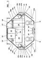
- the end stop switching is provided by a bank of three stop switches, a first switch 140, second switch 141 and third switch 142, the bank of switches being mounted on the lower inner surface of side plate 101a and being positioned so that the centre switch 141 lies on, or very close to, the vertical geometric centre of the carriage when the carriage is viewed in the position shown in Figure 2.
- Switch operating means 145a, 145b are mounted at or adjacent each end of the rail. As the carriage arrives at the end to the left in Figure 1, the switch 140 contacts the switch operating member 145a and cuts power to the motor 104. Should the switch 140 fail to operate, the carriage continues until ultimate or back-up switch 141 engages the member 145a and cuts power to all electrical components in the carriage.
- switch 142 When the carriage is moving in the opposite direction, switch 142 first contacts switch operating member 145b. If switch 142 fails to operate then ultimate or back-up switch 141 is again brought into play, but this time through contact with member 145b.
- All three switches 140, 141 and 142 are preferably identical.
- the members 145a at both ends of the rail are preferably identical and are conveniently mounted using mounting channel 38.
- the members 145 are locked into positions by locking bolts 146 acting in captive nuts 147 slidable within the channel 38. In this way, the safety stopping positions at either end of the rail can be easily adjusted and reliably fixed.
- a further safety back-up is provided to supplement the switches 140, 141 and 142.
- the back-up switch 142 also fails to cut power to the drive motor 104, the structure of the carriage is designed to foul on rack retaining member 47 which acts as a mechanical barrier to further movement of the carriage.
- the carriage 30 includes hinged means which, in the form shown, comprise flaps 150a and 150b mounted on opposite ends of the carriage 30, the flaps 150 being preferably folded or press formed from single section s of sheet metal. As can be seen from Figures 1 to 3, the flaps have lower sections 151 which extend down to lie on opposite sides of the rail 31. Springs 152 acting between the flaps 150 and the carriage ends bias the flaps away from the carriage ends.
- each flap 150a, 150b has an inwardly turned lip 153 which engages over the upper edges of carriage end parts 103a, 103b to provide a pivotal mount for each flap.
- Each flap further includes side flanges 154 which are formed with hooked keepers 155.
- the keepers 155 are configured to engage over the lower edges of slots 156a and 156b formed in the carriage end parts 103a and 103b to thus limit the displacement of the flaps by the springs 152.
- the flaps 150 are held down in position over carriage end parts 103 by upper cover sections 158a and 158b, the upper cover sections further contributing to the enclosure of the interior of the carriage 30.
- the components combine to provide a simple reliable form of hinge using the least number of components.
- the cut-out switches 160a and 160b operated respectively by flaps 150a and 150b, require no separate operating linkages, the switches acting directly on ramps 161a and 161b forming part of the reverse side of the keepers 155.
- motor 104 is a DC motor which receives electric energy from batteries 165 mounted in the upper part of the carriage 30.
- the batteries are preferably charged, continuously throughout each operating cycle, from a trailing cable 167, the cable 167 being controlled in a manner which will be described in greater detail below.
- the motor 104 could, instead, be an AC motor receiving AC power via the trailing cable 167.
- the batteries 165 rest under their own weight on lower support member 166, the lower support member 166 extending between side plates 101a and 101b but below cross member 115.
- the cross member 115 is preferably of tray-like form and conveniently serves as a mount for much of the electronics included in the carriage 30.
- circuit board 168 which provides the main electrical control function for the stairlift, is mounted on cross member 115.
- the cross member 115 also includes a rectangular aperture 170 which, in combination with lower support member 166, defines a bay to securely locate the batteries 165.
- the aperture 170 is sized so that, when seated within the bay, the batteries are restrained against substantial lateral movement.
- Electrical cables connecting the various safety cut-out switches and the circuit board 168 are formed into the arms of a loom, parts 172 of the loom being held into the sides of the battery bay by interaction between the batteries and the bay or, more particularly, between the batteries 165 and the cross member 115.
- the perimeter of aperture 170 in the cross member is provided with notches 174 into which the lo om parts are first located and then trapped by the presence of the batteries 165. This simple feature allows the loom parts 172 to be securely located in position whilst avoiding the need for cable ties or the like.
- the batteries 165 are restrained against upward vertical displacement by a restraining member 176 which spans across the batteries and engages the cross member on opposite sides of the batteries.
- a restraining member 176 which spans across the batteries and engages the cross member on opposite sides of the batteries.
- one side of the restraining member includes a lip 177 which, prior to the insertion of batteries 18, is engaged under one edge defining aperture 170. Once the batteries 165 are in position, the lip 177 is prevented from dis-engagement with the aperture edge.
- the other end of the retaining member is formed into a fixing flange 178 which is held in position by a single fastener 180 which screws into the cross member 115.
- the restraining member 176 is preferably stamped or otherwise formed from metal sheet.
- the assembly and reliability of the electrical systems is further enhanced by selecting switches of common form and arranging these switches into a sub-assembly for the manufacturing process.
- switches 140, 141 and 142 are preferably identical in form.
- Switches 160a and 160b are also preferably of the same form and identical to the switches 140 to 142.
- all switches are mounted on the one of the side plates 101, thus allowing the side plate to be pre-wired before final assembly of the carriage. This simplifies the assembly process.
- the switches are mounted on the outer side plate 101a i.e. the side plate facing away from the wall when the stairlift is mounted in its operating position. This simplifies servicing and replacement of the switch gear.
- the chassis 100 is provided with a slot (not shown) in the edge thereof which mates with side plate 101a. This slot accommodates the loom when the pre-wired side plate 101a is offered up to the chassis.
- the batteries 165 are preferably charged on a continuous basis throughout all operating cycles of the apparatus, by means of a trailing cable 167 permanently wired into an external power source.
- a charger (not shown) is obviously wired into the supply circuit and may be located in the carriage or external to the apparatus and most likely, conveniently close to the external power source.
- Typical prior art DC powered stairlifts have charging ramps at opposite end of the rail. This means that the batteries are only charged when the carriage is in position at an end of the rail. Further, the ramps are subject to wear and tear, and mis-alignment, which often results in the charging function failing and the batteries running out of charge.
- the trailing cable arrangement means that the batteries are charged at all times.
- This invention also proposes a novel form of mechanism for controlling the trailing cable 167.
- trolley 180 having a weighted rectangular body part 181 supported in the interior of the rail 31 on a pair of spaced rollers 182.
- the rail has an upper channel 184 and lower upstanding ribs 186 which serve to locate the rollers laterally.
- the rollers 182 are both preferably identical and are of a diameter which is accommodated, with little clearance in the vertical inner section of the rail.
- the trolley body 181 is formed from a heavy material such as solid iron or lead so that the trolley is always biased, under its own weight, towards the lower end of the rail and thus maintains tension on the cable 167.
- the body 181 has forked sections 188 fixed to opposite ends thereof to receive the rollers 182 mounted on axles 187.
- the novelty of the present arrangement resides in the fact that at least the leading roller 182, and preferably both rollers, have their rolling peripheries shaped to accommodate the trailing cable 167.
- the cable 167 is lead from the carriage, directed about pulley 189 mounted at the upper end of the rail in bracket 190, fed around leading roller 182 of the trolley, and then lead out and engaged with the external power source. Between the carriage and the pulley, the cable 167 may be partly located by the ribs 56 extendin g along the upper surface of the rack cover member 50.
- Pulley 190 is preferably enclosed within end cap 191. Both the bracket 190 and the cover 191 are fixed to the rail by fasteners (not shown) engaging in threaded inserts (not shown) fixed in channels 58.
- rollers 182 both locate the cable and support the trolley, reducing the complexity of the apparatus and reducing cost and assembly requirements. Further, the same trolley can be used in right and left handed installations without modification.
- That end of the cable 167 not connected to the carriage 30 is preferably connected to a junction box mounted on the rail but in a position which does not interfere with movement of the carriage along the rail.
- terminal box 194 is provided which, as with a number of the components described above, is conveniently mounted on the underside of rail 30, through the fixing channel 38.
- mounting studs 196 projecting from fixing plate 198 slidable in the channel 38, are passed through the base of the terminal box and nuts applied to fix the box 194 in position.
- a plurality of knock-out apertures 200 are provided in the walls of the terminal box to allow the cables 195 ( Figure 4) which control the various different functions of the stairlift, to pass into the box and be engaged with terminal blocks 202 located inside the box.
- cables needing to run the length of the rail can be located within the channel 38.
- cable glands are provided to prevent cables being abraded by the edges of apertures 200.
- the present invention provides a compact form of stairlift apparatus which incorporates a number of innovations to ensure the provision of a strong, efficient and safe form of stairlift from a reduced number of working parts.
Landscapes
- Engineering & Computer Science (AREA)
- Mechanical Engineering (AREA)
- Transportation (AREA)
- Automation & Control Theory (AREA)
- Structural Engineering (AREA)
- Types And Forms Of Lifts (AREA)
- Steps, Ramps, And Handrails (AREA)
Abstract
Description
- Figure 1:
- Shows a side elevational view of a stairlift carriage embodying various aspects of the invention, the carriage being shown, for convenience, mounted on a horizontal rail;
- Figure 2:
- Shows a sectional view, part schematic, throug h the carriage and rail combination shown in Figure 1;
- Figure 3:
- Shows an end elevational view of the carriage shown in Figure 1 with the rail shown in outline only;
- Figure 4:
- Shows a end sectional view of the carriage and rail combination shown in Figure 2 illustrating a roller configuration used to support the carriage on the rail;
- Figure 5:
- Shows a further sectional view through the carriage and rail assembly, with a number of components omitted for the sake of clarity, and illustrating certain safety devices included in a stairlift embodying the invention;
- Figure 6:
- Shows a cross sectional view of a rail extrusion used in the assembly shown in Figures 1 to 5 ;
- Figure 7:
- Shows a cross-sectional view of a rack cover used in the assembly shown in Figures 1 to 5 ;
- Figure 8:
- Shows an enlarged cross-sectional view of part of the assembly shown in Figure 5 but including greater detail of a rack mounting arrangement according to the invention;
- Figure 9:
- Shows a plan view of part of the detail shown in Figure 8;
- Figure 10:
- Shows an end sectional view of a plate arrangement used in a method of joining rail sections according to the invention;
- Figure 11:
- Shows a joining pin used in a method of joining rail sections according to the invention;
- Figure 12:
- Shows a partial side view of a two rail sections being brought into end register, and joined, using the components illustrated in Figure 10 and 11 ;
- Figure 13:
- Shows a side view of a rail hinging mechanism applicable to a stairlift according to the invention ;
- Figure 14:
- Shows a view along the line A-A in Figure 13 ;
- Figure 15:
- Shows a view along the line B-B in figure 13 ;
- Figure 16:
- Shows an enlarged view along the line C-C in Figure 13;
- Figure 17:
- Shows an end view thro ugh the rail section of Figure 6 assembled on to a mounting bracket according to the invention;
- Figure 18:
- Shows a side view of part of the assembly shown in Figure 17;
- Figure 19:
- Shows a side elevational view of a chair interface unit mounted on the carriage and rail combination shown in Figure 1;
- Figure 20:
- Shows an end sectional view through the rail extrusion shown in Figure 6 with an electrical junction box, also shown in section, assembled thereon;
- Figure 21:
- Shows a side elevational view of the assembly shown in Figure 20;
- Figure 22:
- Shows a view along the line D-D in Figure 2 ;
- Figure 23:
- Shows a side sectional, schematic view of a rail, a carriage and cable tensioning means, according to the invention, located within the rail; and
- Figure 24:
- Shows a plan view of the tensioning means shown in Figure 23.
Claims (21)
- Stairlift apparatus including:said apparatus being characterised in that said drive surface is included in one of said rolling surfaces (34) and said drive wheel (108) is mounted to rotate about an axis which is parallel to the plane of that rolling surface in which said drive surface is included.a single rail (31) having a substantially uniform, non-circular, tubular cross-section and a plurality of planar rolling surfaces (34) extending longitudinally thereof, said rolling surfaces being arranged about said cross section;a carriage (30) mounted for movement along said rail, said carriage being arranged to locate a seat section above said rail and having a plurality of rollers (32) which engage with said rolling surfaces to support said carriage on said rail and to prevent said carriage from rotating about the axis of said rail, each of said rollers being mounted for rotation about an axis extending parallel to the roller surface which that roller engages, said carriage (30) further including a drive wheel (108) constructed and arranged to drivingly engage a drive surface,
- Stairlift apparatus as claimed in claim 1 wherein the construction and arrangement of said rollers (32) and said rail (31) further operate to resist tilting and skewing movement of said carriage (30) with respect to said rail.
- Stairlift apparatus as claimed in claim 1 or claim 2 wherein said rail (31) has at least three rolling surfaces (34) arranged about the outer surface of said rail, a roller (32) contacting each of said rolling surfaces.
- Stairlift apparatus as claimed in any one of the preceding claims wherein said rail (31) includes four rolling surfaces (34) arranged about said cross-section to extend longitudinally of said rail, a pair of longitudinally spaced rollers (32,33) being provided for each of said rolling surfaces.
- Stairlift apparatus as claimed in claim 4 wherein said rolling surfaces (34) are provided as an upper pair (34b,34c) and as a lower pair (34a,34d).
- Stairlift apparatus as claimed in claim 5 wherein said rail (31) further includes rail mounting means (36) defined between said lower pair of rolling surfaces (34a,34d).
- Stairlift apparatus as claimed in claim 5 or claim 6 wherein the rolling surfaces of each pair (34b,34c 3a,34d), and the juxtaposed surfaces of the different pairs, are perpendicular to each other.
- Stairlift apparatus as claimed in any one of the preceding claims further including drive transfer means (41) on or adjacent said drive surface (34).
- Stairlift apparatus as claimed in claim 8 wherein said drive transfer means (41) is provided on or adjacent one of said upper rolling surfaces (34b,34c).
- Stairlift apparatus as claimed in claim 8 or claim 9 wherein said drive transfer means (41) comprises a gear rack.
- Stairlift apparatus as claimed in claim 10 further including rack cover means (50) to at least partially overlie said rack (41) and screen said rack from sight when the rail (31) is viewed from above.
- Stairlift apparatus as claimed in claim 11 wherein said rack cover means (50) comprises a moulding or extrusion fixed above the rack (41) and extending longitudinally of the rail (31).
- Stairlift apparatus as claimed in claim 8, wherein the periphery of said drive wheel is engageable with said drive transfer means (41) so that, upon rotation of said drive wheel, said carriage is moved longitudinally of said rail (31)
said apparatus further including drive means (104,105) mounted within said carriage, said drive means having a drive shaft (107) rotatable about a drive axis, said drive wheel being mounted for rotation on said drive shaft;
said apparatus being arranged such that said drive means does not overlie said rail when viewed in a direction perpendicular to said drive axis. - Stairlift apparatus as claimed in claim 13 wherein said drive transfer means (41) comprises a rack and said drive wheel (108) comprises a pinion which, in use, engages with said rack.
- Stairlift apparatus as claimed in any one of the preceding claims wherein all of said rollers (32) are identical.
- Stairlift apparatus as claimed in any one of the preceding claims, arranged such that each of said rollers (32) is only loaded substantially perpendicular to its respective axis of rotation.
- Stairlift apparatus as claimed in any one of the preceding claims, wherein said carriage (30) has a pair of spaced side plates (101) which extend down to at least partially overlie opposite side parts of said rail (31), said rollers (32) extending from said side plates.
- Stairlift apparatus as claimed in claim 17 wherein said side plates (101) comprise outer surface parts of said carriage (30).
- Stairlift apparatus as claimed in claim 17 or claim 18 wherein said side plates (101) include bracing means (110) on the inner surfaces thereof, said plurality of rollers (32) being mounted on said bracing means.
- Stairlift apparatus as claimed in claim 19 wherein said side plates (101) and said bracing means (110) are press formed from sheet metal and subsequently welded together.
- Stairlift apparatus as claimed in any one of the preceding claims wherein said rollers (32) are provided in co-operating pairs wherein some of said rollers of each pair rotate about fixed axes whilst the axes of the remainder of said rollers in each pair may be displaced in directions perpendicular to said axes.
Applications Claiming Priority (3)
| Application Number | Priority Date | Filing Date | Title |
|---|---|---|---|
| GBGB9822809.1A GB9822809D0 (en) | 1998-10-19 | 1998-10-19 | Improvements in or relating to stairlifts |
| GB9822809 | 1998-10-19 | ||
| PCT/GB1999/003447 WO2000023371A1 (en) | 1998-10-19 | 1999-10-19 | Improvements in a track for stairlifts |
Publications (2)
| Publication Number | Publication Date |
|---|---|
| EP1124749A1 EP1124749A1 (en) | 2001-08-22 |
| EP1124749B1 true EP1124749B1 (en) | 2004-03-03 |
Family
ID=10840851
Family Applications (1)
| Application Number | Title | Priority Date | Filing Date |
|---|---|---|---|
| EP99949248A Expired - Lifetime EP1124749B1 (en) | 1998-10-19 | 1999-10-19 | Improvements in a track for stairlifts |
Country Status (7)
| Country | Link |
|---|---|
| US (1) | US6761250B1 (en) |
| EP (1) | EP1124749B1 (en) |
| JP (1) | JP2002527323A (en) |
| AT (1) | ATE260862T1 (en) |
| DE (1) | DE69915332T2 (en) |
| GB (1) | GB9822809D0 (en) |
| WO (1) | WO2000023371A1 (en) |
Cited By (2)
| Publication number | Priority date | Publication date | Assignee | Title |
|---|---|---|---|---|
| US11753278B2 (en) | 2019-05-31 | 2023-09-12 | Bruno Independent Living Aids, Inc. | Stairlift rail and method of forming same |
| US11834302B2 (en) | 2019-05-31 | 2023-12-05 | Bruno Independent Living Aids, Inc. | Stairlift |
Families Citing this family (11)
| Publication number | Priority date | Publication date | Assignee | Title |
|---|---|---|---|---|
| DE10205201A1 (en) * | 2002-02-08 | 2003-08-21 | Hillenkoetter & Ronsieck | Stair lift with lane |
| NL1020372C2 (en) * | 2002-04-12 | 2003-10-14 | Freelift Bv | Guide for a stair lift. |
| JP4995593B2 (en) * | 2007-02-19 | 2012-08-08 | 株式会社クマリフト技術研究所 | Chair-type stair lift operating system |
| KR100885802B1 (en) | 2007-07-04 | 2009-02-26 | 주식회사 오스템 | Seat track for vehicle |
| US8042869B2 (en) | 2007-07-13 | 2011-10-25 | Kids Ii, Inc. | Child seat liner |
| JP2010038051A (en) * | 2008-08-06 | 2010-02-18 | Denso Corp | Torque control device for onboard power generator |
| GB2464336B (en) * | 2008-10-13 | 2012-09-26 | Minivator Ltd | Override system for a stairlift |
| US9016437B2 (en) * | 2010-08-24 | 2015-04-28 | Hoveround Corporation | Personal stair lift |
| WO2019205042A1 (en) * | 2018-04-26 | 2019-10-31 | Hewlett-Packard Development Company, L.P. | Scanner carriage devices to prevent tilting |
| USD933330S1 (en) | 2019-05-31 | 2021-10-12 | Bruno Independent Living Aids, Inc. | Stairlift rail |
| GB202010021D0 (en) * | 2020-06-30 | 2020-08-12 | Stannah Stairlifts Ltd | Improvements in or relating to stairlifts |
Family Cites Families (13)
| Publication number | Priority date | Publication date | Assignee | Title |
|---|---|---|---|---|
| US3014556A (en) | 1958-12-11 | 1961-12-26 | Stelzer William | Inclined elevator |
| US3891062A (en) * | 1974-01-07 | 1975-06-24 | Georges Geneste | Telescopic lift for construction works |
| DE2434009A1 (en) * | 1974-07-15 | 1976-02-05 | Steinert Elektromagnetbau | Stair lift for infirm people or children - runs along double railed track mounted on vertical wall parallel to ground |
| US3966022A (en) * | 1974-10-15 | 1976-06-29 | Cheney Robert W | Wheelchair lift assembly |
| DE3020379A1 (en) | 1980-05-29 | 1981-12-03 | Festo-Maschinenfabrik Gottlieb Stoll, 7300 Esslingen | Inclined lift for staircase - has pressure-operated piston with magnet working with magnet on load support |
| AT377950B (en) * | 1982-05-26 | 1985-05-28 | Peter Karl | RAIL RAIL LIFT |
| GB2137589B (en) | 1983-02-17 | 1987-01-14 | Antony Stopher | Stairlift |
| GB8807407D0 (en) | 1988-03-29 | 1988-05-05 | Gill C M | Stair lift |
| DE3820055C1 (en) | 1988-06-13 | 1989-10-05 | Hans Dipl.-Ing. 8900 Augsburg De Richter | |
| IT1234715B (en) * | 1989-04-19 | 1992-05-26 | Vimec Srl | LIFT AND DESCALE SYSTEM STAIRS FOR DISABLED PEOPLE |
| NL9402200A (en) | 1994-12-23 | 1996-08-01 | Ooms Otto Bv | Elevator assembly and a method for installing a rail system. |
| GB9611429D0 (en) | 1996-05-31 | 1996-08-07 | Stannah Stairlifts Ltd | Stairlift |
| US5709154A (en) * | 1996-11-21 | 1998-01-20 | Schott; Fred R. | Monorail access system for making a boat handicapped accesible |
-
1998
- 1998-10-19 GB GBGB9822809.1A patent/GB9822809D0/en not_active Ceased
-
1999
- 1999-10-19 JP JP2000577109A patent/JP2002527323A/en active Pending
- 1999-10-19 EP EP99949248A patent/EP1124749B1/en not_active Expired - Lifetime
- 1999-10-19 US US09/806,809 patent/US6761250B1/en not_active Expired - Fee Related
- 1999-10-19 WO PCT/GB1999/003447 patent/WO2000023371A1/en active IP Right Grant
- 1999-10-19 AT AT99949248T patent/ATE260862T1/en not_active IP Right Cessation
- 1999-10-19 DE DE69915332T patent/DE69915332T2/en not_active Expired - Fee Related
Cited By (2)
| Publication number | Priority date | Publication date | Assignee | Title |
|---|---|---|---|---|
| US11753278B2 (en) | 2019-05-31 | 2023-09-12 | Bruno Independent Living Aids, Inc. | Stairlift rail and method of forming same |
| US11834302B2 (en) | 2019-05-31 | 2023-12-05 | Bruno Independent Living Aids, Inc. | Stairlift |
Also Published As
| Publication number | Publication date |
|---|---|
| US6761250B1 (en) | 2004-07-13 |
| GB9822809D0 (en) | 1998-12-16 |
| WO2000023371A1 (en) | 2000-04-27 |
| ATE260862T1 (en) | 2004-03-15 |
| JP2002527323A (en) | 2002-08-27 |
| DE69915332T2 (en) | 2005-02-10 |
| EP1124749A1 (en) | 2001-08-22 |
| DE69915332D1 (en) | 2004-04-08 |
Similar Documents
| Publication | Publication Date | Title |
|---|---|---|
| EP1124749B1 (en) | Improvements in a track for stairlifts | |
| CA2566750C (en) | Stair lift device | |
| US4159758A (en) | Transportation apparatus | |
| US2686585A (en) | Moving stairway | |
| US4819781A (en) | Passenger conveyor with unitary balustrade panel support members | |
| EP0372032B1 (en) | Adjusting arrangement for a slatted base | |
| US4589542A (en) | Cargo drive unit | |
| CA1083187A (en) | Apparatus for mounting an elevator door operator | |
| EP1942073A2 (en) | Elevator door system | |
| US5323998A (en) | Seat slider mechanism | |
| US4043430A (en) | Elevator system having common enclosure for open wiring between door controls, car top inspection station controls and traveling cable | |
| US20180282127A1 (en) | Elevator car wall panel securing system | |
| JPS5813475B2 (en) | elevator equipment | |
| EP0683132B1 (en) | A braking system for multi-stage lifts | |
| EP1124750A1 (en) | Stairlift | |
| JPH0631151B2 (en) | Passenger conveyor | |
| US5275457A (en) | Power operated seat device | |
| AU2018201874B2 (en) | Drawers and components for drawers | |
| JP2003520173A (en) | Lift carriage roller adjustment mechanism for stairs | |
| US4744307A (en) | Safety floor | |
| WO2024040624A1 (en) | Climbing apparatus and climbing system | |
| AU717775B2 (en) | Rear mount counterbalance system for sectional doors | |
| CN2050033U (en) | Movable lifting machine | |
| JP2729387B2 (en) | Assembly line | |
| CN209922682U (en) | Car frame convenient for installing protective guard |
Legal Events
| Date | Code | Title | Description |
|---|---|---|---|
| PUAI | Public reference made under article 153(3) epc to a published international application that has entered the european phase |
Free format text: ORIGINAL CODE: 0009012 |
|
| 17P | Request for examination filed |
Effective date: 20010430 |
|
| AK | Designated contracting states |
Kind code of ref document: A1 Designated state(s): AT BE CH CY DE DK ES FI FR GB GR IE IT LI LU MC NL PT SE |
|
| 17Q | First examination report despatched |
Effective date: 20020724 |
|
| GRAP | Despatch of communication of intention to grant a patent |
Free format text: ORIGINAL CODE: EPIDOSNIGR1 |
|
| GRAS | Grant fee paid |
Free format text: ORIGINAL CODE: EPIDOSNIGR3 |
|
| GRAA | (expected) grant |
Free format text: ORIGINAL CODE: 0009210 |
|
| AK | Designated contracting states |
Kind code of ref document: B1 Designated state(s): AT BE CH CY DE DK ES FI FR GB GR IE IT LI LU MC NL PT SE |
|
| PG25 | Lapsed in a contracting state [announced via postgrant information from national office to epo] |
Ref country code: LI Free format text: LAPSE BECAUSE OF FAILURE TO SUBMIT A TRANSLATION OF THE DESCRIPTION OR TO PAY THE FEE WITHIN THE PRESCRIBED TIME-LIMIT Effective date: 20040303 Ref country code: FI Free format text: LAPSE BECAUSE OF FAILURE TO SUBMIT A TRANSLATION OF THE DESCRIPTION OR TO PAY THE FEE WITHIN THE PRESCRIBED TIME-LIMIT Effective date: 20040303 Ref country code: CY Free format text: LAPSE BECAUSE OF FAILURE TO SUBMIT A TRANSLATION OF THE DESCRIPTION OR TO PAY THE FEE WITHIN THE PRESCRIBED TIME-LIMIT Effective date: 20040303 Ref country code: CH Free format text: LAPSE BECAUSE OF FAILURE TO SUBMIT A TRANSLATION OF THE DESCRIPTION OR TO PAY THE FEE WITHIN THE PRESCRIBED TIME-LIMIT Effective date: 20040303 Ref country code: BE Free format text: LAPSE BECAUSE OF FAILURE TO SUBMIT A TRANSLATION OF THE DESCRIPTION OR TO PAY THE FEE WITHIN THE PRESCRIBED TIME-LIMIT Effective date: 20040303 Ref country code: AT Free format text: LAPSE BECAUSE OF FAILURE TO SUBMIT A TRANSLATION OF THE DESCRIPTION OR TO PAY THE FEE WITHIN THE PRESCRIBED TIME-LIMIT Effective date: 20040303 |
|
| REG | Reference to a national code |
Ref country code: GB Ref legal event code: FG4D |
|
| REG | Reference to a national code |
Ref country code: CH Ref legal event code: EP |
|
| REG | Reference to a national code |
Ref country code: IE Ref legal event code: FG4D |
|
| REF | Corresponds to: |
Ref document number: 69915332 Country of ref document: DE Date of ref document: 20040408 Kind code of ref document: P |
|
| PG25 | Lapsed in a contracting state [announced via postgrant information from national office to epo] |
Ref country code: SE Free format text: LAPSE BECAUSE OF FAILURE TO SUBMIT A TRANSLATION OF THE DESCRIPTION OR TO PAY THE FEE WITHIN THE PRESCRIBED TIME-LIMIT Effective date: 20040603 Ref country code: GR Free format text: LAPSE BECAUSE OF FAILURE TO SUBMIT A TRANSLATION OF THE DESCRIPTION OR TO PAY THE FEE WITHIN THE PRESCRIBED TIME-LIMIT Effective date: 20040603 Ref country code: DK Free format text: LAPSE BECAUSE OF FAILURE TO SUBMIT A TRANSLATION OF THE DESCRIPTION OR TO PAY THE FEE WITHIN THE PRESCRIBED TIME-LIMIT Effective date: 20040603 |
|
| PG25 | Lapsed in a contracting state [announced via postgrant information from national office to epo] |
Ref country code: ES Free format text: LAPSE BECAUSE OF FAILURE TO SUBMIT A TRANSLATION OF THE DESCRIPTION OR TO PAY THE FEE WITHIN THE PRESCRIBED TIME-LIMIT Effective date: 20040614 |
|
| REG | Reference to a national code |
Ref country code: CH Ref legal event code: PL |
|
| PG25 | Lapsed in a contracting state [announced via postgrant information from national office to epo] |
Ref country code: LU Free format text: LAPSE BECAUSE OF NON-PAYMENT OF DUE FEES Effective date: 20041019 Ref country code: IE Free format text: LAPSE BECAUSE OF NON-PAYMENT OF DUE FEES Effective date: 20041019 |
|
| PG25 | Lapsed in a contracting state [announced via postgrant information from national office to epo] |
Ref country code: MC Free format text: LAPSE BECAUSE OF NON-PAYMENT OF DUE FEES Effective date: 20041031 |
|
| ET | Fr: translation filed | ||
| PLBE | No opposition filed within time limit |
Free format text: ORIGINAL CODE: 0009261 |
|
| STAA | Information on the status of an ep patent application or granted ep patent |
Free format text: STATUS: NO OPPOSITION FILED WITHIN TIME LIMIT |
|
| 26N | No opposition filed |
Effective date: 20041206 |
|
| REG | Reference to a national code |
Ref country code: IE Ref legal event code: MM4A |
|
| PGFP | Annual fee paid to national office [announced via postgrant information from national office to epo] |
Ref country code: NL Payment date: 20051003 Year of fee payment: 7 |
|
| PG25 | Lapsed in a contracting state [announced via postgrant information from national office to epo] |
Ref country code: NL Free format text: LAPSE BECAUSE OF NON-PAYMENT OF DUE FEES Effective date: 20070501 |
|
| NLV4 | Nl: lapsed or anulled due to non-payment of the annual fee |
Effective date: 20070501 |
|
| PG25 | Lapsed in a contracting state [announced via postgrant information from national office to epo] |
Ref country code: PT Free format text: LAPSE BECAUSE OF NON-PAYMENT OF DUE FEES Effective date: 20040803 |
|
| PGFP | Annual fee paid to national office [announced via postgrant information from national office to epo] |
Ref country code: DE Payment date: 20071128 Year of fee payment: 9 |
|
| PGFP | Annual fee paid to national office [announced via postgrant information from national office to epo] |
Ref country code: IT Payment date: 20071121 Year of fee payment: 9 |
|
| PGFP | Annual fee paid to national office [announced via postgrant information from national office to epo] |
Ref country code: FR Payment date: 20071114 Year of fee payment: 9 |
|
| REG | Reference to a national code |
Ref country code: FR Ref legal event code: ST Effective date: 20090630 |
|
| PG25 | Lapsed in a contracting state [announced via postgrant information from national office to epo] |
Ref country code: IT Free format text: LAPSE BECAUSE OF NON-PAYMENT OF DUE FEES Effective date: 20081019 Ref country code: DE Free format text: LAPSE BECAUSE OF NON-PAYMENT OF DUE FEES Effective date: 20090501 |
|
| PG25 | Lapsed in a contracting state [announced via postgrant information from national office to epo] |
Ref country code: FR Free format text: LAPSE BECAUSE OF NON-PAYMENT OF DUE FEES Effective date: 20081031 |
|
| PGFP | Annual fee paid to national office [announced via postgrant information from national office to epo] |
Ref country code: GB Payment date: 20181109 Year of fee payment: 20 |
|
| REG | Reference to a national code |
Ref country code: GB Ref legal event code: PE20 Expiry date: 20191018 |
|
| PG25 | Lapsed in a contracting state [announced via postgrant information from national office to epo] |
Ref country code: GB Free format text: LAPSE BECAUSE OF EXPIRATION OF PROTECTION Effective date: 20191018 |