BACKGROUND OF THE INVENTION
1. Field of the Invention
-
The present invention generally relates to a digital circuit
multiplication equipment. More specifically, the present
invention is directed to a digital circuit multiplication equipment
equipped with a tandem pass-through function capable of passthrough-transmitting
speech/data signals in a trunk channel
connected via a exchange without performing low-bit-rate speech
encoding/decoding operations.
2. Description of the Related Art
-
In long distance telephone communications such as
international telephone communications, digital circuit
multiplication equipments (DCMEs) have been conducted in order to
reduce communication cost. A DCME implies such an apparatus
capable of transmitting telephone speech signals and voice band
data signals such as facsimile signals and data/modem signals in
a higher efficiency by combining a DSI (digital speech
interpolation) technique and a low-bit-rate speech encoding
technique. This DSI technique corresponds to such a technique
capable of transmitting only active portions of telephone
communications.
-
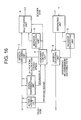
Fig. 16 is a block diagram for schematically representing an
entire arrangement of a DCME.
-
In Fig. 16, there are provided a active judging unit 1, a signal
discriminating unit 2, a speech (audio) encoding unit 3, an
assignment control unit 4, a message producing unit 5, a
multiplexing unit 6, a separating unit 7, a message decrypting unit
8, and a speech decoding unit 9. A left side of this drawing
corresponds to a trunk side through which plural channels of
telephone speech/voice band data in the 64 Kbit/s PCM (Pulse Code
Modulation) format are inputted/outputted. Also, a right side of
this drawing corresponds to a bearer side (transmit path side)
through which telephone speech /voice band data which have been
encoded in low bit rates (will be referred to as "encoded speech
signals" hereinafter) are transmitted/received.
-
For the sake of easy understandings, it is now assumed that
while this DCME owns as the trunk side a capacity capable of
inputting/outputting 600 channels of 64 Kbit/s-telephone
speech/voice band data signals, this DCME owns as the bearer side
a line capacity of 2 Mbit/s. Also, the following assumption is made
in the below-mentioned description:
-
As a encoding rate for a low-bit-rate speech encoding operation,
a encoding rate of 8 Kbit/s is used so as to transmit a telephone
speech signal, whereas another encoding rate of 40 Kbit/s is
employed in order to transmit a voice band data signal.
-
Next, a description will now be made of operations of the DCME
equipped with the arrangement shown in Fig. 16.
-
The 64 Kbit/s PCM-formatted signals for 600 channels, which
are entered from the trunk side of this DCME, are inputted into
the active judging unit 1, the signal discriminating unit 2, and
the speech encoding unit 3, respectively. The active judging unit
1 judges as to whether each of these 600 channels owns an active
signal, or a silent signal, and then outputs a judgement result
to the assignment control unit 4. The signal discriminating unit
2 judges as to whether an input signal of each trunk channel is
equal to a telephone speech (voice) signal, or a data signal such
as a facsimile signal, and then outputs this judgement result to
the assignment control unit 4.
-
Based upon both the active/silence judgement result of each
of the trunk channels derived from the active judging unit 1 and
also the speech/data discrimination result of each of the trunk
channels derived from the signal discriminating unit 2, the
assignment control unit 4 determines an assignment rate of each
trunk channel to the bearer circuit, and then outputs the determined
assignment result to both the message producing unit 5 and the
multiplexing unit 6.
-
As this bearer circuit assignment method, while trunk channels
having active signals are assigned to bearer circuits while priority
rights are given to these trunk channels, the encoding rate of 40
Kbit/s per one channel is assigned to such a trunk channel which
is judged as a data channel, and further the encoding rate of 8
Kbit/s per one channel is assigned to such a trunk channel which
is judged as a speech channel. The reason why the encoding rate
is changed in accordance with a sort of input signal is given as
follows: That is, the information amount compression principle of
the low-bit-rate speech encoding operation is to reduce redundancy
owned by a speech signal, while utilizing redundancy owned by the
speech signal. Although the high compression rate can be obtained
with respect to the speech signal, the high compression rate cannot
be obtained with respect to the voice band data signal such as the
facsimile signal.
-
The encoding rate of each of the trunk channels, which is
determined by this assignment control unit 4, is outputted to the
speech encoding unit 3, the speech encoding unit 3 is equipped with
speech decoding devices for 600 channels. In response to the
encoding rate information supplied from the assignment control unit
4, the speech encoding unit 3 encodes the input signals entered
from the respective trunk channels by 8 Kbit/s encoding rate when
these input signals are the telephone speech signals, and encodes
the input signals entered from the respective trunk channels by
40 Kbit/s encoding rate when these input signals are the voice band
data signals. Then, the speech encoding unit 3 outputs the encoded
signals to the multiplexing unit 6.
-
It should be noted that the assignment/no-assignment
information (namely, information as to whether or not each channel
is assigned to a bearer circuit) for the respective channels is
also entered from the assignment control unit 4 into the speech
encoding unit 3, the reason of which is given as follows:
-
Normally, both a speech coding device and a speech decoding
device are equipped with prediction filters for predicting spectrum
information of an input speech signal. The parameter of the
prediction filter provided in the speech decoding device which
constitutes the transmission side must be made coincident with the
parameter of the prediction filter provided in the speech decoding
device which constitutes the receiving side. In the case that this
prediction filter is such a type of algorithm for updating the past
parameter based upon a newly inputted speech signal, in order to
make the parameter of the encoding device coincident with the
parameter of the decoding device, when the encoding device is
connected to the decoding device (namely, when a bearer circuit
is newly assigned), both of these encoding/decoding devices are
required to be operated from such a condition that these parameters
thereof are initialized (reset). This operation is referred to as
"a synchronous reset" executed between the speech coding device
and the speech decoding device.
-
As a result, the speech encoding unit 3 may realize this
synchronous reset in such a manner that this speech encoding unit
3 initializes the above-explained parameters with respect to the
trunk channel operated under such a condition that the bearer has
been assigned based upon the assignment/no-assignment information
of the bearer circuit, which is changed from another trunk channel
condition where the bearer circuit is not assigned. Also, in the
speech decoding device, when input operation of the encoded signal
from the bearer circuit is commenced, the speech decoding device
initializes the parameter thereof.
-
The message producing unit 5 produces an assignment message
to be transmitted to an apparatus on the opposite side on the bearer,
based on an assignment result entered from the assignment control
unit 4.
-
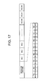
In this case, in order to explain the assignment message, Fig.
17 shows a structural example of a frame of a signal (DCME frame)
which is outputted by the DCME to the bearer circuit.
-
In this example, there are 248 channels of bearer channels
(BC) and a message channel. The speech encoded data is transmitted
via the bearer channels on the bearer circuit. The assignment
message is transmitted via the message channel on the bearer circuit.
Each of the BC channels owns a capacity of 8 Kbit/s, and therefore,
can transmit speech encoded data of 8 Kbit/s corresponding to 248
channels at maximum. Also, the speech encoded data of 40 Kbit/s
are transmitted by using 5 channels of the BC channels.
-
Normally, the length of this DCME frame is selected to be longer
than the 8 Kbit/s speech encoding frame length and the 40 Kbit/s
speech encoding frame length by an integer multiplication. For
example, in the case that the 8 Kbit/s speech encoding frame length
is equal to 10 ms and the 40 Kbit/s speech encoding frame length
is equal to 2.5 ms, the DCME frame length may be selected to be
10 ms. Subsequently, in this specification, assuming that this
length of the DCME frame is equal to 10 ms, the explanation is made
(bit number of each BC is equal to 10 ms x 8000 = 0.01 s x 8000
= 80 bits).
-
Also, 4 sets of messages are transmitted through the message
channel. A pair of a trunk channel number (TC number) and a bearer
channel number (BC number) may constitute 1 message. For instance,
when the number 5 of trunk channel is newly connected to the number
3 of bearer channel, such a message of TC number = 5 and BC number
= 3 is transmitted by employing one message. Normally in the case
that TC number = 0 indicates "remove", for example, when the trunk
channel connected to BC50 is removed, such a message of TC number
= 0 and BC number = 50 is transmitted.
-
As previously explained, the assignment message is used to
notify such assignment message to the apparatus on the opposite
side of the barer, namely how each of the trunk channels is assigned
to the bearer circuit. In order to save the capacity of the message
channel, only changing information about the assignment condition
is notified as this assignment message. As a consequence, in such
a case that there are large change amounts, for example, in the
case that a large number of trunk channels are transmitted from
silent states to active states at the same time, there is a certain
possibility that some channels would wait for assignments to bearer
circuits.
-
Based on the assignment result to the bearer circuit obtained
from the assignment control unit 4, the multiplexing unit 6
multiplexes the encoded signals of the respective trunk channels
derived from the speech encoding unit 3 to output the multiplexed
encoded signal to the bearer circuit. Also, this multiplexing unit
6 multiplexes the assignment messages entered from the message
producing unit 5 to output the multiplexed assignment message to
the bearer circuit.
-
Subsequently, a description will now be made of operations
of the DCME on the receiving side.
-
The separating unit 7 inputs thereinto both the encoded signal
derived from the bearer circuit and the signal on which the
assignment message is multiplexed, and then outputs the assignment
message to the message decrypting unit 8 and further outputs the
encoded signal to the speech decoding unit 9. It should be noted
that when the separating unit 7 separates the encoded signal, the
decrypt result of the assignment message is entered from the message
decrypting unit 8 so as to separate this encoded signal based upon
this decrypt result.
-
The message decrypting unit 8 inputs the assignment message
from the separating unit 7, and then outputs the message decrypt
result to the separating unit 7 and at the same time outputs both
the assignment/no-assignment information and the encoding rate
information of each of the trunk channels to the speech decoding
unit 9. The speech decoding unit 9 decodes the encoded signal
entered from the separating unit 7 based on the information entered
from the message decrypting unit 8 to thereby produce a PCM signal,
and then outputs this PCM signal to the respective channels provided
on the trunk side.
-
As previously explained, the DCME encodes the 64 Kbit/s PCM
signals supplied from the respective trunk channels by way of the
low-bit-rate encoding manner to obtain either the 8 Kbit/s PCM
signal or the 40 Kbit/s PCM signal. Furthermore, the DCME transmits
such a PCM signal with a top priority, which is judged as a "active"
PCM signal. As a consequence, this DCME can transmit the telephone
speech signal and the facsimile signal in a low-bit-rate.
-
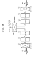
On the other hand, the following case will now be considered.
As shown in Fig. 18, such DCMEs are arranged at, for example, 3
points, and thus, a network structure is constituted.
-
Assuming now that the DCMEs are used in the international
telephone communication, these points "A", "B", and "C" correspond
to, for example, communication points in the respective countries
such as Japan, USA, and UK. In this network system of Fig. 18, when
a telephone communication is established between a telephone set
110 and a telephone set 111, a telephone communication signal
produced from the telephone set 110 is low-bit-rate encoded by the
DCME 100, and thereafter, this encoded telephone communication
signal is decoded by the DCME 101 to produce a PCM signal. This
PCM signal is transmitted via a exchange 106 to the DCME 102. In
this DCME 102, this PCM signal is again low-bit-rate encoded in
a low-bit-rate and then the encoded PCM signal is transmitted to
the DCME 103. In this DCME 103, this low-bit-rate encoded signal
is decoded to obtain a PCM signal which will then be supplied to
the telephone set 111.
-
As previously explained, when the DCMEs are used in such a
network structure as shown in Fig. 18, both the low-bit-rate
encoding operation and the decoding operation are repeated two times,
resulting in degradation of the telephone communication quality.
-
To avoid such a problem, such a technique called as "tandem
pass-through" has been practically used in the voice ATM
communication field and the like.
-
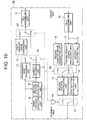
Fig. 19 is a structural diagram for indicating the voice ATM
transmission apparatus 60 equipped with the tandem pass-through
function disclosed in Japanese Laid-open Patent Application No.
Hei-10-190667.
-
In Fig. 19, reference numeral 10 shows a cell disassembling
unit for disassembling an ATM cell entered from a bearer circuit
side to output the disassembled ATM cell, reference numeral 9
represents a speech decoding unit for decoding a encoded signal
to output a PCM signal, reference numeral 3 indicates a speech
encoding unit for encoding the PCM signal inputted from the trunk
side to output a encoded signal, and reference numeral 11 shows
a cell assembling unit for assembling the entered encoded signals
to output an ATM cell. Also, reference numeral 12 is a pseudo speech
signal producing unit for converting either the 8 Kbit/s encoded
signal or the 40 Kbit/s encoded signal into such a 64 Kbit/s signal
which can be handled by the exchange without executing the decoding
operation to output a pseudo speech signal (for example, in case
of 8 Kbit/s encoded signal, dummy data of 56 Kbit/s is added to
this encoded signal so as to produce pseudo signal of 64 Kbit/s),
and reference numeral 13 shows a transmission rate recovering unit
for deleting the dummy data of 56 Kbit/s from the pseudo speech
signal inputted from the exchange side to convert this pseudo speech
signal into the encoded signal having the original encoding rate.
-
Also, reference numeral 14 indicates a second comfort noise
generating unit for generating comfort noise equivalent to
background noise during telephone conversation, reference numeral
15 shows a first comfort noise generating unit for generating
comfort noise equivalent to background noise during telephone
conversation, reference numeral 16 is a first pattern interpolating
unit for interpolating a second pattern signal used to cause a voice
ATM transmission apparatus as a counter-party apparatus during
relay operation to recognize a relay connection, reference numeral
17 is a second pattern interpolating unit for interpolating a first
pattern signal used to cause a voice ATM transmission apparatus
as a counter-party apparatus during relay operation to recognize
such a fact that the own voice ATM transmission apparatus detects
the first pattern signal to be brought into relay/switch condition,
reference numeral 18 is a first pattern detecting unit for detecting
the first pattern signal supplied from the voice ATM transmission
apparatus as the counter-party apparatus during relay operation,
and also, reference numeral 19 is a second pattern detecting unit
for detecting the second pattern signal supplied from the voice
ATM transmission apparatus as the counter-party apparatus during
relay operation.
-
Furthermore, reference numeral 20 shows a selector for
selectively switching the input signal from the speech encoding
unit 3, and the input signal from the transmission rate recovering
unit 13, reference numeral 21 indicates a selector for selectively
switching the input signal from the first pattern interpolating
unit 16 and the input signal from the pseudo speech signal producing
unit 12, reference numeral 22 indicates a selector for selectively
switching the input signal from the second comfort noise generating
unit 14 and the input signal from the pseudo speech signal producing
unit 12, reference numeral 23 represents a selector for selectively
switching the input signal from the first comfort noise generating
unit 15 and the input signal from the selector 20, and reference
numeral 24 shows an AND gate circuit for outputting "1" when either
one of the input signals derived from the first pattern detecting
unit 18 and the second pattern detecting unit 19 becomes "1", and
outputs "0", if not.
-
Next, assuming that the voice ATM transmission apparatus 60
equipped with the arrangement shown in Fig. 19 is applied to the
positions of the DCME 100, the DCME 101, the DCME 102, and the DCME
103 shown in Fig. 18, operations of this voice ATM transmission
apparatus will now be explained.
-
First, in the case that a telephone communication is
established between the telephone set 110 and the telephone set
112 in Fig. 18 (namely, when tandem connection is not made), a
description will now be made of operations in the case that the
voice ATM transmission apparatus 60 shown in Fig. 18 is installed
at the position of the DCME 101.
-
First of all, in Fig. 19, as the initial condition, the selector
21 selects the input signal from the first pattern interpolating
unit 16, the selector 20 selects the input signal from the speech
encoding unit 3, the selector 22 selects the input signal from the
pseudo speech signal generating unit 12, and the selector 23 selects
the input signal from the selector 20, respectively. It should be
noted that when the control input signal becomes "0", these
selectors 20, 21, 22, 23 select the input signals of the initial
condition side.
-
In the case that the telephone sets are not tandem-connected
by the exchange, both the first pattern detecting unit 18 and the
second pattern detecting unit 19 do not detect the first pattern
signal and the second pattern signal from the input signal of the
trunk side. As a result, the first and second pattern detecting
units 18 and 19 output "0" which may indicate that these pattern
detecting units 18/19 are not operated under detection states. As
a result, the operations of the selectors 20, 21, 22, and 23 are
not different from the initial conditions. As a consequence, the
speech signal path provided on the transmission side may constitute
such a path passing through the speech encoding unit 3, the selector
20, the selector 23, and the cell assembling unit 11. Also, the
speech signal path provided on the receiving side may constitute
such a path passing through the cell disassembling unit 10, the
speech decoding unit 9, the first pattern interpolating unit 16,
and the selector 21, so that the normal speech decoding operation
and the normal speech encoding operation are carried out.
-
Now, in the receiving-sided path, the first pattern
interpolating unit 16 interpolates the first pattern with respect
to the PCM speech signal outputted from the speech decoding unit
9. The PCM signal outputted from the speech decoding unit 9 may
become a signal of 64 Kbit/s. That is, this PCM signal corresponds
to a signal produced by that the speech signal waveform is sampled
every 125 microseconds, and then the amplitude of the sampled
waveform is quantized by 8 bits, namely 8/125 microseconds =
8/0.000125 = 64000. In order that the speech quality is not degraded
due to this pattern interpolation, the first pattern interpolating
unit 16 executes such an operation that only LSB contained in the
8-bit quantized value is bit-stolen every several sampling
operations so as to embed a specific pattern into this PCM signal.
As a result, even when the first pattern is interpolated, while
no adverse influence is given to the original PCM speech signal
waveform, the telephone communication can be carried out. The
voice ATM transmission apparatus located at the DCME 100 which is
connected via the bearer circuit to the DCME 101 as the counter-party
apparatus is operated in a similar manner to that of the DCME 101.
-
Next, a description will now be made of operations of such
voice ATM transmission apparatus arranged at the positions of the
DCME 101 and the DCME 102 in the case that the telephone sets are
relay-connected (tandem-connected) by the exchange, namely, in such
a case that a telephone communication is established between the
telephone set 110 and the telephone set 111 in Fig. 18.
-
Fig. 20 is a structural diagram for showing such a case that
exchange sides of voice ATM transmission apparatuses are
relay-connected. It should be noted that the same reference
numerals shown in Fig. 18 and Fig. 19 will be employed as those
for denoting the same, or similar circuit components indicated in
Fig. 20, and explanations thereof are omitted. In Fig. 20,
reference numerals 60B and 60C show two voice ATM transmission
apparatuses which constitute a pair, and are connected via a
exchange 106 to each other.
-
When such a connection is made by the exchange, as a first
stage, the first pattern detecting unit 18 employed in the voice
ATM transmission apparatus 60B detects the first pattern which is
interpolated by the first pattern interpolating unit 16 employed
in the voice ATM transmission apparatus 60C, and then outputs "1"
implying such a signal that the first pattern is detected. Also,
the second pattern detecting unit 18 employed in the voice ATM
transmission apparatus 60C detects the second pattern which is
interpolated by the second pattern interpolating unit 16 employed
in the voice ATM transmission apparatus 60B, and then outputs "1"
implying such a signal that the second pattern is detected. As a
consequence, the conditions of both the voice ATM transmission
apparatuses 60B and 60C are changed as follows: The output of the
AND gate circuit 24 becomes "1", the selector 21 selects/outputs
the input signal derived from the second pattern interpolating unit
17, the selector 22 selects/outputs the input signal derived from
the second comfort noise generating unit 14, and the selector 23
selects/outputs the input signal derived from the first comfort
noise generating unit 15. In the voice ATM transmission
apparatuses 60B and 60C operated under this condition, the signal
path provided on the receiving side may constitute the second
comfort noise generating unit 14, the selector 22, the second
pattern interpolating unit 17, and the selector 21, whereas the
signal path provided on the transmission side may constitute the
first comfort noise generating unit 15, the selector 23, and the
cell assembling unit 11.
-
In this case, the second comfort noise generating unit 14
outputs the comfort noise having the 64 Kbit/s PCM format. The
second pattern interpolating unit 17 interpolates the second
pattern with respect to the PCM signal outputted from the second
comfort noise generating unit 14. In order that this second pattern
can be discriminated from the above-explained first pattern, and
also does not give a large adverse influence to the outputs of the
comfort noise generating unit, the following operation is carried
out. For example, only second bit located at the lower bits of the
8-bit quantized value is bit-stolen every several sampling
operations with respect to the input PCM signal, and a specific
pattern is embedded. As previously explained, the voice ATM
transmission apparatuses 60B and 60C may output a silent PCM signal
into which the second pattern has been interpolated with respect
to the exchange side. Also, the first comfort noise generating unit
15 outputs either 8 Kbit/s encoded silent signal or the comfort
noise. As a result, the voice ATM transmission apparatuses 60B and
60C may also output either the silent signal or the comfort noise
with regard to the bearer circuit side.
-
At the next stage, such a silent PCM signal into which the
second pattern has been interpolated is entered from the exchange
side to the voice ATM transmission apparatuses 60B and 60C. As a
result, the second pattern detecting unit 19 detects the second
pattern in this silent PCM signal, and thus, outputs "1" indicative
of this pattern detection. As a consequence, the selector 20 selects
the input signal derived from the transmission rate recovering unit
13 to output the selected signal. Since the first pattern detecting
unit 18 does not detect the first pattern, this first pattern
detecting unit 18 outputs "0" indicative of no pattern detection.
As a result, the condition is changed in such a manner that the
selector 23 selects/outputs the input signal derived from the
selector 20, and the selector 22 selects/outputs the input signal
produced from the pseudo speech signal producing unit.
-
As to the state of the selector 21, since the output from the
AND gate circuit 24 maintains the state of "1" (since second pattern
is detected instead of first pattern), this selector 21 maintains
such a state that the input signal from the second pattern detecting
unit 17 is selected to be outputted. It should be noted that the
pseudo speech signal producing unit 12 produces the pseudo speech
signal of 64 Kbit/s by adding the dummy bit to the 8 Kbit/s encoded
signal entered from the cell disassembling unit. The second
pattern is interpolated to a portion of this pseudo speech signal
by the second pattern interpolating unit. In other words, the 8
Kbit/s encoded signal is outputted without any problem by assembling
the pseudo speech signal in such a way that a portion to be destroyed
may constitute a dummy bit. Since this pseudo speech signal is
inputted into the transmission rate recovering unit 13, the 8 Kbit/s
encoded signal is extracted from this pseudo speech signal to be
supplied to the selector 20.
-
When the apparatus is operated in accordance with the
above-explained manner, it can be seen that the pass-through
operation can be realized. In other words, in the voice ATM
transmission apparatus 60B, the encoded signal whose cells are
disassembled by the cell disassembling unit 10 is finally
transmitted to the cell assembling unit 11 of the voice ATM
transmission apparatus 60C, whereas to the contrary, in the voice
ATM transmission apparatus 60C, the encoded signal whose cells are
disassembled by the cell disassembling unit 10 is finally
transmitted to the cell assembling unit 11 of the voice ATM
transmission apparatus 60B.
-
If the above-described tandem pass-through function is applied
also to the DCME shown in Fig. 16, it is expectable that even when
the telephone speech signal is transmitted via a plurality of DCME
links, this telephone speech signal can be transmitted without
degrading the sound quality thereof.
-
However, when this tandem pass-through technique is applied
to a DCME, the below-mentioned problems occur.
-
For example, the following case will now be considered. That
is, in the Fig. 18, the tandem pass-through operation is realized
in the case that while a telephone communication is established
between the telephone set 110 and the telephone set 111, this
communication signal is transmitted through a single trunk channel
connected between the DCME 101 and the DCME 102.
-
In this case, the assignment of the bearer circuit from the
DCME 100 to the DCME 101 is changed, depending upon both the
active/silence state and the signal discrimination state, which
are detected in the DCME 100. For example, when the telephone
communication signal produced from the telephone set 100 becomes
silent (silent), the connection between the bearer circuit and this
trunk channel along the direction defined from the DCME 100 to the
DCME 101 may be removed. This information on bearer assignment may
be notified by embedding the active/silence information into the
pseudo speech signal which is transmitted from the DCME 101 to the
DCME 102. Then, the DCME 102 may determine the assignments of this
trunk channel to the bearer circuit based upon the active/silence
information embedded in this pseudo speech signal.
-
However, when the bearer circuit is assigned, such a channel
operated under silent state is searched from the trunk channels
under connection with the bearer circuit, and thereafter, the bearer
circuit assignment must be rearranged. Assuming now that all of
the trunk channels connected to the bearer circuits are operated
under active states, the bearer circuit assignments of a trunk
channel witch newly become under active state may be waited. When
the bearer circuit assignment is brought into the waiting state,
a portion of the "active" speech signal is dropped, and therefore,
a so-called "freeze out" phenomenon will occur. In general, if the
time rate of the "freeze out" phenomenon occurs with respect to
the entire active time, namely freeze out fraction ratio is smaller
than, or equal to 0.5 percents, substantially no detection can be
made of degradations in telephone communications.
-
However, when such a freeze out phenomenon occurs in the trunk
channel operated under tandem pass-through connection, not only
a portion of the speech signal is dropped out, but also another
problem may be newly produced. That is, the speech coding device
and the speech decoding device cannot be reset in the synchronous
resetting mode. It should also be noted that such a freeze out
phenomenon may be produced by limiting a total number of messages.
-
As previously explained, when the synchronous resetting
operation cannot be realized between the speech coding device and
the speech decoding device, the internal parameters of both devices
are not made coincident with each other. As a result, degradations
of the telephone communication quality may be considerably induced.
-
Furthermore, a similar inconvenient case may occur in such
a case that the speech encoding rate is changed, due to the change
in the speech/data discrimination state, and thus, the bearer
circuit assignment rate is changed.
-
For instance, considering now such a condition that the bearer
circuit assignment rate from the DCME 100 to the DCME 101 is changed
from 8 Kbit/s to 40 Kbit/s, the tandem pass-through function may
be expectedly realized when the following operation is basically
carried out. That is, similar to the active/silence information,
while the encoding rate information is embedded in the pseudo speech
signal, the bearer circuit assignment is determined based on this
information in the DCME 102.
-
However, in such a case that a change in the bearer circuit
assignment rate is brought into a waiting state in the DCME 102
due to a lack of total bearer circuit capacity to be assigned and
also a limitation in total message number, such a problem may occur
in which in this trunk channel, there is no signal to be outputted
to the bearer circuit (namely, bearer circuit assignment is selected
to be 8 Kbit/s whereas encoded data extracted from pseudo speech
signal is 40 Kbit/s). As a result, while such a problem is continued,
a certain invalid signal should be necessarily outputted to the
DCME 103. As a consequence, there is a certain possibility that
extraordinary sounds may be reproduced from the speech decoding
device in the DCME 103.
-
Also, when the bearer circuit assignment rate is changed into
40 Kbit/s after a certain time period has passed, since the encoded
data are lost by such a data quantity corresponding to the waiting
time period for the assignment change, the internal parameter of
the speech decoding device employed in the DCME 100 is not made
coincident with the internal parameter of the speech decoding device
employed in the DCME 103, resulting in degradation in the telephone
communication quality.
-
As described above, in the conventional technique, when the
tandem pass-through function is attempted to be installed in DCME,
the bearer circuit assignment change is delayed, with the result
that a speech coding device and a speech decoding device can not
be reset in a synchronous resetting mode in DCME provided on both
ends of the transmission path, which causes disagreement of the
internal parameter thereof, and arises a problem of degradation
in the telephone communication quality
SUMMARY OF THE INVENTION
-
The present invention has been made to solve the problems of
the prior art, and therefore, has an object to provide such a digital
circuit multiplication equipment equipped with a tandem pass-through
function, by which a speech coding device and a speech
decoding device can be reset in a synchronous resetting mode.
-
In a digital circuit multiplication equipment equipped with
a tandem pass-through function capable of passthrough-transmitting
a signal with respect to a trunk channel repeated/connected thereto
via a exchange, while not performing both a low-bit-rate speech
encoding operation and also a low-bit-rate speech decoding
operation, the digital circuit multiplication equipment according
to an aspect of the invention comprises means for transmitting
(notifying) the number of trunk channel operated under pass-through
operation to another digital circuit multiplication equipment
connected via a bearer circuit and means for continuously assigning
a bearer circuit with respect to the number of trunk channel number
operated under pass-through operation.
-
Also, it is characterized in that said means for transmitting
(notifying) the number of said trunk channel operated under
pass-through operation to another digital circuit multiplication
equipment connected thereto via the bearer circuit transmits
(notifies) the trunk channel number by employing a specific bearer
channel number contained in an assignment message of a bearer
circuit.
-
Further, it is characterized in that said means for
transmitting (notifying) the number of said trunk channel operated
under pass-through operation to another digital circuit
multiplication equipment connected thereto via the bearer circuit
transmits (notifies) the trunk channel number by employing a
specific bearer channel number contained in an assignment message
of a bearer circuit.
-
Furthermore, in a digital circuit multiplication equipment
equipped with a tandem pass-through function capable of
passthrough-transmitting a signal with respect to a trunk channel
repeated/connected thereto via a exchange, while not performing
both a low-bit-rate speech encoding operation and also a low-bit-rate
speech encoding operation, the digital circuit
multiplication equipment according to another aspect of the
invention comprises means for continuously assigning a trunk
channel operated under pass-through operation to a bearer circuit.
-
Still further, in a digital circuit multiplication equipment
equipped with a tandem pass-through function capable of
passthrough-transmitting a signal with respect to a trunk channel
repeated/connected thereto via a exchange, while not performing
both a low-bit-rate speech encoding operation and also a low-bit-rate
speech encoding operation, the digital circuit
multiplication equipment according to a further aspect of the
invention comprises means for embedding information into a signal
which is outputted with respect to a trunk channel operation under
pass-through operation, said information indicating as to whether
or not a encoded speech signal derived from a bearer circuit is
present, means for detecting from an input signal of a trunk channel
operated under pass-through operation, information indicating as
to whether or not said encoded speech signal derived from said bearer
circuit is present, means for outputting a first invalid encoded
signal indicative of being equal to an invalid encoded signal with
respect to the bearer circuit in such a case that the encoded speech
signal derived from the bearer circuit is not contained in the input
signal of the trunk channel operated under the pass-through
operation, a speech decoding device for outputting only a signal
different from said first invalid encoded signal, and means for
outputting a silent (silent) PCM signal in a trunk channel which
receives said first invalid encoded signal from the bearer circuit.
-
Yet still further, in a digital circuit multiplication
equipment equipped with a tandem pass-through function capable of
passthrough-transmitting a signal with respect to a trunk channel
repeated/connected thereto via a exchange, while not performing
both a low-bit-rate speech encoding operation and also a low-bit-rate
speech encoding operation, the digital circuit
multiplication equipment according to an additional aspect of the
invention comprises means for synthesizing a first invalid encoded
signal which indicates that in a trunk channel operated under
pass-through operation, where an input signal from a bearer circuit
is not supplied, a encoded signal thereof is invalid with an output
signal of said trunk channel a speech decoding device for outputting
only a signal different from a signal for indicating that the encoded
signal is invalid with respect to said bearer circuit and means
for outputting a silent PCM signal in a trunk channel for receiving
said first invalid encoded signal from the bearer circuit.
-
Furthermore, it is characterized in that said digital circuit
multiplication equipment is further comprises means for determining
an assignment of the trunk channel operated under pass-through
operation to the bearer circuit by employing such information for
indicating as to whether or not a encoded speech signal derived
from the bearer circuit is present in the input signal of the trunk
channel and means for delaying a encoded signal contained in an
input signal of a trunk channel in such a case that when a state
under which the encoded speech signal is not present from the bearer
circuit contained in the input signal of the trunk channel operated
under pass-through operation is transmitted to another state under
which the encoded speech signal is present, the assignment of said
trunk channel to the bearer circuit is delayed, and for starting
to output said delayed encoded signal after the trunk channel has
been assigned to the bearer circuit.
-
In addition, it is characterized in that said digital circuit
multiplication equipment is further comprise means for outputting
encoded speech signals which correspond to plural frames and have
been inputted from the bearer circuit in the past with respect to
the trunk channel operated under pass-through operation, means for
extracting said encoded speech signal corresponding to the plural
frames from the input signal of the trunk channel operated under
pass-through operation and means for outputting old encoded speech
signals by the delayed assignment number from the encoded speech
signals corresponding to the plural frames, which are extracted
from the input signal of said trunk channel in such a case that
when a state under which the encoded speech signal is not present
from the bearer circuit contained in the input signal of the trunk
channel operated under pass-through operation is transmitted to
another state under which the encoded speech signal is present,
the assignment of said trunk channel to the bearer circuit is delayed,
and for starting to output said delayed encoded signal after the
trunk channel has been assigned to the bearer circuit.
-
Still further, it is characterized in that said digital circuit
multiplication equipment is further comprises means for embedding
information indicative of a encoding rate of a encoded speech signal
from the bearer circuit into a signal which is outputted with respect
to a trunk channel operated under pass-through operation, means
for detecting the information indicative of said encoding rate from
the input signal of the trunk channel operated under pass-through
operation, means for determining an assignment of said trunk channel
to the bearer circuit by using said encoding rate detected from
the input signal of the trunk channel operated under pass-through
operation, and means for delaying the encoded signal contained in
the input signal of the trunk channel in such a case that when the
encoding rate of the encoded speech signal contained in the input
signal of the trunk channel operated under pass-through operation
is transmitted, the assignment rate change of said trunk channel
to the bearer circuit is delayed, and for starting to output the
delayed encoded signal after the bearer circuit assignment rate
has been changed.
-
Yet still further, it is characterized in that said digital
circuit multiplication equipment is further comprises means for
outputting a second invalid encoded signal to the bearer circuit
until the assignment rate to the bearer circuit is changed, said
second invalid encoded signal indicating that said signal is an
invalid encoded speech signal, in such a case that when the encoding
rate of the encoded speech signal contained in the input signal
of the trunk channel operated under pass-through operation is
transmitted, the assignment rate change of said trunk channel to
the bearer circuit is delayed, a speech decoding device for
outputting only such a signal different from both said first invalid
encoded signal and said second invalid encoded signal, and means
for outputting a silent PCM signal in the case that said first
invalid encoded signal is entered from the bearer circuit, and also
for outputting a prediction PCM signal for predicting a PCM signal
which should be subsequently outputted in such a case that said
second invalid encoded signal is inputted.
-
Moreover, it is characterized in that said digital circuit
multiplication equipment is further comprises means for embedding
information indicative of a encoding rate of a encoded speech signal
from the bearer circuit into a signal which is outputted with respect
to a trunk channel operated under pass-through operation, means
for detecting the information indicative of said encoding rate from
the input signal of the trunk channel operated under pass-through
operation, means for determining an assignment of said trunk channel
to the bearer circuit by using said encoding rate detected from
the input signal of the trunk channel operated under pass-through
operation, means for delaying the encoded signal contained in the
input signal of the trunk channel in such a case that when the
encoding rate of the encoded speech signal contained in the input
signal of the trunk channel operated under pass-through operation
is transmitted from a low rate to a high rate, the assignment rate
change of said trunk channel to the bearer circuit is delayed, and
for starting to output the delayed encoded signal after the
assignment rate the bearer circuit has been changed, means for
outputting a second invalid encoded signal to the bearer circuit
until the assignment rate to the bearer circuit is changed, said
second invalid encoded signal indicating that said signal is an
invalid encoded speech signal, in such a case that when the encoding
rate of the encoded speech signal contained in the input signal
of the trunk channel operated under pass-through operation is
transmitted from the low rate to the high rate, the assignment rate
change of said trunk channel to the bearer circuit is delayed, means
for synthesizing the encoded signal contained in the input signal
of said trunk channel with such information for indicating such
a fact that the encoded signal of the lower encoding rate is
contained in the case that when the encoding rate of the encoded
speech signal contained in the input signal of the trunk channel
operated under pass-through operation is transferred from a high
rate to a low rate, the assignment rate change of said trunk channel
to the bearer circuit is delayed, and then for outputting the
synthesized encoded signal to the bearer circuit, a speech decoding
device for outputting only such a signal different from both said
first invalid encoded signal and said second invalid encoded signal,
and means for outputting a silent PCM signal in the case that said
first invalid encoded signal is entered from the bearer circuit,
and for outputting a prediction PCM signal for predicting a PCM
signal which would be subsequently outputted in such a case that
said second invalid encoded signal is inputted; and further for
extracting the encoded signal of the low rate to be decoded into
a PCM signal in such a case that such a signal is inputted in which
said encoded signal of the low rate is synthesized with the
information for indicating that the encoded signal of the low rate
is contained.
-
Still, it is characterized in that when a speech encoding
system corresponds to the ADPCM system defined in the ITU-T
recommendation G.726, a encoded signal which is not defined by said
ITU-T recommendation and contains such encodes, all of which for
1 sample are equal to "1", is used as said first invalid encoded
signal.
-
Further still, it is characterized in that when a speech
encoding system corresponds to the CELP system, a encoded signal
containing a vector is used as said first invalid encoded signal,
the use frequency of which vector being low when a speech signal
is inputted into the encoding device.
-
In addition, it is characterized in that when a speech encoding
system corresponds to the ADPCM system defined in the ITU-T
recommendation G.726, a encoded signal which contains such encodes,
all of which for 1 sample are equal to "1", which is not defined
by said ITU-T recommendation, is used as said second invalid encoded
signal.
-
Finally, it is characterized in that when a speech encoding
system corresponds to the CELP system, a encoded signal containing
a vector is used as said second invalid encoded signal, the use
frequency of which vector being low when a speech signal is inputted
into the encoding device.
BRIEF DESCRIPTION OF THE PREFERRED EMBODIMENTS
-
For a better understanding of the present invention, reference
is made of a detailed description to be read in conjunction with
the accompanying drawings, in which:
- Fig. 1 is a schematic block diagram for showing an entire
arrangement of a digital circuit multiplication equipment (DCME)
according to an embodiment mode 1 of the present invention;
- Fig. 2 is a schematic block diagram for representing an entire
arrangement of a digital circuit multiplication equipment (DCME)
according to an embodiment mode 3 of the present invention;
- Fig. 3 is a schematic block diagram for indicating an internal
arrangement of the transmission rate recovering unit 13 shown in
Fig. 2;
- Fig. 4 is a schematic block diagram for showing an internal
arrangement of the speech decoding unit 9 shown in Fig. 2;
- Fig. 5 is a schematic block diagram for showing an entire
arrangement of a digital circuit multiplication equipment (DCME)
according to an embodiment mode 13 of the present invention;
- Fig. 6 is a schematic block diagram for representing an entire
arrangement of a digital circuit multiplication equipment (DCME)
according to an embodiment mode 14 of the present invention;
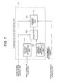
- Fig. 7 is a schematic block diagram for indicating an internal
arrangement of the transmission rate recovering unit 13 shown in
Fig. 6;
- Fig. 8 is a schematic block diagram for showing an internal
arrangement of the pseudo speech signal producing unit 12 employed
in a digital circuit multiplication equipment according to an
embodiment mode 15 of the present invention;
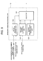
- Fig. 9 is a schematic block diagram for indicating an internal
arrangement of the transmission rate recovering unit 13 employed
in the digital circuit multiplication equipment according to the
embodiment mode 15 of the present invention;
- Fig. 10 is a schematic block diagram for showing an entire
arrangement of a digital circuit multiplication equipment (DCME)
according to an embodiment mode 16 of the present invention;
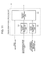
- Fig. 11 is a schematic block diagram for indicating an internal
arrangement of the pseudo speech signal producing unit 12 shown
in Fig. 10;
- Fig. 12 is a schematic block diagram for showing an internal
arrangement of the transmission rate recovering unit 13 shown in
Fig. 10;
- Fig. 13 is a schematic block diagram for indicating an internal
arrangement of the speech decoding unit 9 employed in a digital
circuit multiplication equipment according to an embodiment mode
17 of the present invention;
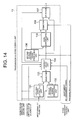
- Fig. 14 is a schematic block diagram for indicating an internal
arrangement of the transmission rate recovering unit 13 employed
in a digital circuit multiplication equipment according to an
embodiment mode 18 of the present invention;
- Fig. 15 is a schematic block diagram for showing an internal
arrangement of the speech decoding unit 9 of the digital circuit
multiplication equipment of the embodiment mode 18;
- Fig. 16 is a schematic block diagram for showing the entire
arrangement of the conventional digital circuit multiplication
equipment (DCME);
- Fig. 17 is a frame (DCME frame) structural diagram of the signal
outputted by the digital circuit multiplication equipment (DCME)
to the bearer circuit;
- Fig. 18 is a schematic diagram for schematically indicating
the network in which the digital circuit multiplication equipmentes
(DCME) are arranged at three points;
- Fig. 19 is a schematic diagram for schematically showing the
voice ATM transmission apparatus 60 equipped with the tandem
pass-through function, disclosed in Japanese Laid-open Patent
Application No. Hei-10-190667; and
- Fig. 20 is a schematic diagram for schematically representing
such a case that the switching-unit-sided terminal of the voice
ATM transmission apparatus is connected.
-
DETAILED DESCRIPTION OF THE PREFERRED EMBODIMENTS
EMBODIMENT MODE 1
-
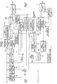
Fig. 1 is a block diagram for schematically representing an
entire arrangement of a digital circuit multiplication equipment
(DCME) according to an embodiment mode 1 of the present invention.
-
It should be noted that the same reference numerals shown in
Fig. 16, Fig. 19, and Fig. 20 will be employed as those for denoting
the same, or the same circuit units indicated in Fig. 1, and
explanations thereof are omitted. In Fig. 1, newly employed
reference numerals are given as follows: That is, reference numeral
25 indicates an AND gate circuit, reference numeral 26 represents
an OR gate circuit, and reference numeral 27 indicates a pass-through
notifying message generating unit. The pass-through
notifying message generating unit 27 generates a message used to
notify a trunk channel operated under pass-through operation to
a DCME on the opposite side of the bearer functioning as a
counter-party apparatus.
-
Next, operations of the digital circuit multiplication
equipment (will be simply referred to as a "DCME" hereinafter).
indicated in Fig. 1 will be described.
-
In Fig. 1, a active judging unit 1, a signal discriminating
unit 2, a speech (audio) encoding unit 3, an assignment control
unit 4, a multiplexing unit 6, a separating unit 7, a message
decrypting unit 8, and also a speech (audio) decoding unit 9 are
operated in a similar manner to those of the DCME indicated in Fig.
16. In addition to the operation of the DCME shown in Fig. 16, a
new operation required to realize a pass-through operation is
additionally provided with this message decrypting unit 8 which
will be described later. It should also be noted that each of the
below-mentioned circuit blocks performs a plurality of functional
operations, a total number of which is equal to a total number of
trunk channels stored in the DCME, namely plural functional
operations for 600 channels. These functional operations are
independently carried out every channel. The functional
operations for one channel are carried out in a similar manner to
those of the circuit block having the same reference numerals in
the voice ATM transmission apparatus shown in Fig. 19. These
circuit blocks are a pseudo speech signal producing unit 12, a
transmission rate recovering unit 13, a second comfort noise
generating unit 14, a first comfort noise unit 15, a first pattern
interpolating unit 16, a second pattern interpolating unit 17, a
first pattern detecting unit 18, a second pattern detecting unit
19, a selector 20, a selector 21, a selector 22, a selector 23,
and an OR gate circuit 24.
-
In this case, a description will now be made of operations
in the following case. That is, in Fig. 18, while a telephone
communication is established between a telephone set 100 and another
telephone set 110, a trunk channel number "n" (TCn) of a DCME 101
and a trunk channel number "n" (TCn) of another DCME 102 are
repeated/connected by a exchange 106. It should also be noted that
each of the respective circuit blocks except for the below-mentioned
circuit blocks shown in Fig. 1 performs a plurality of functional
operations, a total number of which is equal to a total number of
trunk channels stored in the DCME, namely plural functional
operations for 600 channels in a parallel manner. These functional
operations are independently carried out every channel. The
functional operations for one channel are carried out in a similar
manner with each other. As a consequence, it is now assumed that
all of the below-mentioned operation explanations as to all of these
circuit blocks are given to the trunk channel number "n" (TCn).
These circuit blocks are the assignment control unit 4, the message
producing unit 5, the multiplexing unit 6, the separating unit 7,
the message decrypting unit 8, and the pass-through notifying
message generating unit 27.
-
In the DCME 101, the second pattern detecting unit 19 detects
a second pattern from a PCM (pulse code modulation) signal inputted
from the trunk side, and then sets an output control signal to "1."
As a result, since the control signal entered from the second pattern
detecting unit 19 is equal to "1", the OR gate circuit 26 outputs
"1" as an output control signal with respect to the assignment
control circuit 4 irrespective of an input signal derived from the
active judging unit 1. This output control signal of "1" indicates
that a sound is present.
-
Also, the pass-through notifying message generating unit 27
generates a message when the control signal input of the trunk
channel number TCn supplied from the second pattern detecting unit
19 is "1". This generated message is to notify to the counter-party
DCME 100 on the opposite side of the bearer, such a fact that
the trunk channel number TCn commences the pass-through operation.
The pass-through notifying message generating unit 27 transmits
this message from the multiplexing unit 6 via the bearer circuit
to the DCME 100 connected opposite thereto.
-
As previously explained with reference to Fig. 17, a single
message is made by combining a trunk channel number (TC number)
with a bearer channel number (BC number). Since the bearer channel
numbers under use are defined from 1 to 248, a bearer channel number
(BC number) "249" is used as a pass-through operation
starting-message. For instance, such a message that TC number =
n and BC number = 249 implies that the trunk channel number "TCn"
commences the pass-through operation. Also, a bearer channel
number BC number = 250 implies a pass-through operation ending
message. When the control signal of the trunk channel number TCn
derived from the second pattern detecting unit 19 is changed from
"1" into "0", the pass-through notifying message generating unit
27 outputs the pass-through operation ending message.
-
It should also be noted that the encoding rate information
of each of the trunk channels which is outputted from the message
decrypting unit 8 to the speech decoding unit 9 is also entered
into the AND gate circuit 25. In this case, as this encoding rate
information, when the encoding rate of the relevant trunk channel
is equal to 40 Kbit/s, a control signal of "0" is outputted whereas
when the encoding rate of the relevant trunk channel is equal to
8 Kbit/s, a control signal of "1" is outputted. As a consequence,
if the encoding rate of the trunk channel number TCn is equal to
8 Kbit/s, since the control signal of TCn outputted from the message
decrypting unit 8 becomes "1", the output signal outputted from
the AND gate circuit 25 is identical to the input signal derived
from the OR gate circuit 24. As a result, the AND gate circuit 25
gives no adverse influence to the selection operation of the
selector 12.
-
Conversely, if the encoding rate of the trunk channel number
TCn is equal to 40 Kbit/s, since the control signal of TCn outputted
from the message decrypting unit 8 becomes "0", the output signal
outputted from the AND gate circuit 25 is continuously identical
to "0" , so that the selector 21 continuously selects the input signal
supplied from the first pattern interpolating unit 16 to output
this selected input signal to the exchange side. This operation
implies that the pass-through operation is not carried out.
-
As explained above, the AND gate circuit 25 may have such a
function that the pass-through operation is not carried out with
respect to the trunk channel through which the voice-band data is
transmitted.
-
On the other hand, in the DCME 100 shown in Fig. 18, when the
message decrypting unit 8 recognizes that the message indicative
of starting of the pass-through operation of TCn is received from
the DCME 101 on the opposite side of the bearer functioning as the
counter-party apparatus, this message decrypting unit 8 sets the
output control signal of TCn to "1" with respect to the OR gate
circuit 26. It should be noted that in the DCME 101 on the opposite
side of the bearer functioning as the counter-party apparatus, the
output control signal to the OR gate circuit 26 becomes "0" as to
such a trunk channel TC which is not operated under pass-through
operation (namely, DCME 101 does not receive such a message of
starting of pass-through operation). When the control signal
supplied from the message decrypting unit 8 is equal to "1", the
OR gate circuit 26 outputs "1" as the output control signal to the
assignment control unit 4 irrespective of the input signal derived
from the active judging unit 1. This output control signal of "1"
indicates that a sound is present.
-
It should be understood that the operation of the DCME 102
is carried out in completely the same manner to that of the DCME
101, and also the operation of the DCME 103 is carried out in
completely the same manner to that of the DCME 100 in Fig. 18.
-
Then, when the DCMEs are operated in the above-described manner,
in both the DCME 101 and the DCME 102 shown in Fig. 18, as to the
trunk channel repeated/connected by the exchange 106, neither the
speech encoding operation, nor the speech decoding operation is
performed. However, the assignment to the bearer circuits is
continuously carried out in order that the trunk channel is not
only operated as the pass-through operation, but also is always
recognized as the sound channel. Also, as to the DCME 100 connected
opposite to the DCME 101 and also the DCME 103 connected opposite
to the DCME 102, the bearer circuits of the trunk channels operated
under tandem pass-through operation in the DCME 101 and the DCME
102 are continuously assigned to the bearer circuits. It should
also be noted that this channel assignment is only limited to such
a case that the encoding rate is selected to be 8 Kbit/s. Conversely,
when the encoding rate is selected to be 40 Kbit/s, since the second
pattern interpolation is not carried out, the pass-through
operation is also not carried out. In other words, since there is
no change in the assignment operation of the bearer circuits with
respect to the trunk channel operated under tandem pass-through
operation, the following problem never occurs. That is, the
synchronous resetting operations of the speech decoding device and
also of the speech decoding device cannot operate properly. As a
consequence, the tandem pass-through function can be realized
without degrading the telephone communication quality.
EMBODIMENT MODE 2
-
In the above-described embodiment mode 1, the pass-through
operation starting/ending message are produced by employing the
unused bearer channel number BC. Alternatively, an unused trunk
channel number TC may be employed so as to produce such pass-through
operation starting/ending messages. For instance, since a total
number of trunk channels stored in the DCME is equal to 600 channels,
the TC numbers = 601 and 602 are not used as the bearer circuit
assignment message. As a consequence, even when such a message that
the TC number = 601 and the BC number = m indicates that the trunk
channel presently connected to m-th BC starts the pass-through
operation, whereas such a message that the TC number = 602 and the
BC number = m indicates that the trunk channel presently connected
to the m-th BC ends the pass-through operation, a similar operation
to that of the above-explained embodiment mode 1 can be realized.
EMBODIMENT MODE 3
-
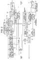
Fig. 2 is a block diagram for schematically representing an
entire arrangement of a digital circuit-multiplication equipment
(DCME) according to an embodiment mode 3 of the present invention.
It should be noted that the same reference numerals shown in the
embodiment mode 1 of Fig. 1 will be employed as those for indicating
the same, or similar circuit units represented in Fig. 2, and
explanations thereof are omitted. As a newly employed reference
numeral, reference numeral 28 shows a pseudo speech active judging
unit for judging as to whether a encoded signal is contained in
a pseudo speech (audio) signal outputted from a pseudo speech signal
producing unit 12.
-
Next, operations of the digital circuit multiplication
equipment (will be simply referred to as a "DCME" hereinafter)
indicated in Fig. 2 will be described.
-
In Fig. 2, a active judging unit 1, a signal discriminating
unit 2, a speech (audio) encoding unit 3, an assignment control
unit 4, a multiplexing unit 6, a separating unit 7, a second comfort
noise generating unit 14, a first comfort noise unit 15, a first
pattern interpolating unit 16, a second pattern interpolating unit
17, a first pattern detecting unit 18, a second pattern detecting
unit 19, a selector 20, a selector 21, a selector 22, a selector
23, also an OR gate circuit 24, and an AND gate circuit 25 are operated
in a similar manner to those of the DCME shown in Fig. 1. The message
decrypting unit 9 is operated in a similar manner to that of the
DCME shown in Fig. 16. In addition to similar operations to those
of the DCME shown in Fig. 1, the speech encoding unit 3, the speech
decoding unit 9, and the transmission rate recovering unit 13 are
operated with new operation manners (will be explained later).
-
Similar to the explanation of the operations by the DCME shown
in Fig. 1, in Fig. 18, while a telephone communication is established
between a telephone set 100 and another telephone set 110, a trunk
channel number "n" (TCn) of a DCME 101 and a trunk channel number
"n" of another DCME 102 are repeated/connected by a exchange 106
(namely trunk channel numbers TCn in DCME 100 and DCME 103 are also
used in telephone communication between telephone 100 and telephone
110). It should also be noted that each of the respective circuit
blocks except for the below-mentioned circuit blocks shown in Fig.
2 performs a plurality of functional operations, a total number
of which is equal to a total number of trunk channels stored in
the DCME in a parallel manner. These functional operations are
independently carried out every channel. The functional
operations for one channel are carried out in a similar manner with
each other. As a consequence, it is now assumed that all of the
below-mentioned operation explanations as to all of these circuit
blocks are given to the trunk channel number "n" (TCn). These
circuit blocks are the assignment control unit 4, the message
producing unit 5, the multiplexing unit 6, the separating unit 7,
and the message decrypting unit 8.
-
Similar to the DCME shown in Fig. 1, in the DCME 101 and the
DCME 102, the selector 22 selects the input signal supplied from
the pseudo speech signal producing unit 12, and the selector 21
selects the input signal supplied from the second pattern
interpolating unit 17, the selector 20 selects the input signal
supplied from the transmission rate recovering unit 13, and further
the selector 23 selects the input signal derived from the selector
20 to output this selected signal. As a result, it is apparent that
the trunk channel number TCn is operated under pass-through
operation. Since the DCME shown in Fig. 2 does not contain the
pass-through notifying message producing unit 27 existed in the
DCME of Fig. 1, even when the trunk channel number TCn is operated
under pass-through operation, there are some cases that the TCn
is not assigned to the bearer circuit in the DCMEs (DCME 100 and
DCME 103) located at both ends in Fig. 18. This implies such a case
that there is no input signal supplied from the bearer circuit even
for the TCn operated under pass-through operation in the DCME 101
and the DCME 102 shown in Fig. 18.
-
As a result, the pseudo speech signal producing unit 12 is
operated as follows: The active/silence information is added to
the encoded signal of 8 Kbit/s entered from the separating unit
7, and dummy data is further added thereto, so that such a pseudo
speech signal of 64 Kbit/s may be outputted from this pseudo speech
signal producing unit 12. As the above-explained active/silence
information, when the encoded signal of 8 Kbit/s is not inputted
from the separating unit 7, "silent" information is outputted,
whereas when the encoded signal of 8 Kbit/s is inputted therefrom,
"active" information is outputted, while these "silent" information
and "active" information are contained in the pseudo speech signal.
-
Next, the pseudo speech active judging unit 28 employed in
the DCME 101 detects the above-explained active/silent information
contained in the pseudo speech signal outputted from the pseudo
speech signal producing unit 12 in DCME 102. When the active
information is contained in the pseudo speech signal, the pseudo
speech active judging unit 28 outputs "1" as a control signal to
the transmission rate recovering unit 13. Conversely, when the
silent information is contained in the pseudo speech signal, the
pseudo speech active judging unit 28 outputs "0" as a control signal
to the transmission rate recovering unit 13. The operation of this
transmission rate recovering unit 13 will now be explained with
reference to Fig. 3 which shows an internal arrangement of the
transmission rate recovering unit 13.
-
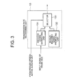
That is, Fig. 3 is a block diagram showing the internal
arrangement of the transmission rate recovering unit 13.
-
In Fig. 3, a encoded signal extracting unit 131 extracts the
encoded signal of 8 Kbit/s from the entered pseudo speech signal
to output the extracted encoded signal to the selector 133. Also,
an invalid encoded signal producing unit 132 outputs such a encoded
signal of 8 Kbit/s for indicating that this signal is invalid (will
be referred to as an "invalid encoded signal" hereinafter). The
encoded signal of 8 Kbit/s owns 80 bits per 1 DCME frame. For
instance, this encoded signal may be defined as such a signal which
represents that a signal whose all 80 bits are equal to "1" is
invalid.
-
Also, both the speech encoding unit 3 and the first comfort
noise generating unit 15 output encoded signals of 8 Kbit/s, whose
all 80 bits are not necessarily equal to "1." The speech encoding
algorithm is generally used CELP (Code Excited Linear Prediction)
algorithm. In this CELP system, it is easy not to output such a
signal whose all 80 bits become "1" based upon the following method.
That is, since a specific parameter is vector-quantized and the
code of this vector is contained in the code of this CELP system,
such a vector whose all bits are equal to "1" is not previously
used.
-
If the control signal supplied from the pseudo speech active
judging unit 28 is equal to "1", then a selector 133 selects the
output of the encoded data extracting unit 131 to output this
selected data. If the control signal is equal to "0", then this
selector 133 selects the output of the invalid encoded signal
producing unit 132.
-
As a result, the operation of the transmission rate recovering
unit 13 is carried out in accordance with the following manner.
That is, in such a case that the active/silence information
contained in the pseudo speech signal to be inputted is the active
information, namely the speech encoded signal is actually contained
in this pseudo speech signal, the transmission rate recovering unit
13 derives this speech encoded signal to be outputted. To the
contrary, in such a case that the active/silence information
contained in the pseudo speech signal to be inputted is the silent
information, namely the speech encoded signal is not actually
contained in this pseudo speech signal, the transmission rate
recovering unit 13 derives this invalid encoded signal to be
outputted.
-
The signal outputted from the above-described transmission
rate recovering unit 13 is entered into the speech decoding unit
9 employed in the DCME (when this output signal is signal outputted
from transmission rate recovering unit 13 employed in DCME 101,
DCME 100 corresponds thereto) connected as the counter-party
apparatus via the bearer circuit.
-
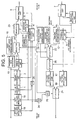
Fig. 4 is a block diagram for indicating an internal
arrangement of the speech decoding unit 9.
-
In Fig. 4, the encoded signal outputted from the separating
unit 7 is entered into both an invalid encoded signal judging unit
901 and a encoded signal decoding unit 902. The invalid encoded
signal judging unit 901 judges as to whether the entered signal
corresponds to an invalid encoded signal outputted from the
transmission rate recovering unit 13 employed in the DCME connected
via the bearer circuit as the counter-party apparatus, or the normal
encoded signal. When the input signal corresponds to such an
invalid encoded signal, the invalid encoded signal judging unit
13 outputs "1" as the judgement result. Conversely, when the input
signal corresponds to the normal encoded signal, this invalid
encoded signal judging unit 901 outputs "0" to the AND gate circuit
903.
-
The AND gate circuit 903 AND-gates a bearer circuit
assignment/no-assignment signal entered from the message
decrypting unit 8 and the input signal supplied from the invalid
encoded signal judging unit 901, and then outputs the AND-gated
signal to both the encoded signal decoding unit 902 and the selector
904. The bearer circuit assignment/no-assignment signal becomes
"0" when the corresponding channel of the trunk is assigned to the
bearer circuit whereas the bearer circuit assignment/no-assignment
signal becomes "1" when the corresponding channel of the trunk is
not assigned to the bearer circuit. The encoded signal decoding
unit 902 decodes either the encoded signal of 8 Kbit/s or the encoded
signal of 40 Kbit/s, which are entered from the separating unit
7 based upon the encoding rate information entered from the message
decrypting unit 8, and then supplies a PCM signal of 64 Kbit/s to
a selector 904. When the signal entered from the AND gate circuit
903 becomes "1", the internal parameter is reset.
-
A silent PCM signal generating unit 905 generates either a
silent signal or comfort noise having the PCM format of 64 Kbit/s.
When the input signal from the AND gate circuit 903 becomes "0",
the selector 9 selects the input signal supplied from the encoded
signal decoding unit 902. When the input signal from the AND gate
circuit 903 becomes "1'', the selector 9 selects the input signal
derived from the silent PCM signal generating unit 905. In other
words, as to the operation of the speech decoding unit 9, in such
a case that the input signal derived from the message decrypting
unit is equal to "1" (namely, no bearer circuit assignment of this
trunk channel), and also in such a case that the encoded signal
entered from the separating unit 7 is the invalid encoded signal,
the encoded signal decoding unit resets the internal parameter.
Furthermore, the speech decoding unit 9 is operated in such a manner
that the silent PCM signal is outputted. In other cases, this speech
decoding unit 9 executes the normal speech decoding operation.
-
While the above-explained operation is carried out, with
respect to the trunk channel number TCn under relay/connection,
the bearer circuits are continuously assigned to both the DCME 101
and the DCME 102. Also, the bearer circuit assignment/no-assignment
information of the TCn in the DCME 100 of Fig. 18 is
mapped into the active/silence information contained in the pseudo
speech signal by the pseudo speech signal producing unit 12 employed
in the DCME 101 as the counter-party apparatus. Furthermore, this
information is formed as the format of the normal encoded signal
(namely, in case that bearer circuit is assigned) and also the format
of the invalid encoded signal (namely, in case that bearer circuit
is not assigned) by the transmission rate recovering unit 13 of
the DCME 102. Finally, both the normal encoded signal and the
invalid encoded signal are transmitted to the speech decoding unit
9 of the DCME 103 so as to be reflected on resetting of the internal
parameter. In other words, both the speech decoding device
employed in the DCME 100 and the speech decoding device employed
in the DCME 103 can be reset in the synchronous resetting mode.
-
As previously described in detail, in accordance with the DCME
shown in Fig. 2, there is no such problem that the synchronous
resetting operations of the speech decoding device and also of the
speech decoding device cannot operate properly. Also, the tandem
pass-through function can be realized without degrading the
telephone communication quality.
-
It should also be noted that in the above-explained embodiment
mode 3, the minimum code of the PCM code can be outputted as the
PCM signal of "silent".
EMBODIMENT MODE 4
-
In the above-explained description, such a signal whose all
80 bits are equal to "1" is used as an invalid encoded signal. In
such a case that the speech encoding algorithm corresponds to the
CELP system, while the below-mentioned encoded signal having a
specific vector may be employed as an invalid encoded signal, the
DCME may be operated in such a manner that this vector of the encoded
signal is not used in the speech encoding unit 3. The use frequency
of this vector is the minimum frequency when various sorts of speech
signals are inputted among the vectors used in the CELP algorithm.
There is a certain possibility that since a certain vector is not
used by the speech encoding unit 3, a speech quality is slightly
degraded. However, since such a vector whose use frequency is
originally low is not used by the speech encoding unit 3, the
degradation of the speech quality of this vector may be furthermore
lowered.
EMBODIMENT MODE 5
-
Also, while such a speech encoding algorithm that a encoded
signal per a DCME frame owns 79 bits is employed, even when 1 bit
for indicating as to whether the encoded signal is valid, or invalid
is added to 79 bits to produce a signal having 80 bits as a encoded
signal, a similar effect to that of the above-described embodiment
mode may be achieved.
EMBODIMENT MODE 6
-
Also, in the case that the speech encoding system corresponds
to the CS-ACELP (Conjugate Structure Algebraic Code-Excited Linear
Prediction ) system defined in the ITU-T recommendation G.729, the
parity bit is provided in the encoded signal in order to protect
various sorts of parameter information. As a consequence, while
this parity bit is used as a bit for indicating as to whether this
encoded signal is valid, or invalid, when the normal (valid) encoded
signal is used, the parity bit may be added thereto. When the
invalid encoded signal is used, even if this parity bit may be
inverted, then a similar effect to that of the above-described
embodiment mode may be achieved.
EMBODIMENT MODE 7
-
Also, in the case that the speech encoding system corresponds
to the CS-ACELP (Conjugate Structure Algebraic Code-Excited Linear
Prediction ) system defined in the ITU-T recommendation G.729, the
pitch (basic frequency) information parameter of the speech signal
is contained in the encoded signal. When the speech signal is
encoded, there is substantially no possibility that the lowest pitch
is selected as this pitch information parameter. As a consequence,
while this lowest pitch is not selected when the normal speech
encoding operation is carried out, even if the encoded signal whose
pitch information parameter becomes the lowest pitch is employed
as the above-explained invalid encoded signal, a similar effect
to that of the above-explained embodiment mode may be achieved.
EMBODIMENT MODE 8
-
In the above-described embodiment modes 1 to 7, the
descriptions are made of such an example that the encoding rate
with respect to the telephone speech (voice) signal is 8 Kbit/s.
Alternatively, other encoding rates may be employed. For instance,
while the encoding rate with respect to the telephone speech signal
is selected to be 32 Kbit/s, the following embodiment mode may be
accomplished in the case that the ADPCM system defined in the ITU-T
recommendation G.726 is employed as the encoding system. When the
telephone speech signal is encoded by way of 32 Kbit/s-ADPCM system,
the encoded speech signal is outputted as a 4-bit signal per 125
microseconds (namely, equal to 1 sampling time of PCM signal before
being encoded). However, there is no definition about such an
output signal whose all 4 bits become "1", and this output signal
is unused. As a consequence, even when such a encoded signal
containing encodes whose all bits per one sample are equal to "1"
is used as the above-explained invalid encoded signal, a similar
effect to that of the above-explained embodiment mode may be
achieved. It should also be noted that as explained above, assuming
now that the DCME frame length is 10 ms, the encoded signal for
1 DCME frame is equal to 320 bits (32,000 bits/second x 0.01 second
= 320 bits). However, all of these 320 bits are not necessarily
equal to "1", but 4 bits of a signal which constitutes 1 sample
may be equal to "1."
EMBODIMENT MODE 9
-
Also, as the PCM signal outputted from the silent PCM signal
generating unit provided inside the speech decoding unit 9, Hoth
spectrum noise may be used. The Hoth spectrum noise is a noise
having such a noise characteristic that noise power in a certain
frequency is higher than noise power at a two-times higher frequency
than this first-mentioned frequency by 5 dB as a frequency amplitude
characteristic thereof (-5dB/Oct characteristic). This frequency
characteristic of the Hoth spectrum noise is approximated to
frequency characteristics of noise produced around persons who
telephone-communicate with each other. The digital circuit
multiplication equipment, according to this embodiment mode 9, can
realize more natural telephone communications by employing such
Hoth spectrum noise.
EMBODIMENT MODE 10
-
Also, as the PCM signal outputted from the silent PCM signal
generating unit provided inside the speech decoding unit 9, 1/f
noise may be used. The 1/f noise is a noise having such a noise
characteristic that noise power in a certain frequency is higher
than noise power at a two-times higher frequency than this
first-mentioned frequency by 6 dB as a frequency amplitude
characteristic thereof (6dB/Oct characteristic). This frequency
characteristic of the 1/f noise is approximated to frequency
characteristics of noise produced in the natural field. The
digital circuit multiplication equipment, according to this
embodiment mode 10, can realize more natural telephone
communications by employing such Hoth spectrum noise.
EMBODIMENT MODE 11
-
Also, in the case that the speech encoding algorithm
corresponds to the 8 Kbit/s CS-ACELP system defined in the ITU-T
recommendation G.729, instead of the comfort noise outputted from
the silent PCM signal generating unit 905 employed within the speech
decoding unit 9, the speech decoding unit may output a signal to
which the frame erasure concealing process defined by the
above-explained recommendation has been carried out. This frame
erasure concealing process corresponds to such a solution process
capable of avoiding the following problem. That is, when a bearer
circuit is a wireless circuit, since there are many bit errors in
the wireless circuit, a speech encoded signal will disappear. When
this solution process is carried out, the speech signal which has
disappeared may be predicted by employing the information before
it disappeared, and then this predicted speech signal may be
outputted. Also, when this process is operated in a continuous
manner (over several frames), since the output signal may be
approximated to "silent", this output signal may be used instead
of the signal outputted from the silent PCM signal generating unit
905.
EMBODIMENT MODE 12
-
Also, in the case that the speech encoding algorithm
corresponds to the 16 Kbit/s LD-CELP system defined in the ITU-T
recommendation G.728, instead of the comfort noise outputted from
the silent PCM signal generating unit 905 employed within the speech
decoding unit 9, the speech encoding unit may output a signal to
which the frame erasure concealing process defined by the
above-explained recommendation has been carried out. This frame
erasure concealing process corresponds to such a solution process
capable of solving the following problem. That is, when a bearer
circuit is a wireless circuit or the like, since there are many
bit errors in the wireless circuit, a speech encoded signal will
disappear. When this solution process is carried out, the speech
signal which has disappeared may be predicted by employing the
information before it disappeared, and then this predicted speech
signal may be outputted. Also, when this solution process is
operated in a continuous manner (over several frames), since the
output signal may be approximated to "silent", this output signal
may be used instead of the signal outputted from the silent PCM
signal generating unit 905.
EMBODIMENT MODE 13
-
Fig. 5 is a block diagram for schematically representing an
entire arrangement of a digital circuit multiplication equipment
(DCME) according to an embodiment mode 13 of the present invention.
-
It should be noted that the same reference numerals shown in
the embodiment mode 1 of Fig. 1 will be employed as those for
indicating the same, or similar circuit units represented in Fig.
5, and explanations thereof are omitted. As a newly employed
reference numeral, reference numeral 29 shows an invalid encoded
signal producing unit. Reference numeral 30 is a selector.
-
Next, operations of the digital circuit multiplication
equipment will be described.
-
In Fig. 5, a active judging unit 1, a signal discriminating
unit 2, an assignment control unit 4, a multiplexing unit 6, a
separating unit 7, a pseudo speech signal producing unit 12, a
transmission rate recovering unit 13, a second comfort noise
generating unit 14, a first comfort noise unit 15, a first pattern
interpolating unit 16, a second pattern interpolating unit 17, a
first pattern detecting unit 18, a second pattern detecting unit
19, a selector 20, a selector 21, a selector 22, a selector 23,
and an OR gate circuit 24, and also an AND gate circuit 25 are operated
in a similar manner to those of the DCME shown in Fig. 1. The message
decrypting unit is operated in a similar manner to that of the DCME
shown in Fig. 16. The speech decoding unit 9 is operated in a similar
manner to that of the DCME shown in Fig. 2.
-
An invalid encoded signal generating unit 29 is operated in
a similar manner to that of the invalid encoded signal generating
unit 132 provided in the transmission rate recovering unit 13 shown
in Fig. 3 so as to output an invalid encoded signal of 8 Kbit/s
to the selector 30. As a result, the speech encoding unit 3 is
operated in a similar manner to that of the speech encoding unit
3 employed in the DCME shown in Fig. 2 so as to execute a low-bit-rate
encoding operation of a 64 Kbit/s PCM signal. When the
encoding rate is selected to be 8 Kbit/s, the speech encoding unit
3 outputs a encoded signal other than the above-explained invalid
encoded signal. In the case that the signal entered from the message
decrypting unit 8 into the selector 30 is equal to "1" (namely,
bearer circuit assignment of the corresponding trunk channel is
not performed), this selector 30 selects the input signal derived
from the invalid encoded signal producing unit 29. In the case that
the signal entered from the message decrypting unit 8 into the
selector 30 is equal to "0" (namely, bearer circuit assignment of
the corresponding trunk channel is performed), this selector 30
selects the input signal derived from the selector 22, and then
supplies the selected signal to the second pattern interpolating
unit 17.
-
In the above-explained DCME shown in Fig. 2, the invalid
encoded signal is outputted from the transmission rate recovering
unit 13. This function is transmitted to the invalid encoded signal
producing unit 29 in the DCME shown in Fig. 5. As a result, while
the transmission rate recovering unit 13 performs only the
extraction of the encoded signal from the pseudo speech signal,
other operations are carried out in a similar manner to those of
the DCME shown in Fig. 2. Considering now operations with the
connection mode indicated in Fig. 18, the bearer circuit
assignment/no-assignment information of the trunk channel number
TCn in the DCME 100 is obtained as any one of a pseudo speech signal
which contains the normal encoded signal (namely, in case that
bearer circuit assignment is performed), and another pseudo speech
signal which contains an invalid encoded signal outputted from an
invalid encoded signal producing unit 29 (in case that bearer
circuit assignment is not performed). This normal encoded signal
is outputted from the pseudo speech signal producing unit 12 in
the DCME 101 which is connected as the counter-party apparatus via
the bearer circuit. Either this normal encoded signal or the
invalid encoded signal is extracted by the transmission rate
recovering unit 13 employed in the DCME 102, and then the extracted
signal is finally transmitted to the speech decoding unit 9 of the
DCME 103, so that this transmitted signal is reflected on resetting
of the internal parameter. In other words, the speech decoding
device of the DCME 100 and the speech decoding device of the DCME
103 can be reset in the synchronous resetting mode.
-
As previously described, also in this embodiment mode 13, even
when the tandem pass-through operation is carried out, such a DCME
can be obtained by which the speech coding device and the speech
decoding device can be reset in the synchronous resetting mode,
which are located on both ends of the communication path of the
DCME.
EMBODIMENT MODE 14
-
Fig. 6 is a block diagram for schematically representing an
entire arrangement of a digital circuit multiplication equipment
(DCME) according to an embodiment mode 14 of the present invention.
It should be noted that the same reference numerals shown in the
embodiment mode 3 of Fig. 2 will be employed as those for indicating
the same, or similar circuit units represented in Fig. 6, and
explanations thereof are omitted. In this embodiment mode 14, a
different point is that operations of the assignment control unit
4 and the transmission rate recovering unit 13 in this embodiment
mode 14 are different from those of the above-explained embodiment
mode 3.
-
Next, operations of the digital circuit multiplication
equipment (will be simply referred to as a "DCME" hereinafter)
indicated in Fig. 6 will be described.
-
In Fig. 6, a active judging unit 1, a signal discriminating
unit 2, a message producing unit 5, a multiplexing unit 6, a
separating unit 7, a second comfort noise generating unit 14, a
first comfort noise-unit 15, a first pattern interpolating unit
16, a second pattern interpolating unit 17, a first pattern
detecting unit 18, a second pattern detecting unit 19, a selector
20, a selector 21, a selector 22, a selector 23, and an OR gate
circuit 24, and also an AND gate circuit 25 are operated in a similar
manner to those of the DCME shown in Fig. 1. The speech encoding
unit 3 is operated in a similar manner to that of the DCME shown
in Fig. 2. While this speech encoding unit 3 performs the low-bit-rate
encoding operation of the 64 Kbit/s PCM signal into either
8 Kbit/s PCM signal or 40 Kbit/s PCM signal, when the encoding rate
is selected to be 8 Kbit/s, this speech encoding unit 3 outputs
such a encoded signal other than a specific invalid encoded signal.
-
Also, the message decrypting unit 8 is operated in a similar
manner to that of the conventional DCME indicated in Fig. 16. The
speech decoding unit 9 is operated in a similar manner to that of
the speech decoding unit 9 shown in Fig. 2. As a result, an internal
arrangement diagram of this speech decoding unit 9 is represented
in Fig. 4. Also, the pseudo speech signal producing unit 12 is
operated in a similar manner to that of the DCME shown in Fig. 2.
That is, the pseudo speech signal producing unit 12 is operated
as follows: The active/silence information is added to the encoded
signal of 8 Kbit/s entered from the separating unit 7, and dummy
data is further added thereto, so that such a pseudo speech signal
of 64 Kbit/s may be outputted from this pseudo speech signal
producing unit 12. The pseudo speech signal active judging unit
28 is operated in a similar manner to that of the DCME shown in
Fig. 2. That is, the pseudo speech active judging unit 28 detects
the active/silence information contained in the pseudo speech
signal. When the active information is contained in the pseudo
speech signal, the pseudo speech active judging unit 28 outputs
"1." Conversely, when the silent information is contained in the
pseudo speech signal, the pseudo speech active judging unit 28
outputs "0."
-
As a new input signal, both the output signal of the second
pattern detecting unit 19 and the output signal of the pseudo speech
active judging unit 28, respectivley, are added to the assignment
control unit 4. As to such a trunk channel that the input signal
from the second pattern detecting unit 19 is equal to "0" (namely,
second pattern no-detection state), the assignment control unit
4 employs the input signal supplied from the active judging unit
1 as the active/silence information of this trunk channel. As to
such a trunk channel that the input signal from the second pattern
detecting unit 19 is equal to "1" (namely, second pattern detection
state), the assignment control unit 4 employs the input signal
supplied from the pseudo speech active judging unit 28 as the
active/silence information of this trunk channel. As to other
operations, namely bearer circuit assignment operation, this
assignment control unit 4 is operated in a similar manner to that
of the DCME shown in Fig. 16. In other words, with respect to such
a trunk channel operated not under the pass-through operation
(second pattern signal is not detected), the assignment control
unit 4 performs a similar bearer circuit assigning operation to
that of the conventional DCME. As to such a trunk channel operated
under the pass-through operation (second pattern signal is
detected), the assignment control unit 4 performs a bearer circuit
assigning operation by employing the active/silence information
contained in the pseudo speech signal.
-
In this embodiment mode 14, the transmission rate recovering
unit 13 may execute the highly featured operation which will now
be explained with reference to an internal structural diagram shown
in Fig. 7.
-
The encoded signal extracting unit 131, the invalid encoded
signal producing unit 132, and the selector 133 are operated in
a similar manner to those of the above-described transmission rate
recovering unit 13 indicated in Fig. 3. A variable DELAY unit 134
delays a signal entered from the selector 133 based upon both the
active/silence information entered from the pseudo speech active
judging unit 28 and the bearer circuit assignment/no-assignment
information entered from the assignment control unit 4, so that
such a encoded signal immediately after this input signal is changed
from silent state into active state (namely, input signal is changed
from invalid encoded signal into normal encoded signal) can be
firmly outputted to the bearer circuit.
-
Concretely speaking, the transmission rate recovering unit
13 is operated as follows:
-
First, when the input signal supplied from the pseudo speech
active judging unit 28 is changed from the "silent" state into the
"active" state, and at the same time, when the input signal supplied
from the assignment control unit 4 is changed from the "no-assignment"
state into the "assignment" state (namely, when bearer
circuit assignment is not delayed), the transmission rate
recovering unit 13 directly outputs the input signal derived from
the selector 133. On the other hand, when the input signal supplied
from the pseudo speech active judging unit 28 is changed from the
"silent" state into the "active" state, and at the same time, a
delay is made in which the input signal supplied from the assignment
control unit 4 is changed from the "no-assignment" state into the
"assignment" state (namely, when bearer circuit assignment is
delayed), the transmission rate recovering unit 13 stores thereinto
the encoded signals entered from the selector 133 until the
assignment operation to the bearer circuit is carried out. While
such encoded signals are stored, the transmission rate recovering
unit 13 is continued to output the invalid encoded signals which
have been outputted just before the signal storage operation. Then,
when the assignment operation to the bearer circuit is commenced,
the transmission rate recovering unit 13 outputs the stored encoded
signals in the order of the signal storage operations. In other
words, this transmission rate recovering unit 13 delays the encoded
signals by such a time period corresponding to the assignment
operation to the bearer circuit, and then outputs the delayed
encoded signals. In the case that the input signal from the pseudo
speech active judging unit 28 is changed from the "active" state
into the "silent" state, and thereafter the assignment operation
to the bearer circuit is not performed, if the encoded signal has
been delayed, then the transmission rate recovering unit 13 discards
the encoded signals which have been delayed (or invalid encoded
signals), and directly outputs the input signal supplied from the
selector 133.
-
When the transmission rate recovering unit 13 is operated in
accordance with the above-explained operating manner, the encoded
signals appearing just after the input signal is changed from the
"silent" state into the "active" state can be firmly transmitted
to the bearer circuit.
-
In this case, as to the encoded signals appearing just after
the input signal is changed from the "silent" state into the "active"
state, if the assignment of the bearer circuit is removed at the
same time when this signal is changed from the "active" state to
the "silent" state, then the encoded signals which have been delayed
are not transmitted to the bearer circuit, which may slightly
deteriorate the telephone communication quality, but the
deterioration is much smaller as compared with such a case that
both the speech coding device and the speech decoding device cannot
be reset in the synchronous resetting mode.
-
When the DCME operated in the above-described operation is
applied to the DCME 100, the DCME 101, the DCME 102, and the DCME
103 shown in Fig. 18, even the trunk channel (TCn) operated under
pass-through operation is operated in such a way that the encoded
signals appearing just after the input signal is changed from the
silent state into the active state can be firmly transmitted. As
a consequence, in either the DCME 101 or the DCME 102, even when
the assignment operation of the bearer circuit with respect to the
trunk channel where the silent state is changed into the active
state is delayed, both the speech decoding device in the DCME 100
and the speech decoding device in the DCME 103 can be reset in the
synchronous resetting mode. Furthermore, since the bearer circuit
assignment information used in the DCME 100 is used as the
active/silence information in the assignment control unit 4 of the
DCME 102, there is no need to continuously assignee the trunk
channels operated under pass-through operation to the bearer
circuit. As a consequence, the bearer circuits between the DCME
101 and the DCME 102 can be used more effectively, as compared with
those of the DCMEs shown in the above-explained embodiment modes
1 to 13.
EMBODIMENT MODE 15
-
Alternatively, in accordance with an embodiment mode 15 of
the present invention, even when both the pseudo speech signal
producing unit 12 and the transmission rate recovering unit 13 are
changed into the below-mentioned arrangements, a similar effect
to that of the DCME shown in the above-described embodiment mode
9 can be achieved.
-
Fig. 8 is a block diagram for showing an internal arrangement
of the pseudo speech signal producing unit 12 according to the
embodiment mode 15. In this drawing, reference numeral 121
represents a DELAY unit for delaying a encoded signal of 8 Kbit/s,
reference numeral 122 shows a active/silence information producing
unit for producing active/silence information to be embedded in
a pseudo speech signal, and reference numeral 123 represents a
encoded signal synthesizing unit for synthesizing the encoded
signal with the active/silence information to produce a pseudo
speech signal of 64 Kbit/s.
-
Also, Fig. 9 is a block diagram for indicating an internal
arrangement of the transmission rate recovering unit 13 according
to this embodiment mode 15. In this drawing, reference numeral 131
shows a encoded signal extracting unit for extracting a encoded
signal from a pseudo speech signal, reference numeral 132 shows
an invalid encoded signal producing unit for producing an invalid
encoded signal, reference numeral 133 represents a selector for
selecting the encoded signal and the invalid encoded signal to
output any one of these selected signals, and also reference numeral
134 indicates a delay selection judging unit for controlling
operation of the selector 133.
-
First, operations of the pseudo speech signal producing unit
12 shown in Fig. 8 will now be explained.
-
The DELAY unit 121 continuously stores thereinto the 8 Kbit/s
encoded signals entered from the separating unit 7 for 5 sets of
past DCME-frames, and outputs all of these encoded signals
corresponding to these 5 DCME-frames to the encoded signal
synthesizing unit 123. The active/silence information producing
unit 122 produces "active" information under bearer-line assignment
state, and "silent" information under bearer-line no-assignment
state based upon bearer-line assignment/no- assignment information
entered from the message decrypting unit 8 to thereby output the
sound and silent information to the encoded signal synthesizing
unit 123.
-
The encoded signal synthesizing unit 123 adds dummy
information of 16 Kbit/s to the encoded signals and the
active/silence information so as to produce a pseudo encoded signal
of 64 Kbit/s. The encoded signals are inputted from the DELAY unit
121 and correspond to 5 sets of the past DCME frames (since 5 DCME
frames x 8 Kbit/s, this encoded signal becomes 40 Kbit/s). The
active/silence information is assumed as 8 Kbit/s, and is entered
from the active/silence information producing unit 122. It should
be noted that since a partial signal of this pseudo speech signal
is destroyed by interpolating the sound pattern by the second
pattern interpolating unit 17, the encoded signal synthesizing unit
123 synthesizes the signals in such a manner that this signal portion
to be destroyed may correspond to the above-explained dummy
information.
-
Next, operations of the transmission rate recovering unit 13
shown in Fig. 9 will now be explained.
-
An invalid encoded signal producing unit 132 shown in Fig.
9 is operated in a similar manner to that of the invalid encoded
signal unit 132 employed in the transmission rate recovering unit
13 shown in Fig. 3. The encoded signal extracting unit 131 inputs
the pseudo speech signal, and extracts the encoded signals
corresponding to 5 DCME frames, and then outputs the extracted
encoded signals to the selector 133. Also, the selector 133 selects
such encoded signals corresponding to 1 DCME frame among the encoded
signals for the 5 DCME frames extracted from the encoded signal
extracting unit 131, or the invalid encoded signal entered from
the invalid encoded signal producing unit 132. Then this selector
133 outputs the selected signal to the selector 20.
-
The delay selection judging unit 135 outputs such a control
signal to the selector 133 by determining a signal which is selected
to the selector 133 based upon both the active/silence information
entered from the pseudo speech active judging unit 28 and the bearer
circuit assignment/no-assignment information entered from the
assignment control unit 4, so that such a encoded signal immediately
after the encoded signal is changed from silent state into active
state (namely, encoded signal is changed from invalid encoded signal
into normal encoded signal) can be firmly outputted to the bearer
circuit.
-
For instance, when the input signal supplied from the pseudo
speech active judging unit 28 is changed from the "silent" state
into the "active" state, and at the same time, when the input signal
supplied from the assignment control unit 4 is changed from the
"no-assignment" state into the "assignment" state (namely, when
bearer circuit assignment is not delayed), the delay selection
judging unit 135 causes the selector 133 to select the latest encoded
signal from the encoded signal extracting unit 131.
-
On the other hand, when the input signal supplied from the
pseudo speech active judging unit 28 is changed from the "silent"
state into the "active" state, and at the same time, a delay is
made in which the input signal supplied from the assignment control
unit 4 is changed from the "no-assignment" state into the
"assignment" state (namely, when bearer circuit assignment is
delayed), the delay selection judging unit 135 causes the selector
133 to select such an invalid encoded signal entered from the invalid
encoded signal producing unit 132 while the assignment to the bearer
circuit is carried out.
-
Then, when the assignment to the bearer circuit is commenced,
the delay selection judging unit 135 causes the selector 133 to
select the old encoded signals only for such a delay time period
in the assignment to the bearer circuit among the encoded signals
for the 5 DCME frames outputted by the encoded signal extracting
unit 131. In the case that the input signal from the pseudo speech
active judging unit 28 is changed from the "active" state into the
"silent" state, and thereafter the assignment operation to the
bearer circuit is not performed, the delay selection judging unit
135 causes the selector 133 to select the invalid encoded signal
supplied from the invalid encoded signal producing unit 132.
-
When the transmission rate recovering unit 13 is operated in
accordance with the above-explained operating manner, the encoded
signals appeared just after the input signal is changed from the
"silent" state into the "active" state can be firmly transmitted
to the bearer circuit. In this case, as to the encoded signals
appeared just after the input signal is changed from the "active"
state into "silent" state, if the assignment operation of the bearer
circuit is removed at the same time when this signal is changed
from the "active" state to the "silent" state, then the encoded
signals which have been delayed are not transmitted to the bearer
circuit, in such a case that the old encoded signal is selected
under the assignment state.
-
As previously described in detail, even when both the pseudo
speech signal producing unit 12 shown in Fig. 8 and the transmission
rate recovering unit 13 shown in Fig. 9 are employed, the trunk
channel (TCn) operated under pass-through operation is operated
in such a way that the encoded signals appeared just after the input
signal is changed from the silent state into the active state can
be firmly transmitted. As a consequence, both the speech coding
device and the speech decoding device can be reset in the synchronous
resetting mode.
EMBODIMENT MODE 16
-
Fig. 10 is a block diagram for schematically representing an
entire arrangement of a digital circuit multiplication equipment
(DCME) according to an embodiment mode 16 of the present invention.
It should be noted that the same reference numerals shown in the
embodiment mode 14 of Fig. 6 will be employed as those for indicating
the same, or similar circuit units represented in Fig. 10, and
explanations thereof are omitted. As a newly employed reference
numeral, reference numeral 31 shows a pseudo speech rate judging
unit.
-
Next, operations of the digital circuit multiplication
equipment (will be simply referred to as a "DCME" hereinafter)
indicated in Fig. 10 will now be described.
-
In Fig. 10, a active judging unit 1, a signal discriminating
unit 2, a message producing unit 5, a multiplexing unit 6, a
separating unit 7, a second comfort noise generating unit 14, a
first comfort noise unit 15, a first pattern interpolating unit
16, a second pattern interpolating unit 17, a first pattern
detecting unit 18, a second pattern detecting unit 19, a selector
20, a selector 21, a selector 22, a selector 23, and also an OR
gate circuit 24 are operated in a similar manner to those of the
DCME shown in Fig. 1. The speech encoding unit 3 is operated in
a similar manner to that of the DCME shown in Fig. 2. This speech
encoding unit 3 performs a low-bit-rate encoding operation of a
64 Kbit/s PCM signal into either an 8 Kbit/s PCM signal or a 40
Kbit/s PCM signal in a similar manner to that of the DCME shown
in Fig. 2. When the encoding rate is selected to 8 Kbit/s, the speech
encoding unit 3 outputs such a encoded signal other than a specific
encoded signal.
-
Also, the message decrypting unit 8 is operated in a similar
manner to that of the conventional DCME indicated in Fig. 16. The
speech decoding unit 9 is operated in a similar manner to that of
the speech decoding unit 9 shown in Fig. 2. As a result, an internal
arrangement diagram of this speech decoding unit 9 is represented
in Fig. 4. Also, the pseudo speech signal active judging unit 28
is operated in a similar manner to that of the DCME shown in Fig.
2. That is, the pseudo speech active judging unit 28 detects the
active/silence information contained in the pseudo speech signal.
When the active information is contained in the pseudo speech signal,
the pseudo speech active judging unit 28 outputs "1." Conversely,
when the silent information is contained in the pseudo speech signal,
the pseudo speech active judging unit 28 outputs "0."
-
Operations of the pseudo speech signal producing unit 12 will
now be explained with reference to an internal arrangement diagram
of Fig. 11. In Fig. 11, reference numeral 124 shows a encoding rate
information producing unit for producing encoding rate information
which is embedded in a pseudo speech signal. In this drawing, a
active/silence information producing unit 122 produces "active"
information under bearer-line assignment state, and "silent"
information under bearer-line no-assignment state based upon
bearer-line assignment/no-assignment information entered from the
message decrypting unit 8 to thereby output the sound and silent
information to the encoded signal synthesizing unit 123.
-
Based upon the encoding rate information entered from the
message decrypting unit 8, the encoding rate information producing
unit 124 produces such encoding rate information which is embedded
into the pseudo speech signal. The encoded signal synthesizing
unit 123 adds dummy information to the encoded signal of either
8 Kbit/s or 40 Kbit/s entered from the separating unit 7, the
active/silence information inputted from the active/silence
information producing unit 122, and also the encoding rate
information inputted from the encoding rate information producing
unit 124, so that a pseudo encoded signal of 64 Kbit/s is produced
to be outputted. It should be noted that since a partial signal
of this pseudo speech signal is destroyed by interpolating the
second pattern by the second pattern interpolating unit 17, the
encoded signal synthesizing unit 123 synthesizes the signals in
such a manner that this signal portion to be destroyed may correspond
to the above-explained dummy information.
-
As previously explained, since the encoding rate information
is contained in the pseudo speech signal, the pseudo speech rate
judging unit 31 extracts this encoding rate information. When the
extracted encoding rate information is 8 Kbit/s, this pseudo speech
rate judging unit 31 outputs such a control signal of "0", whereas
when the extracted encoding rate information is 40 Kbit/s, this
pseudo speech rate judging unit 31 outputs such a control signal
of "1".
-
The output signal from the pseudo speech rate judging unit
31, the output signal of the second pattern detecting unit 19, and
the output signal of the pseudo speech active judging unit 28 are
entered to the assignment control unit 4, respectively. As to such
a trunk channel that the input signal from the second pattern
detecting unit 19 is equal to "0" (namely, second pattern no-detection
state), the assignment control unit 4 employs the input
signal supplied from the active judging unit 1 as the active/silence
information of this trunk channel, and also the assignment control
unit 4 employs the input signal from the signal discriminating unit
2 as the signal discrimination information. As to such a trunk
channel that the input signal from the second pattern detecting
unit 19 is equal to "1" (namely, second pattern detection state),
the assignment control unit 4 employs the input signal supplied
from the pseudo speech active judging unit 28 as the active/silence
information of this trunk channel. Furthermore, the assignment
control unit 4 judges the input signal as the speech when the
encoding rate information derived from the pseudo speech rate
judging unit 31 is 8 Kbit/s, and also judges the input signal as
the voice-band data when this encoding rate information is 40 Kbit/s
as the signal discrimination signal. As to other operations,
namely bearer circuit assignment operation, this assignment control
unit 4 is operated in a similar manner to that of the DCME shown
in Fig. 16.
-
In other words, with respect to such a trunk channel operated
not under the pass-through operation (second pattern signal is not
detected), the assignment control unit 4 performs a similar bearer
circuit assigning operation to that of the conventional DCME. As
to such a trunk channel operated under the pass-through operation
(second pattern signal is detected), the assignment control unit
4 performs a bearer circuit assigning operation by employing the
active/silence information contained in the pseudo speech signal,
and the encoding rate information.
-
The transmission rate recovering unit 13 will now be explained
with reference to an internal structural diagram shown in Fig. 12.
In Fig. 12, reference numeral 135 shows a second invalid encoded
signal producing unit for producing an invalid encoded signal, and
reference numeral 136 represents a selector.
-
First, in Fig. 12, the encoded signal extracting unit 131
extracts either the 8 Kbit/s encoded signal or the 40 Kbit/s encoded
signal from the pseudo speech signal entered from the trunk side
in accordance with the encoding rate information derived from the
pseudo speech rate judging unit 31, and then outputs the extracted
encoded signal to the selector 133. In accordance with the encoding
rate information supplied from the pseudo speech rate judging unit
31, the invalid encoded signal producing unit 132 produces either
an 8 Kbit/s invalid encoded signal or a 40 Kbit/s invalid encoded
signal to output the produced invalid encoded signal to the selector
133.
-
In this case, as to the output operation of the invalid encoded
signal in the case of 8 Kbit/s, this invalid encoded signal producing
unit 132 is operated in a similar manner to that of the invalid
encoded signal producing unit 132 employed in the transmission rate
recovering unit 13 shown in Fig. 3. As to the 40 Kbit/s invalid
encoded signal, in such a case that this speech encoding system
corresponds to the ADPCM system defined in the ITU-T recommendation
G.766, the invalid encoded signal producing unit 132 outputs as
the encoded signal a 5-bit signal per 125 microseconds. There is
no possibility that all of 5 bits are equal to "1." As a result,
for example, such a signal whose all 400 bits are equal to "1" may
be used as the invalid encoded signal (total bit number of 40 Kbit/s
encoded signal is equal to 400 bits = 40000 bits/second x 0.01
second).
-
In response to the input signal supplied from the pseudo speech
active judging unit 28, the selector 133 selects the input signal
derived from the encoded signal extracting unit 131 when this
judgement input signal is equal to "1", namely "active", whereas
the selector 133 selects the input signal derived from the invalid
encoded signal producing unit 132 when this judgement input signal
is equal to "0", namely "silent." Then, this selector 133 outputs
the selected signal to the variable DELAY unit 134. Also, the second
encoded signal producing unit 135 is operated in a similar manner
to that of the invalid encoded signal producing unit 132, and outputs
either 8 Kbit/s invalid encoded signal or 40 Kbit/s invalid encoded
signal based upon the encoding rate information derived from the
assignment control unit 4. In response to a control signal supplied
from the variable DELAY unit 134, the selector 137 selects the input
signal derived from the variable DELAY unit 134 when this control
signal is equal to "0." Also, in response to a control signal
supplied from the variable DELAY unit 134, the selector 137 selects
the input signal derived from the second invalid encoded signal
producing unit 136 when this control signal is equal to "1."
-
Next, operations of the variable DELAY unit 134 will now be
explained.
-
The variable DELAY unit 134 delays the signal entered from
the selector 133 based upon the active/silence information entered
from the pseudo speech active judging unit 28, the bearer circuit
assignment/no-assignment information and the assignment rate
information, which are entered from the assignment control unit
4, and also the encoding rate information entered from the pseudo
speech rate judging unit 31. As a result, the encoded signals
appeared just after this input signal is changed from the silent
state into the active state (namely, input signal is changed from
invalid encoded signal into normal encoded signal), and also just
immediately after the encoding rate is changed can be firmly
outputted to the bearer circuit.
-
First, the following case will now be considered. That is,
there is no change in both the encoding rate information of the
pseudo speech signal and also the bearer circuit assignment rate.
In principle, the bearer circuit assignment rate is not changed
unless the encoding rate of the pseudo speech signal is changed.
-
When the input signal supplied from the pseudo speech active
judging unit 28 is changed from the "silent" state into the "active"
state, and at the same time, when the input signal supplied from
the assignment control unit 4 is changed from the "no-assignment"
state into the "assignment" state (namely, when bearer circuit
assignment is not delayed), the variable DELAY unit 134 directly
outputs the input signal derived from the selector 133.
-
On the other hand, when the input signal supplied from the
pseudo speech active judging unit 28 is changed from the "silent"
state into the "active" state, and at the same time, a delay is
made in which the input signal supplied from the assignment control
unit 4 is changed from the "no-assignment" state into the
"assignment" state (namely, when bearer circuit assignment is
delayed), the variable DELAY unit 134 stores thereinto the encoded
signals entered from the selector 133 until the assignment operation
to the bearer circuit is carried out. While such encoded signals
are stored, the variable DELAY unit 134 is continued to output the
invalid encoded signals which have been outputted just before the
signal storage operation. Then, when the assignment operation to
the bearer circuit is commenced, the variable DELAY unit 134 outputs
the stored encoded signals in the order of the signal storage
operations.
-
In other words, this variable DELAY unit 134 delays the encoded
signals by such a time period corresponding to the assignment
operation to the bearer circuit, and then outputs the delayed
encoded signals.
-
In the case that the input signal from the pseudo speech active
judging unit 28 is changed from the "active" state into the "silent"
state, and thereafter the assignment of the trunk channel to the
bearer circuit is not removed, if the encoded signal has been delayed,
then the variable DELAY unit 134 discards the encoded signals which
have been delayed (or invalid encoded signals), and directly outputs
the input signal supplied from the selector 133.
-
When the variable DELAY unit 134 is operated in accordance
with the above-explained operating manner, the encoded signals
appeared just after the input signal is changed from the "silent"
state into the "active" state can be firmly transmitted to the bearer
circuit. In this case, as to the encoded signals appeared just after
the input signal is changed from the "active" state into "silent"
state, if the assignment of the trunk channel to the bearer circuit
is removed at the same time when this signal is changed from the
"active" state to the "silent" state, then the encoded signals which
have been delayed are not transmitted to the bearer circuit. It
should also be noted that when there is no change in the encoding
rate, as explained above, such a control signal of "0" is
continuously outputted to the selector 137. As a consequence, the
selector 137 continuously selects the output signal of the variable
DELAY unit 134 to output this selected signal.
-
Next, the following case will now be considered. That is, the
encoding rate of the pseudo speech signal is changed. As a result,
the assignment rate of the bearer circuit is changed (there is no
possibility that this encoding rate information is not changed in
case of "silent").
-
In such a case that both the encoding rate of the pseudo speech
signal and the assignment rate of the bearer circuit are changed
at the same time (namely, bearer circuit assignment change not
delayed), the variable DELAY unit 134 directly outputs the input
signal entered from the selector 133 without delaying this input
signal irrespective of such a fact as to whether or not the input
signal entered from the selector 133 has been delayed in this
variable DELAY unit. Then, a control signal outputted to the
selector 137 is equal to "0" (namely, output of variable DELAY unit
134 is selected).
-
Also, another case is considered in which while the encoding
rate change of the pseudo speech signal is changed, the assignment
rate of the bearer circuit is delayed. First, until the assignment
rate of the bearer circuit is changed, if such a encoded signal
which has not yet been outputted before the encoding rate is changed
is left in the variable DELAY unit 134, then this remaining encoded
signal is outputted. If not, then while the control signal to be
outputted to the selector 137 is set to "1", the output of the second
invalid encoded signal producing unit 136 is selected to be
outputted. It should be understood that at this time, the second
invalid encoded signal producing unit 136 outputs such an invalid
encoded signal in response to the assignment rate supplied from
the assignment control unit 4. Also, the variable DELAY unit 134
stores thereinto the input signal derived from the selector 133.
-
Thereafter, when the assignment rate of the bearer circuit
is changed, the variable DELAY unit 134 returns the control signal
outputted to the selector 137 to "0", and at the same time,
sequentially outputs the encoded signals which have been inputted
from the selector 133 to be stored thereinto from such a encoded
signal appeared just after the encoding rate is changed. Then, if
the encoded signals appeared before the encoding rate is changed,
then the variable DELAY unit 134 discards all of these remaining
encoded signals.
-
As previously explained, such a encoded signal appeared just
after the encoding rate is changed may be firmly outputted to the
bearer circuit.
-
Since the DCME shown in Fig. 10 is operated in the above-described
operation, both the 8 Kbit/s encoded signal and 40 Kbit/s
encoded signal can be transmitted by way of the tandem pass-through
operation. Also, when the encoded signal is changed from "silent"
state into "active" state (namely, in bearer circuit connected from
DCME 100 to DCME 101 in Fig. 18, the state is changed from
"no-assignment" state into "assignment" state), both the encoded
signal just after this change of the sound and the encoded signal
just after the encoding rate are changed can be firmly transmitted
by way of the tandem pass-through operation.
-
As a result, in accordance with the DCME shown in Fig. 10,
even when the tandem pass-through operation is carried out, the
speech coding device and the speech decoding device of the DCME,
which are located on both ends of the transmit path, can be reset
in the synchronous resetting mode.
EMBODIMENT MODE 17
-
Alternatively, the invalid encoded signal outputted from the
second invalid encoded signal producing unit 136 employed in the
transmission rate recovering unit 13 shown in Fig. 12 may be made
different from the invalid encoded signal outputted from the invalid
encoded signal producing unit 132. In other words, two different
sorts of invalid encoded signal may be defined. In this alternative
case, an internal arrangement of the speech decoding unit 9 is
indicated in Fig. 13. In Fig. 13, as a new reference numeral,
reference numeral 906 shows a second invalid encoded signal judging
unit.
-
Next, a description will now be made of operation of the speech
decoding unit 9.
-
It should be understood in the below-mentioned description
that as to two different sorts of invalid encoded signals, the signal
produced from the invalid encoded signal producing unit 132 shown
in Fig. 12 will be referred to as a first invalid encoded signal,
whereas a signal outputted from the second invalid encoded signal
judging unit 906 will be referred to as a second invalid encoded
signal. In Fig. 13, the invalid encoded signal judging unit 901,
an AND gate circuit 903, a selector 904, and a silent PCM signal
generating unit 905 are operated in a similar manner to those of
the speech decoding unit 9 shown in Fig. 4. The second invalid
encoded signal judging unit 906 inputs thereinto either the 8 Kbit/s
encoded signal or the 40 Kbit/s encoded signal from the separating
unit 7, and judges as to whether or not this input encoded signal
corresponds to the second invalid encoded signal. Then, the second
invalid encoded signal judging unit 906 outputs the judgment result
to the encoded signal decoding unit 902.
-
In the case that the judgment result entered from the second
invalid encoded signal judging unit 906 is not equal to the second
invalid encoded signal, this encoded signal decoding unit 902 is
operated in a similar manner to that of the encoded signal decoding
unit 902 employed in the speech decoding unit 9 shown in Fig. 4.
Conversely, in the case that the judgment result entered from the
second invalid encoded signal judging unit 906 is equal to the second
invalid encoded signal, this encoded signal decoding unit 902
outputs a new PCM signal predicted from the states up to the previous
DCME frame. As this signal, for instance, the output signal of the
previous DCME frame may be directly outputted. Also, in such a case
that the speech encoding algorithm corresponds to the CS-ACELP
system defined in the ITU-T recommendation G.729, or the LD-CELP
system defined in the ITU-T recommendation G.728, the encoded signal
decoding unit 902 may execute the frame erasure concealing process
operation defined in the recommendation G.728/G.729 to output a
prediction signal.
-
As apparent from the foregoing description made in connection
with the embodiment mode 11, in the case that there is no signal
which should pass through the DCME (namely, "silent" information
of active/silence information contained in pseudo speech signal),
the above-described first invalid encoded signal is outputted from
the transmission rate recovering unit 28 when the encoding rate
of the second invalid encoded signal is changed. As a result, the
speech decoding unit 9 outputs the silent signal in the case of
the "silent" state, and outputs the prediction signal when the
encoding rate is switched in correspondence with this recovering
operation. In the embodiment mode 11, the speech decoding unit 902
outputs the silent signal in any case. Since switching of the
encoding rate is performed under active state, it is better for
the speech decoding unit 9 that the prediction signal is outputted
when the encoding rate is switched, which may produce more natural
signals with respect to the telephone communication party. The
reason why switching of the encoding rate is performed under active
state is given as follows; Under such a condition that the input
signal appears under "silent" state, the signal discriminating unit
2 can hardly discriminate the sort of this input signal.
-
As previously described, in accordance with the DCME of the
embodiment mode 17, while the tandem pass-through operation is
carried out, the speech coding device and the speech decoding device
of the DCME, which are located on both ends of the transmit path,
can be reset in the synchronous resetting mode. Also, even when
the encoding rate is switched, the DCME can reproduce such telephone
communication signals which may cause the communication party to
have more natural feelings.
-
It should also be noted that as the above-explained second
invalid encoded signal, the below-mentioned encoded signal may be
employed.
-
In such a case that the speech encoding system corresponds
to the ADPCM system defined in the ITU-T recommendation G.726, such
a encoded signal which is not defined by this ITU-T recommendation
may be used as the above-explained second invalid signal. This
encoded signal contains such encodes for 1 sample, all of which
are equal to "1."
-
In such a case that the speech encoding system corresponds
to the CELP system, such a encoded signal may be used as the
above-explained second invalid signal. This encoded signal
contains vectors, the use frequency of which is low when the speech
signal is inputted into the encoding device thereof.
-
In such a case that the speech encoding system corresponds
to the CS-ACELP system defined in the ITU-T recommendation G.729,
such a encoded signal which is defined by this ITU-T recommendation
may be used as the above-explained second invalid signal. In this
encoded signal, the parity bit for protecting the parameter
information becomes error.
-
In such a case that the speech encoding system corresponds
to the CS-ACELP system defined in the ITU-T recommendation G.729,
such a encoded signal may be used as the above-explained second
invalid signal. This encoded signal is made by that the pitch period
information contained in this encoded signal which is used as the
lowest period.
-
Furthermore, in the above-describe embodiment mode, when the
assignment rate of the bearer circuit is made faster than the speech
encoding rate, a difference between these rates may be assigned
to such information indicative of the first invalid encoded signal,
the second invalid encoded signal, or the normal encoded signal.
-
Alternatively, the signal which has been outputted from the
speech decoding device in the past may be employed as the prediction
PCM signal.
EMBODIMENT MODE 18
-
Alternatively, while the transmission rate recovering unit
13 may be arranged as shown in Fig. 14, the speech decoding unit
9 may be arranged as shown in Fig. 15.
-
In Fig. 14, reference numeral 137 indicates a data synthesizing
unit, and reference number 138 represents a selector. Also,
reference numeral 907 of Fig. 15 represents a encoded signal
extracting unit.
-
A first description is made of operations of the transmission
rate recovering unit 13 shown in Fig. 14.
-
The encoded signal extracting unit 131, the selector 133, and
the selector 137 are operated in a similar manner to these of the
relevant circuits employed in the transmission rate recovering unit
13 shown in Fig. 12. In response to rate information supplied from
the pseudo speech rate judging unit 31, the invalid encoded signal
producing unit 132 outputs either a first invalid encoded signal
of 8 Kbit/s or a first invalid encoded signal of 40 Kbit/s. It should
be understood that when the fist invalid encoded signal of 40 Kbit/s
is outputted, such a pattern is used by which the signal of 32 Kbit/s
can be discriminated from the signal of 40 Kbit/s. In other words,
it is possible to discriminate the signal from the normal encoded
signal, the first encoded signal, or the second encoded signal
described below only by using 320 bits among 400 bits per DCME frame.
As a consequence, while the second invalid encoded signal producing
unit 136 outputs the second invalid encoded signal in response to
the rate assignment information of the bearer circuit assignment
from the assignment control unit 4, when the second invalid encoded
signal of 40 Kbit/s is outputted, it is possible to discriminate
as to whether or not the signal corresponds to the second invalid
encoded signal only by using 320 bytes among 400 bits.
-
Based upon the bearer circuit assignment rate entered from
the assignment control unit 4, the selector 139 selects the second
invalid encoding output signal from the second invalid encoded
signal producing unit 136 when the assignment rate is 8 Kbit/s,
and selects the output signal from the data synthesizing unit 138
when the assignment rate is 40 Kbit/s. Then, this selector 139
outputs the selected signal to the selector 137. The data
synthesizing unit 138 synthesizes the 8 Kbit/s encoded signal
outputted from the variable DELAY unit 134 with the second invalid
encoded signal of 40 Kbit/s outputted from the second invalid
encoded signal producing unit 136 to supply the synthesized signal
to the selector 139. As previously explained, since the second
invalid encoded signal produced when the assignment rate is 40
Kbit/s can discriminate as to whether or not the signal corresponds
to the second invalid encoded signal by using only 320 bits among
all of 400 bits per 1 frame, the 80-bit encoded signal of 8 Kbit/s
is added to this 320-bit signal so as to produce a signal of 400
bits from the data synthesizing unit 138.
-
Next, operations of the variable DELAY unit 134 will now be
explained.
-
The variable DELAY unit 134 delays the signal entered from
the selector 133 based upon the active/silence information entered
from the pseudo speech active judging unit 28, the bearer circuit
assignment/no-assignment information and the assignment rate
information, which are entered from the assignment control unit
4, and also the encoding rate information entered from the pseudo
speech rate judging unit 31. As a result, the encoded signals
appeared just after this input signal is changed from the silent
state into the active state (namely, input signal is changed from
invalid encoded signal into normal encoded signal), and also just
immediately after the encoding rate is changed can be firmly
outputted to the bearer circuit.
-
First of all, the above-described variable DELAY unit 134 is
operated in a similar manner to that of the transmission rate
recovering unit 13 shown in Fig. 12 in such a case that there is
no change in both the encoding rate information of the pseudo speech
signal and also the bearer circuit assignment rate. In principle,
the bearer circuit assignment rate is not changed unless the
encoding rate of the pseudo speech signal is changed. In other words,
when the input signal supplied from the pseudo speech active judging
unit 28 is changed from the "silent" state into the "active" state,
and at the same time, when the input signal supplied from the
assignment control unit 4 is changed from the "no-assignment" state
into the "assignment" state (namely, when bearer circuit assignment
is not delayed), the variable DELAY unit 134 directly outputs the
input signal derived from the selector 133.
-
On the other hand, when the input signal supplied from the
pseudo speech active judging unit 28 is changed from the "silent"
state into the "active" state, and at the same time, a delay is
made in which the input signal supplied from the assignment control
unit 4 is changed from the "no-assignment" state into the
"assignment" state (namely, when bearer circuit assignment is
delayed), the variable DELAY unit 134 stores thereinto the encoded
signals entered from the selector 133 until the assignment operation
to the bearer circuit is carried out. While such encoded signals
are stored, the variable DELAY unit 134 is continued to output the
invalid encoded signals which have been outputted just before the
signal storage operation. Then, when the assignment operation to
the bearer circuit is commenced, the variable DELAY unit 134 outputs
the stored encoded signals in the order of the signal storage
operations.
-
In other words, this variable DELAY unit 134 delays the encoded
signals by such a time period corresponding to delay of the
assignment operation to the bearer circuit, and then outputs the
delayed encoded signals.
-
In the case that the input signal from the pseudo speech active
judging unit 28 is changed from the "active" state into the "silent"
state, and thereafter the assignment operation to the bearer circuit
is not performed, if the encoded signal has been delayed, then the
variable DELAY unit 134 discards the encoded signals which have
been delayed (or invalid encoded signals), and directly outputs
the input signal supplied from the selector 133.
-
When the variable DELAY unit 134 is operated in accordance
with the above-explained operating manner, the encoded signals
appeared just after the input signal is changed from the "silent"
state into the "active" state can be firmly transmitted to the bearer
circuit. In this case, as to the encoded signals appeared just after
the input signal is changed from the "active" state into "silent"
state, if the assignment operation of the bearer circuit is removed
at the same time when this signal is changed from the "active" state
to the "silent" state, then the encoded signals which have been
delayed are not transmitted to the bearer circuit. It should also
be noted that when there is no change in the encoding rate, as
explained above, such a control signal of "0" is continuously
outputted to the selector 137. As a consequence, the selector 137
continuously selects the output signal of the variable DELAY unit
134 to output this selected signal.
-
The following case will now be considered. That is, the
encoding rate of the pseudo speech signal is changed. As a result,
the assignment rate of the bearer circuit is changed (there is no
possibility that this encoding rate information is not changed in
case of "silent").
-
In such a case that both the encoding rate of the pseudo speech
signal and the assignment rate of the bearer circuit are firstly
changed at the same time (namely, bearer circuit assignment is not
delayed), the variable DELAY unit 134 directly outputs the input
signal entered from the selector 133 without delaying this input
signal irrespective of such a fact as to whether or not the input
signal entered from the selector 133 has been delayed in this
variable DELAY unit 134. Then, a control signal outputted to the
selector 137 is equal to "0" (namely, output of variable DELAY unit
134 is selected).
-
Also, another case is considered in which while the encoding
rate of the pseudo speech signal is changed, the assignment rate
of the bearer circuit is delayed. In this delay case, the operations
of the variable DELAY unit 134 are performed in different manners
when the assignment rate of the bearer circuit is changed from 40
Kbit/s to 8 Kbit/s, and conversely, when the assignment rate of
the bearer circuit is changed from 8 Kbit/s to 40 Kbit/s.
-
First, when the bearer circuit assignment rate is changed from
8 Kbit/s to 40 Kbit/s, the operation of the variable DELAY unit
134 is carried out in a similar manner to that of the transmission
rate recovering unit 13 shown in Fig. 12. Namely, until the
assignment rate of the bearer circuit is changed, if such a encoded
signal which has not yet been outputted before the encoding rate
is changed is left in the variable DELAY unit 134, then this
remaining encoded signal is outputted. If not, then while the
control signal to be outputted to the selector 137 is set to "1",
the output of the selector 139 is selected to be outputted.
-
It should be understood that at this time, since the bearer
circuit assignment rate is equal to 8 Kbit/s, the selector 139
selects the second invalid encoded signal outputted from the second
invalid encoded signal producing unit 136. Also, the variable
DELAY unit 134 stores thereinto the input signal supplied from the
selector 133. Thereafter, when the assignment rate of the bearer
circuit is changed, the variable DELAY unit 134 returns the control
signal outputted to the selector 137 to "0", and at the same time,
sequentially outputs the encoded signals which have been inputted
from the selector 133 to be stored thereinto from such a encoded
signal appeared just after the encoding rate is changed. Then, if
the encoded signals appeared before the encoding rate is changed,
then the variable DELAY unit 134 discards all of these remaining
encoded signals.
-
As previously explained, such a encoded signal appeared just
after the encoding rate is changed from 8 Kbit/s to 40 Kbit/s may
be firmly outputted to the bearer circuit. Conversely, in such a
case that the encoding rate is changed from 40 Kbit/s into 8 Kbit/s,
the variable DELAY unit 134 directly outputs the input signal
(encoded signal of 8 Kbit/s) supplied from the selector 133 without
delays even while the assignment rate of the bearer circuit is
changed. It should also be noted that while the control signal to
be outputted to the selector 137 is set to "1", the selector 137
accordingly selects the output signal of the selector 139 to output
therefrom this selected signal.
-
Also, the 8 Kbit/s encoded signal outputted from this variable
DELAY unit 134 is synthesized with the second invalid encoded signal
by the data synthesizing unit 138, and then the synthesized signal
is supplied to the selector 139. Furthermore, since the bearer
circuit assignment rate is equal to 40 Kbit/s, the selector 139
outputs such a input signal derived from the selector 139 to the
selector 137. As a result, under this condition, the 40 Kbit/s
signal outputted form the transmission rate recovering unit 13
constitutes such a signal produced by synthesizing the second
invalid encoded signal with the 8 Kbit/s encoded signal.
Thereafter, when the bearer circuit assignment rate of 40 Kbit/s
is changed into 8 Kbit/s, the variable DELAY unit 134 returns the
control signal outputted to the selector 137 to "0." As previously
explained, in such a case that the encoding rate is changed from
40 Kbit/s to 8 Kbit/s, the 8 Kbit/s encoded signal appeared just
after this encoding rate change is synthesized with the second
invalid encoded signal to obtain the signal of 40 Kbit/s which will
be then outputted to the bearer circuit.
-
Next, operation of the speech decoding unit 9 shown in Fig.
15 will now be explained. In Fig. 16, an invalid encoded signal
judging unit 901, an AND gate circuit 903, a selector 904, and a
silent PCM signal generating unit 905, and also a second invalid
encoded signal judging circuit 906 are operated in a similar manner
to those of the speech decoding unit 9 shown in Fig. 13. When the
judgment result derived from the second invalid encoded signal
judging unit 906 corresponds to the second invalid encoded signal,
and encoding rate information derived from the message decrypting
unit 8 corresponds to 40 Kbit/s, since the input signal from the
separating unit 7 is equal to such a signal obtained by synthesizing
the second invalid encoded signal with the 8 Kbit/s encoded signal,
the encoded signal extracting unit 907 extracts only such an 8 Kbit/s
encoded signal from this synthesized signal. Then, the encoded
signal extracting unit 907 outputs the extracted 8 Kbit/s encoded
signal to the encoded signal decoding unit 902. In other cases,
the encoded signal extracting unit 907 directly outputs the input
signal from the separating unit 7 to the encoded signal decoding
unit 902.
-
The encoded signal decoding unit 902 decodes either the 8
Kbit/s encoded signal or the 40 Kbit/s encoded signal extracted
from the encoded signal extracting unit 907 to obtain a PCM signal
in accordance with the encoding rate information derived from the
message decrypting unit 8. In such a case that even when the
encoding rate information supplied from the message decrypting unit
8 is equal to 40 Kbit/s, if the judgment result entered from the
second invalid encoded signal judging unit 906 is equal to the second
invalid encoded signal, the encoded signal decoding unit 902 execute
the speech encoding process operation for the 8 Kbit/s signal.
Other internal parameter resetting operations are carried out in
a similar manner to those of the encoded signal decoding unit 902
employed in the speech decoding unit 9 shown in Fig. 13.
-
As previously described, also, according to this embodiment
mode 18, while the tandem pass-through operation is carried out,
the speech coding device and the speech decoding device od DCME,
which are located on both ends of the transmit path, can be reset
in the synchronous resetting mode. Also, when the encoding rate
is switched from 40 Kbit/s to 8 Kbit/s, even if the bearer circuit
assignment operation is delayed, then a similar operation to that
of such a case that substantially no assignment delay occurs can
be achieved since the 8 Kbit/s encoded signal is embedded into the
bearer circuit to which the 40 Kbit/s decoded signal is assigned,
and then the embedded encoded signal is transmitted.
-
As previously described in detail, in accordance with the
present invention, in the digital circuit multiplication equipment
equipped with the tandem pass-through function, such a digital
circuit multiplication equipment capable of resetting both the
speech coding device and the speech decoding device in the
synchronous resetting mode can be obtained.