EP1124266A2 - Piezoelectric vibrator unit, liquid jet head, manufacturing method of piezoelectric vibrator unit, and manufacturing method of liquid jet head - Google Patents
Piezoelectric vibrator unit, liquid jet head, manufacturing method of piezoelectric vibrator unit, and manufacturing method of liquid jet head Download PDFInfo
- Publication number
- EP1124266A2 EP1124266A2 EP01102774A EP01102774A EP1124266A2 EP 1124266 A2 EP1124266 A2 EP 1124266A2 EP 01102774 A EP01102774 A EP 01102774A EP 01102774 A EP01102774 A EP 01102774A EP 1124266 A2 EP1124266 A2 EP 1124266A2
- Authority
- EP
- European Patent Office
- Prior art keywords
- piezoelectric
- piezoelectric vibrator
- internal electrodes
- vibrators
- free end
- Prior art date
- Legal status (The legal status is an assumption and is not a legal conclusion. Google has not performed a legal analysis and makes no representation as to the accuracy of the status listed.)
- Withdrawn
Links
- 238000004519 manufacturing process Methods 0.000 title claims description 53
- 239000007788 liquid Substances 0.000 title claims description 42
- 239000000463 material Substances 0.000 claims abstract description 109
- 238000009966 trimming Methods 0.000 claims description 67
- 239000000758 substrate Substances 0.000 claims description 29
- 238000000034 method Methods 0.000 claims description 20
- 238000003860 storage Methods 0.000 claims description 19
- 238000003475 lamination Methods 0.000 claims description 16
- 238000005520 cutting process Methods 0.000 claims description 8
- 230000000694 effects Effects 0.000 claims description 8
- 238000005304 joining Methods 0.000 claims description 8
- 238000010030 laminating Methods 0.000 claims description 8
- 239000000853 adhesive Substances 0.000 claims description 5
- 230000001070 adhesive effect Effects 0.000 claims description 5
- 238000004891 communication Methods 0.000 claims description 5
- 238000007789 sealing Methods 0.000 claims description 5
- 229910000679 solder Inorganic materials 0.000 claims description 5
- 238000005259 measurement Methods 0.000 claims description 3
- 230000015572 biosynthetic process Effects 0.000 description 8
- 230000006870 function Effects 0.000 description 4
- 230000003287 optical effect Effects 0.000 description 4
- 238000005452 bending Methods 0.000 description 3
- 238000003672 processing method Methods 0.000 description 3
- 239000004734 Polyphenylene sulfide Substances 0.000 description 2
- 230000002950 deficient Effects 0.000 description 2
- 238000005530 etching Methods 0.000 description 2
- 230000005284 excitation Effects 0.000 description 2
- 239000012943 hotmelt Substances 0.000 description 2
- 239000011295 pitch Substances 0.000 description 2
- 229920000069 polyphenylene sulfide Polymers 0.000 description 2
- XUIMIQQOPSSXEZ-UHFFFAOYSA-N Silicon Chemical compound [Si] XUIMIQQOPSSXEZ-UHFFFAOYSA-N 0.000 description 1
- 238000010276 construction Methods 0.000 description 1
- 230000008602 contraction Effects 0.000 description 1
- 238000006073 displacement reaction Methods 0.000 description 1
- 230000005684 electric field Effects 0.000 description 1
- 230000002708 enhancing effect Effects 0.000 description 1
- 239000004744 fabric Substances 0.000 description 1
- 239000000835 fiber Substances 0.000 description 1
- 239000004973 liquid crystal related substance Substances 0.000 description 1
- 239000011344 liquid material Substances 0.000 description 1
- 230000007774 longterm Effects 0.000 description 1
- 239000012528 membrane Substances 0.000 description 1
- 239000007769 metal material Substances 0.000 description 1
- 239000002923 metal particle Substances 0.000 description 1
- 229920006254 polymer film Polymers 0.000 description 1
- 230000002265 prevention Effects 0.000 description 1
- 238000007639 printing Methods 0.000 description 1
- 230000002035 prolonged effect Effects 0.000 description 1
- 229910052710 silicon Inorganic materials 0.000 description 1
- 239000010703 silicon Substances 0.000 description 1
- 238000005476 soldering Methods 0.000 description 1
- 229910001220 stainless steel Inorganic materials 0.000 description 1
- 239000010935 stainless steel Substances 0.000 description 1
- 229920003002 synthetic resin Polymers 0.000 description 1
- 239000000057 synthetic resin Substances 0.000 description 1
- WFKWXMTUELFFGS-UHFFFAOYSA-N tungsten Chemical compound [W] WFKWXMTUELFFGS-UHFFFAOYSA-N 0.000 description 1
- 229910052721 tungsten Inorganic materials 0.000 description 1
- 239000010937 tungsten Substances 0.000 description 1
Images



Classifications
-
- B—PERFORMING OPERATIONS; TRANSPORTING
- B41—PRINTING; LINING MACHINES; TYPEWRITERS; STAMPS
- B41J—TYPEWRITERS; SELECTIVE PRINTING MECHANISMS, i.e. MECHANISMS PRINTING OTHERWISE THAN FROM A FORME; CORRECTION OF TYPOGRAPHICAL ERRORS
- B41J2/00—Typewriters or selective printing mechanisms characterised by the printing or marking process for which they are designed
- B41J2/005—Typewriters or selective printing mechanisms characterised by the printing or marking process for which they are designed characterised by bringing liquid or particles selectively into contact with a printing material
- B41J2/01—Ink jet
- B41J2/135—Nozzles
- B41J2/16—Production of nozzles
- B41J2/1621—Manufacturing processes
- B41J2/1623—Manufacturing processes bonding and adhesion
-
- B—PERFORMING OPERATIONS; TRANSPORTING
- B41—PRINTING; LINING MACHINES; TYPEWRITERS; STAMPS
- B41J—TYPEWRITERS; SELECTIVE PRINTING MECHANISMS, i.e. MECHANISMS PRINTING OTHERWISE THAN FROM A FORME; CORRECTION OF TYPOGRAPHICAL ERRORS
- B41J2/00—Typewriters or selective printing mechanisms characterised by the printing or marking process for which they are designed
- B41J2/005—Typewriters or selective printing mechanisms characterised by the printing or marking process for which they are designed characterised by bringing liquid or particles selectively into contact with a printing material
- B41J2/01—Ink jet
- B41J2/135—Nozzles
- B41J2/14—Structure thereof only for on-demand ink jet heads
- B41J2/14201—Structure of print heads with piezoelectric elements
- B41J2/14274—Structure of print heads with piezoelectric elements of stacked structure type, deformed by compression/extension and disposed on a diaphragm
-
- B—PERFORMING OPERATIONS; TRANSPORTING
- B41—PRINTING; LINING MACHINES; TYPEWRITERS; STAMPS
- B41J—TYPEWRITERS; SELECTIVE PRINTING MECHANISMS, i.e. MECHANISMS PRINTING OTHERWISE THAN FROM A FORME; CORRECTION OF TYPOGRAPHICAL ERRORS
- B41J2/00—Typewriters or selective printing mechanisms characterised by the printing or marking process for which they are designed
- B41J2/005—Typewriters or selective printing mechanisms characterised by the printing or marking process for which they are designed characterised by bringing liquid or particles selectively into contact with a printing material
- B41J2/01—Ink jet
- B41J2/135—Nozzles
- B41J2/16—Production of nozzles
- B41J2/1607—Production of print heads with piezoelectric elements
- B41J2/1612—Production of print heads with piezoelectric elements of stacked structure type, deformed by compression/extension and disposed on a diaphragm
-
- B—PERFORMING OPERATIONS; TRANSPORTING
- B41—PRINTING; LINING MACHINES; TYPEWRITERS; STAMPS
- B41J—TYPEWRITERS; SELECTIVE PRINTING MECHANISMS, i.e. MECHANISMS PRINTING OTHERWISE THAN FROM A FORME; CORRECTION OF TYPOGRAPHICAL ERRORS
- B41J2/00—Typewriters or selective printing mechanisms characterised by the printing or marking process for which they are designed
- B41J2/005—Typewriters or selective printing mechanisms characterised by the printing or marking process for which they are designed characterised by bringing liquid or particles selectively into contact with a printing material
- B41J2/01—Ink jet
- B41J2/135—Nozzles
- B41J2/16—Production of nozzles
- B41J2/1621—Manufacturing processes
- B41J2/1626—Manufacturing processes etching
-
- B—PERFORMING OPERATIONS; TRANSPORTING
- B41—PRINTING; LINING MACHINES; TYPEWRITERS; STAMPS
- B41J—TYPEWRITERS; SELECTIVE PRINTING MECHANISMS, i.e. MECHANISMS PRINTING OTHERWISE THAN FROM A FORME; CORRECTION OF TYPOGRAPHICAL ERRORS
- B41J2/00—Typewriters or selective printing mechanisms characterised by the printing or marking process for which they are designed
- B41J2/005—Typewriters or selective printing mechanisms characterised by the printing or marking process for which they are designed characterised by bringing liquid or particles selectively into contact with a printing material
- B41J2/01—Ink jet
- B41J2/135—Nozzles
- B41J2/16—Production of nozzles
- B41J2/1621—Manufacturing processes
- B41J2/1632—Manufacturing processes machining
-
- B—PERFORMING OPERATIONS; TRANSPORTING
- B41—PRINTING; LINING MACHINES; TYPEWRITERS; STAMPS
- B41J—TYPEWRITERS; SELECTIVE PRINTING MECHANISMS, i.e. MECHANISMS PRINTING OTHERWISE THAN FROM A FORME; CORRECTION OF TYPOGRAPHICAL ERRORS
- B41J2/00—Typewriters or selective printing mechanisms characterised by the printing or marking process for which they are designed
- B41J2/005—Typewriters or selective printing mechanisms characterised by the printing or marking process for which they are designed characterised by bringing liquid or particles selectively into contact with a printing material
- B41J2/01—Ink jet
- B41J2/135—Nozzles
- B41J2/16—Production of nozzles
- B41J2/1621—Manufacturing processes
- B41J2/1632—Manufacturing processes machining
- B41J2/1634—Manufacturing processes machining laser machining
-
- H—ELECTRICITY
- H10—SEMICONDUCTOR DEVICES; ELECTRIC SOLID-STATE DEVICES NOT OTHERWISE PROVIDED FOR
- H10N—ELECTRIC SOLID-STATE DEVICES NOT OTHERWISE PROVIDED FOR
- H10N30/00—Piezoelectric or electrostrictive devices
- H10N30/50—Piezoelectric or electrostrictive devices having a stacked or multilayer structure
-
- B—PERFORMING OPERATIONS; TRANSPORTING
- B41—PRINTING; LINING MACHINES; TYPEWRITERS; STAMPS
- B41J—TYPEWRITERS; SELECTIVE PRINTING MECHANISMS, i.e. MECHANISMS PRINTING OTHERWISE THAN FROM A FORME; CORRECTION OF TYPOGRAPHICAL ERRORS
- B41J2/00—Typewriters or selective printing mechanisms characterised by the printing or marking process for which they are designed
- B41J2/005—Typewriters or selective printing mechanisms characterised by the printing or marking process for which they are designed characterised by bringing liquid or particles selectively into contact with a printing material
- B41J2/01—Ink jet
- B41J2/135—Nozzles
- B41J2/14—Structure thereof only for on-demand ink jet heads
- B41J2002/14419—Manifold
Definitions
- This invention relates to a liquid jet unit used in an industrial machine, such as a manufacturing machine, a stamping or marking apparatus and a microdispenser, and in an image recording apparatus such as a plotter and a printer.
- this invention relates to a liquid jet device provided with a liquid jet head that can eject a liquid droplet from a nozzle opening, and a piezoelectric vibrator unit used in the liquid jet unit, and in particular, to the liquid jet device and the piezoelectric vibrator unit that are designed to make natural vibration periods of the piezoelectric vibrators uniform.
- Industrial machines and image recording apparatuses are available, which employ a liquid jet head for ejecting liquid in the form of liquid droplets.
- an industrial machine for manufacturing an optical filter is designed to eject color material in the form of liquid droplets onto a filter substrate using an ejection head (a kind of liquid jet head) .
- a stamping or marking apparatus for ejecting color material in the form of liquid droplets from an ejection head onto a fiber product such as a fabric to print figures and patterns on the product, and a microdispenser for ejecting an extremely small amount of liquid from an ejection head to supply the liquid to a predetermined location are also known as the industrial machines.
- a printer and a plotter are known as the image recording apparatuses, which are designed to eject ink droplets from a recording head (a kind of liquid jet head) onto a printing or recording medium such as paper.
- the optical filter manufacturing machine must eject a proper amount (i.e. a proper ejection amount) of an color material droplet onto a proper position with high accuracy since the optical filter manufactured with the industrial machine is used with a liquid crystal display, etc.
- the image recording apparatus requires high accuracy as to a position onto which an ink droplet is ejected, and an amount of the ejected ink, in order to improve image quality and speed up the recording.
- the liquid head used in these industrial machines and image recording apparatuses are designed, for example, such that by applying an electric field to a piezoelectric vibrator provided in the piezoelectric vibrator unit, the piezoelectric vibrator is displaced (expanded and contracted) using its vibration characteristic (natural vibration period) to cause pressure fluctuation in a pressure chamber communicating with a nozzle opening, thereby ejecting a liquid droplet from the nozzle opening.
- the piezoelectric vibrator unit is manufactured, for example, according to the following procedure: First, common internal electrodes and segment internal electrodes are laminated alternately with a piezoelectric material interposed between adjacent internal electrodes to manufacture a plate-like laminated substrate, and a common external electrode electrically conducted to the common internal electrodes and a segment external electrodes electrically conducted to the segment internal electrodes are formed on the surface of the laminated substrate to obtain a laminated member. After the base end side portion of the laminated member is fixed to a fixing plate, the leading end side portion of the laminated member is cut into a plurality of segments (piezoelectric vibrators) each having an extremely narrow width of about 50 ⁇ m to 100 ⁇ m using a wire saw, a dicing saw, etc.
- each of piezoelectric vibrators provided in the piezoelectric vibrator unit are obtained by the mechanical cutting to have an extremely narrow width as described above, slight variations may occur in the widths of the piezoelectric vibrators.
- the lengths of the free end parts of the piezoelectric vibrators may vary depending on the accuracy in joining the laminated member to the fixing plate. If the natural vibration periods of the piezoelectric vibrators are non-uniform due to these variations, a manufactured liquid jet head suffers from a problem in that the amount of the ejected droplet and the position where the droplet is ejected vary from one nozzle opening to another depending on the variations in the natural vibration periods of the piezoelectric vibrators.
- a piezoelectric vibrator unit comprising a plurality of piezoelectric vibrators, each having at least in part, a laminate structure including first and second internal electrodes laminated alternately with a layer of piezoelectric material interposed between adjacent pairs of the first and second internal electrodes to define an active region in a free end part, a first external electrode electrically conducted to the first internal electrodes and a second external electrode electrically conducted to the second internal electrodes, wherein a potential difference is given to the piezoelectric material in the active region through the first and second external electrodes to activate the piezoelectric material, thereby displacing the free end part, wherein: a partial mass adjusting portion including a partial recess and/or a partial projection is provided to an outer surface of the piezoelectric vibrator in the free end part to adjust a natural vibration period of the piezoelectric vibrator.
- the present invention provide, as a second aspect thereof, a piezoelectric vibrator unit, wherein the outer surface of the piezoelectric vibrator in the free end part is used as a trimming portion where the partial recess is formed by trimming.
- the second aspect can be effectively used in combination with the first aspect.
- the present invention provides, as a third aspect, a piezoelectric vibrator unit, wherein an outermost layer of the piezoelectric material is thicker than another layer of the piezoelectric material.
- the third aspect can be effectively used in combination with the first or second aspect.
- the present invention provide, as a fourth aspect, a piezoelectric vibrator unit, wherein a mass addition portion, formed of material higher in density than the piezoelectric material, is joined to a surface of an outermost layer of the piezoelectric material, and the mass addition portion is used as a trimming portion.
- the fourth aspect can be effectively used in combination with any one of the first to third aspects.
- the present invention provides, as a fifth aspect, a piezoelectric vibrator unit, wherein another mass addition portion is joined to a surface of the piezoelectric vibrator opposite from the outer surface of the piezoelectric material.
- the fifth aspect can be effectively used in combination with the fourth aspect.
- the present invention provides, as a sixth aspect, a piezoelectric vibrator unit, wherein the outer surface of the piezoelectric vibrator, other than surfaces of first and second external electrodes, is used as a trimming portion.
- the sixth aspect can be effectively used in combination with any one of first to fifth aspects.
- the present invention provides, as a seventh aspect, a piezoelectric vibrator unit, wherein the outer surface of the piezoelectric vibrator in the free end part is used as a mass point addition portion where the partial projection is formed by adding a mass point.
- the seventh aspect can be effectively used in combination with the first aspect.
- the present invention provides, as an eighth aspect, a piezoelectric vibrator unit, wherein the mass point is formed by applying and solidifying fluidic mass point material including an adhesive, a wax and a solder.
- the eighth aspect can be effectively used in combination with the seventh aspect.
- the present invention provides, as a ninth aspect, a piezoelectric vibrator unit, wherein the piezoelectric vibrators are manufactured by
- the ninth aspect can be effectively used in combination with any one of the first to eight aspects.
- the present invention provides, as a tenth aspect, a piezoelectric vibrator unit, wherein each of the piezoelectric vibrator is of a piezoelectric vibrator of such a longitudinal vibration lateral effect that the free end part is displaceable in a direction perpendicular to a lamination direction.
- the tenth aspect can be effectively used in combination with any one of the first to ninth aspect.
- the present invention provides, as an eleventh aspect, a piezoelectric vibrator, wherein each of the piezoelectric vibrator is of a piezoelectric vibrator of such a longitudinal vibration longitudinal effect that the free end part is displaceable in a lamination direction.
- the eleventh aspect can be effectively used in combination with any one of the first to ninth aspects.
- the present invention provides, as a twelfth aspect, a piezoelectric vibrator, wherein each of the piezoelectric vibrators includes an inactive part which is not displaced even when the piezoelectric material in the active region is activated, and the inactive part is joined to a fixing plate.
- the twelfth aspect can be effectively used in combination with any one of the first to eleventh aspects.
- the present invention provides, as a thirteenth aspect, a liquid jet head comprising:
- the piezoelectric vibrator unit in the thirteenth aspect the piezoelectric vibrator of any one of first to twelfth aspects can be effectively used.
- the present invention provides, as a fourteenth aspect, a liquid jet head, further comprising:
- the present invention provides, as a fifteenth aspect, a manufacturing method of manufacturing a piezoelectric vibrator unit comprising:
- the present invention provides, as a sixteenth aspect, a method, wherein, in the adjusting step, the free end parts of the outermost piezoelectric material layers are trimmed by at least one of a laser beam processing, a mechanical processing, and an electric discharge processing.
- the sixteenth aspect can be effectively used in combination with the fifteenth aspect.
- the present invention provides, as a seventeenth aspect, a manufacturing method of manufacturing a piezoelectric vibrator unit comprising:
- the present invention provides, as an eighteenth aspect, a method, wherein, in the adjusting step, mass point material made of an adhesive, a wax or a solder is ejected onto the free end surface using an ejection device provided with a hot melt ink jet head, and the mass point material ejected onto the free end surface is solidified to provide the mass point.
- the eighteenth aspect can be effectively used in combination with the seventeenth aspect.
- the present invention provides, as a nineteenth aspect, a method of manufacturing a liquid jet head comprising:
- an ink jet recording head mounted to an ink jet printer is discussed as an example of a liquid jet head.
- the present invention is applicable not only to a recording head of an image recording apparatus such as a plotter and a facsimile machine, but also to a liquid jet head of an industrial machine such as a manufacturing machine, a stamping or marking apparatus and a microdispenser.
- the recording head 1 includes a case 2, a flow passage unit 3, a piezoelectric vibrator unit 4, etc.
- a leading end side a front side
- a base end side a rear side
- the case 2 is a block-shaped member made of a synthetic resin, having a storage space 5, the leading end and the rear end of which are both open.
- the flow passage unit 3 is joined to the leading end surface of the case 2, and the piezoelectric vibrator unit 4 is fixedly housed in the storage space 5 in a state in which the leading ends of comb-shaped teeth of a vibrator group 21 is confronted with the leading end side opening of the storage space 5.
- the flow passage unit 3 is mainly made up of a flow passage formation plate 7, a nozzle plate 8, and an elastic plate (pressure plate) 9.
- the nozzle plate 8 is a thin plate-like member provided with a large number of (for example, 96) nozzle openings 10... arrayed in a row or rows at pitches corresponding to dot formation density.
- the nozzle plate 8 is formed, for example, by a stainless plate.
- the flow passage formation plate 7 stacked or laminated on the nozzle plate 8 is formed with a reservoir 11 into which ink supplied through the ink supply tube 6 flows, pressure chambers 12 each for generating ink pressure required for ejecting ink from a corresponding one of the nozzle openings 10, and ink supply ports 12, 13 for communication of the reservoir 11 with the pressure chambers 12.
- a silicon wafer is subjected to etching treatment to obtain the flow passage formation plate 7 having these components.
- the elastic plate 9 has such a double structure that a polymer film, such as PPS (polyphenylene sulfide), is laminated as an elastic film 14 on a support plate 15, such as a stainless plate.
- the support plate 15 are partially perforated by etching treatment so that a compliance part corresponding to the reservoir 11 and diaphragm parts 17 corresponding to the respective pressure chambers 12 are formed only by the elastic film 14.
- Each diaphragm part 17 is formed with an island part 16 by removing the support plate 15 annularly so as to leave the center portion.
- the island part 16 has a rear side to which the leading end surface part of a respective drive vibrator 29 described later is joined.
- a plurality of the island parts 16 are provided at pitches corresponding to the dot formation density similarly to the nozzle openings 10, and each of the island parts 16 is formed as a block having a narrow width corresponding to the nozzle array direction and a longer length corresponding to the laminated direction (described later) in the drive vibrator 29.
- the flow passage unit 3 is manufactured by placing the nozzle plate 8 and elastic plate 9 on the front side and the rear side of the flow passage formation plate 7, respectively to interpose the flow passage formation plate 7 between the nozzle plate 8 and the elastic plate 9, and integrating them together by bonding, etc.
- the elastic plate 9 of the flow passage unit 3 forms a part of a seal member for sealing the ceiling surfaces of the pressure chambers 12 and the reservoir 11. Therefore, a set of ink flow passages (i.e. a set of liquid flow passages in a liquid ejection head) are defined within the flow passage unit 3, which correspond in number to the nozzle openings 10 and which respectively extend from the reservoir 11 through the pressure chambers 12 to the nozzle openings 10.
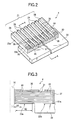
- the piezoelectric vibrator unit 4 is mainly made up of the vibrator group 21 and a fixing plate 22.
- the vibrator group 21 includes piezoelectric vibrators 28, 29 that are arrayed as a row like teeth of the comb shape. That is, the vibrator group 21 has a pair of dummy vibrators 28 and 28 located at both outermost ends in the row (in the array direction), and a plurality of drive vibrators 29... disposed between the dummy vibrators 28 and 28.
- the drive vibrators 29 are piezoelectric vibrators associated with ink droplet ejection, and formed separately one from another into needles each having an extremely narrow width of about 50 ⁇ m to 100 ⁇ m, for example.
- the dummy vibrators 28 are piezoelectric vibrator not associated with the ink droplet ejection, each having a sufficiently wider width than the drive vibrator 29 so as to provide necessary rigidity.
- Each of the piezoelectric vibrators 28, 29 in the embodiment is a piezoelectric vibrator of so-called vertical vibration mode, and expanded and contracted in a direction orthogonal to the laminating direction of the piezoelectric members 31 and the internal electrodes 32, 33 as shown in Fig. 3.
- the drive vibrator 29 is designed such that common internal electrodes 32 (corresponding to first internal electrodes of the invention) and segment internal electrodes 33 (corresponding to second internal electrodes of the invention) are laminated alternately with piezoelectric member of material (a layer of piezoelectric material) 31 interposed between the adjacent internal electrodes.
- the common internal electrodes 32 are electrodes for setting the same potential level for all drive vibrators 29.
- the segment internal electrodes 33 are electrodes, each for setting a potential level for a respective drive vibrator 29.
- the portion of the drive vibrator 29 from the leading end thereof to about a half or two thirds in the vibrator length direction (direction orthogonal to the lamination direction) is a free end part 23a.
- the remaining portion of the drive vibrator 29, namely, the portion from the end of the free end part 23a to the vibrator base end is a base end part 23b.
- the free end part 23a is formed with an active region where the common internal electrodes 32 and the segment internal electrodes 33 overlap each other (overlap portion).
- the piezoelectric material 31 in the active region is activated and deformed so that the free end part 23a is displaced (expanded or contracted) in the vibrator length direction.
- the base ends of the common internal electrodes 32 are electrically conducted to a common external electrode 37 (corresponding to a first external electrode in the invention) at the base end surface part of the drive vibrator 29.
- the leading ends of the segment internal electrodes 33 are electrically conducted to a segment external electrode 36 (corresponding to a second external electrode in the invention) at the leading end surface part of the drive vibrator 29.
- the leading ends of the common internal electrodes 32 are positioned slightly behind the leading end surface part of the drive vibrator 29 so as not to be exposed from the leading end surface part of the drive vibrator 29.
- the base ends of the segment internal electrodes 33 are positioned at the boundary between the free end part 23a and the base end part 23b.
- the segment external electrode 36 is an electrode formed on the leading end surface part of the drive vibrator 29 and a wiring connection surface (upper surface in FIG. 3) of the drive vibrator 29, i.e. one side surface in the lamination direction in the drive vibrator 29, for electrical connection of the segment internal electrodes 33 to a wiring pattern of a flexible cable 24 (corresponding to a wiring member in the invention) .
- the portion of the segment external electrode 36 on the wiring connection surface side is formed continuously from the leading end surface part to reach a position of the base end part 23b of the vibrator.
- the common external electrode 37 is an electrode formed on the base end surface part of the drive vibrator 29, and the wiring connection surface thereof for electrical connection of the common internal electrodes 32 to the wiring pattern of the flexible cable 32.
- the portion of the common external electrode 37 on the wiring connection surface is formed continuously from a position slightly behind the fixing plate (22) side end part of the segment external electrode 36 toward the base end surface part.
- piezoelectric material 31a i.e. the outermost piezoelectric material layer in the invention (hereinafter referred to as the outermost piezoelectric material layer 31a), is used as a trimming portion. That is, a portion of the outermost piezoelectric material layer 31a, which is located at the free end part 23a and which is not formed with the external electrodes 36 and 37, is used as the trimming portion the material of which is to be partially removed as a consequence of forming a partial recess (a hole, a notch, a cutout or the like) . Therefore, in the present invention, the trimming portion is a portion where a partial mass increase/decrease portion (a partial mass adjusting portion) including a partial recess and/or a partial projection is to be formed.
- a partial mass increase/decrease portion a partial mass adjusting portion
- the trimming portion is subjected to trimming such that a partial recess is formed on the leading end side of the free end part 23a of the outermost piezoelectric material layer 31a, for example, at the position distanced X1 from the leading end of the free end part 23a as shown in FIG. 3, the portion where displacement of the drive vibrator 29 is large becomes light in weight, and thus the natural vibration period becomes short.
- the trimming portion is subjected to trimming such that a partial recess is formed on the base end side of the free end part 23a of the outermost piezoelectric material layer 31a, for example, at the position distanced X2 from the leading end of the free end part 23a (at the position ahead of the base end of the free end part 23a) as illustrated in FIG. 3, the rigidity of the drive vibrator 29 is reduced, and thus the natural vibration period becomes long.
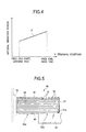
- the natural vibration period of the drive vibrator 29 becomes shorter almost linearly as the trimming position on the outermost piezoelectric material layer 31a is changed from the base end side of the free end part 23a toward the leading end side thereof, as indicated by line D in FIG. 4.
- the drive vibration period can also be finely adjusted by adjusting the depth arid range of trimming. By trimming the trimming portion, variations in the natural vibration periods of the drive vibrators 29 can be adjusted to fall within a tolerable range, and the natural vibration periods can be made uniform.
- the external electrodes 36 and 37 are not used as the trimming portion, and the outermost piezoelectric material layer 31a of the free end part 23a out of the external electrodes 36 and 37 is used as the trimming portion. Accordingly, the embodiment is free from a risk that the external electrode 36, 37 is inadvertently separated by the trimming to lose the activity of the piezoelectric material 31 facing the external electrode 36, 37.
- the limit of removal by trimming in the depth direction is set to be equal to the thickness of the outermost piezoelectric material layer 31a at most, namely, up to the range in which the segment internal electrode 33 disposed on the rear of the outermost piezoelectric material layer 31a is not damaged. This makes it impossible to impair the activity of the piezoelectric material layer 31 disposed in the rear side of the outermost piezoelectric material layer 31a.
- the outermost piezoelectric material layer 31a has the same thickness as any other piezoelectric material layer 31, but the thickness of the outermost piezoelectric material layer 31a can be set as desired. Thus, the outermost piezoelectric material layer 31a may be set to be thicker than any other piezoelectric material layer 31.
- the trimming-possible amount is increased.
- the adjustment range of the natural vibration period is widened, and damage to the segment internal electrode 33 on the rear of the outermost piezoelectric material layer 31a can be suppressed. Consequently, even if the trimming portion is too much cut due to carelessness, the sufficiently thick trimming portion can protect the segment internal electrode 33 from being damage, and the manufacturing yield can be enhanced.
- the invention is not limited to use of the outermost piezoelectric material layer 31a as the trimming portion.
- a separate member serving as a trimming portion may be provided to the outermost piezoelectric material layer 31a.
- a mass addition member 40 formed of a material higher in density than the piezoelectric material 31 is joined to the surface of each outermost piezoelectric material layer 31a to form a trimming portion. That is, the mass addition members 40 are respectively provided onto the surfaces of the outermost piezoelectric material layers 31a of the drive vibrators 29.
- the mass addition member 40 is made of a metal material, such as stainless steel or tungsten.
- the mass addition member 40 joined to the outermost piezoelectric material layer 31a is used as the trimming portion, so that the trimming portion can be trimmed for adjusting and making uniform the natural vibration periods of the drive vibrators 29...
- the outermost piezoelectric material layer 31a to which the mass addition member 40 is joined functions as an electrode damage prevention material for suppressing damage to the segment internal electrode 33 disposed on the rear of the outermost piezoelectric material layer 31a.
- the two layers i.e. the layer of the mass addition member 40 and the outermost piezoelectric material layer 31a laminated together may be used to function as the trimming portion.
- the two layers i.e. the layer of the mass addition member 40 and the outermost piezoelectric material layer 31a secure the thickness from the segment internal electrode 33 disposed on the rear of the outermost piezoelectric material layer 31a, the adjustment range can be enlarged and damage to the segment internal electrode 33 can also be suppressed.
- the mass addition member 40 is not limited to that in the first modified embodiment.
- the mass addition member 40 shorter in the vibrator length direction than that in the first modified embodiment may be provided.
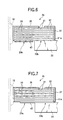
- a piezoelectric vibrator unit 4b of a second modified embodiment illustrated in FIG. 6 includes the drive vibrators 29 each having the mass addition member 40 that is joined to the surface of outermost piezoelectric material layer 31a to be slightly spaced from the fixing plate 22 and to extend to the leading end of free end part 23a,
- a piezoelectric vibrator unit 4c of a third modified embodiment illustrated in FIG. 7 includes the drive vibrators 29 each having the mass addition member 40 that is joined to the surface of outermost piezoelectric material layer 31a to extend from a position spaced at a predetermined distance from the leading end of free end part 23a to the base end of the drive vibrator 29.
- the second and third modified embodiments differs from the first modified embodiment in illustrated in FIG. 5 only with respect to the location of the mass addition member 40, and can provide the advantages similar to those of the first modified embodiment.
- the mass addition member 40 is joined to one side of the drive vibrator 29 and thus a bending mode (deflection mode) may be excited due to the rigidity of the mass addition member during the expansion and contraction of the drive vibrator 29.
- a bending mode deflection mode
- the vibration mode for expanding and contracting in the vibrator length direction is hard to be affected.
- the mass addition members 40 may be respectively joined to the opposed surfaces of the drive vibrator 29 in the lamination direction for balancing the rigidity of the drive vibrator 29.
- a piezoelectric vibrator unit 4d of a fourth modified embodiment includes the drive vibrators 29, each having the mass addition members 40 that are respectively joined to the surface of outermost piezoelectric material layer 31a and the surface of the segment external electrode 36 to correspond in location to each other and extend from a position slightly spaced at a predetermined distance from the base end of free end part 23a of drive vibrator 29 to the leading end of the free end part 23a.
- an additional mass addition member 40 the same as the mass addition member 40 in the second modified embodiment is joined to the surface of the segment external electrode 36.
- the rigidity of the drive vibrator 29 can be balanced and excitation of the bending mode can be suppressed.
- the thickness of the mass addition member 40 can be changed as desired, and may be set to match the adjustment range to be prepared for the piezoelectric vibrator unit 4.
- the base end part 23b functions as an inactive part not expanded or contracted even when the piezoelectric material 31 in the active region is activated.
- this inactive part is utilized as a wiring connection part and a fixing plate joint part.
- the flexible cable 24 is disposed on the wiring connection surface side of the base end part 23b, and the segment external electrode 36 and the common external electrode 37 are electrically connected to the flexible cable 24 on the base end part 23b. More specifically, connection end parts of the flexible cable 32 are placed on and connected to common electrode wiring parts 30 and segment electrode wiring parts 38 shown in FIG. 2.
- the flexible cable 24 is installed in place by soldering, etc.
- a drive signal is supplied through the flexible cable 24 to each electrode 32, 33, 36, 37.
- the fixing plate attachment surface of the base end part 23b functions as the fixing plate joint part onto which the fixing plate 22 is joined. In short, the drive vibrators 29... are joined onto the fixing plate 22 in a so-called cantilever state.
- the piezoelectric vibrator unit 4 as constructed above is mounted so that the leading end sides of the piezoelectric vibrators 28, 29 are directed toward the flow passage unit 3, and the leading end surface parts of the free end portions 23a of the drive vibrators 29 are contacted with and joined to the rear sides of the island parts 16 of the elastic plate 9, respectively, as shown in FIG. 1.
- the elastic membrane 14 forming the diaphragmpart 17 becomes deformed in the back and forth direction.
- the pressure chamber 12 is expanded or contracted to change the volume of the pressure chamber 12.
- a drive signal is supplied selectively to the drive vibrator 29 associated with the ink droplet ejection so that, for example, the pressure chamber 12 is once expanded, then contracted. In doing so, as the pressure chamber 12 is expanded, ink in the reservoir 14 flows into the pressure chamber 12, and as the pressure chamber 12 is contracted, the ink pressure in the pressure chamber 12 is raised. Ink pushed out from the nozzle opening 10 is ejected as an ink droplet.
- a plate-like laminate member is manufactured (laminate member manufacturing step).
- a plate-like laminate substrate is manufactured by laminating the common internal electrodes 32 and the segment internal electrodes 33 alternately with the piezoelectric material 31 interposed therebetween so that the common internal electrodes 32 and the segment internal electrodes 33 overlap in the leading end side portion forming the free end part 23a and that a non-overlapping region where only the common internal electrodes 32 exist is formed in the base end side portion forming the base end part 23b.
- a segment external electrode 31 is formed continuously on the leading end surface part of the laminate substrate and the range of the wiring connection surface from the leading end thereof to the top of the base end part 23b, and a common external electrode 37 is formed continuously on the base end surface part of the laminate substrate, and the range of the wiring connection surface from the base end thereof to the top of the base end part 23b, thereby manufacturing a laminate member with the external electrodes.
- the laminate member manufacturing step further includes a mass addition member (40) joining step. That is, after the laminate member with the external electrodes is manufactured, the mass addition member 40 is additionally joined to a surface of each outermost piezoelectric material layer 31a where the external electrodes 36 and 37 are not formed, to thereby complete the manufacture of the laminate member.
- the mass addition member (40) joining step in this example is executed after the laminate member with the external electrode is manufactured, the mass addition member (40) joining step may be executed after the laminate substrate is manufactured by laminating the internal electrodes 32 and 33 alternately with the piezoelectric material 31 interposed therebetween.
- the separate mass addition members (40) may be joined to the surface of the laminate substrate or the laminate member to correspond in location to the respective drive vibrators 29, it is preferable to join a plate or sheet forming the mass addition members 40 to the surface of the laminate substrate or the laminate member because the plate or sheet can also be divided into the mass addition members 40 by the vibrator manufacturing step described later.
- the laminate member is cut to provide a vibrator group 21 having a plurality of piezoelectric vibrators 28 and 29 arrayed in a row.
- a fixing plate 22 is joined to the fixing plate attachment surface of the base end part 23b of the laminate member by bonding or the like (a unit manufacturing step).
- a wire saw, a dicing saw, etc. is used to cut and divide the laminate member into teeth of the comb, i.e. into individual piezoelectric vibrators 28 and 29 in the form of elongated needles, as shown in FIG. 2 (a vibrator manufacturing step).
- a slant groove 39 is formed so that cutting lines for the laminate member on the fixing plate 22 side extends down to the leading end position of the fixing plate 22 and the cutting lines on the wiring connection surface side extends down to the base end surface part.
- the plate-like laminate member is joined to the fixing plate 22 before it is divided into teeth of comb is to stably divide the laminate member and facilitate handling during subsequent processing. Therefore, if the laminate member can be stably divided into teeth of comb, the laminate member may be joined to the fixing plate 22 after it is divided into teeth of comb.
- each drive vibrator 29 has an extremely narrow width of about 50 ⁇ m to 100 ⁇ m, and the mechanical processing method is adopted, the widths of the drive vibrators 29 may be varied. Further, the lengths of the free end portions 23a of the piezoelectric vibrators may be varied depending on the accuracy with which the piezoelectric vibrators are joined to the fixing plate 22. For these reasons, there is a possibility that the natural vibration periods of the drive vibrators 24 formed like comb teeth may be non-uniform from one drive vibrator 29 to another.
- the natural vibration periods of the drive vibrators 29 are made uniform according to the above-described technique (adjustment step).
- a laser beam is applied to the trimming portion of the drive vibrator 29 requiring adjustment to partially remove the trimming portion for making uniform the natural vibration periods of the drive vibrators 29.
- the natural vibration periods of the vibrators can be made the same, as a whole.
- the natural vibration period of each drive vibrator 29 is measured (S1).
- the natural vibration period of the drive vibrator 29 is measured using a laser Doppler vibration meter and an oscilloscope.
- the difference between the measured natural vibration period of the drive vibrator 29 and a target value is calculated (S2), and the trimming position and depth of the trimming portion are calculated based on the difference (S3).
- a data table indicating the relationship between the trimming positions and the natural vibration periods as shown in the graph of FIG. 4 can be provided in memory of a microcomputer forming a controller and can be used.
- a laser beam is used to trim, namely, remove a part of the trimming portion (S4), and upon completion of the adjustment for the drive vibrator 29, another drive vibrator 29 is adjusted.
- a check process of measuring the natural vibration period of the trimmed drive vibrator 29 after a part of the trimming portion is trimmed and determining whether or not the natural vibration period after the adjustment falls within the allowable range of the target value may be provided. If it is determined in the check process that the natural vibration period is not within the allowable range, again the above-described steps (51 to S4) can be repeated for enhancing the adjustment accuracy.
- Laser beam processing capable of easily executing trimming with high accuracy is used as the trimming method, but the invention is not limited to it, and any other known mechanical processing method or electric discharge processing method can also be used. Particularly, since the mass addition member 40 is trimmed in the modified embodiments described above, plasma processing less accurate than the laser beam processing can be used as the trimming method to adjust the natural vibration period without damaging the segment internal electrode 33. That is, the selection range of the trimming devices can be widened.
- the above-described manufacturing method has the advantage that each trimming portion is adjusted at the final stage of the manufacturing process of the piezoelectric vibrator unit 4, whereby the natural vibration periods of the drive vibrators 29 can be made uniform. Thus, even the piezoelectric vibrator unit 4 which had to be handled as a defective formerly can be mounted on a product by adjustment, and the manufacturing yield can also be raised.
- the ink droplet ejection characteristics of the nozzle openings 10, such as the ink droplet amount and speed can be made uniform with good accuracy, so that the image quality can be enhanced.
- the trimming portion of the drive vibrator 29 is trimmed, namely, a partial recess is formed to decrease the mass and the trimming position is adjusted, thereby adjusting the natural vibration period.
- the adjustment of the natural vibration period may be realized by adding a mass point 41 as a partial projection to the drive vibrator 29 to increase the mass and adjusting the location of the partial projection.
- the surface of a free end part 23a of a drive vibrator 29 in a lamination direction is used as a mass point addition portion to which a mass point 41 is added.
- the mass point addition portion ranges from the leading end of the free end part 23a to the base end thereof, and is formed on the surface of an outermost piezoelectric material layer 31a and the surface of a segment external electrode 36.
- the mass point addition portion may be formed on only one of the surfaces of the outermost piezoelectric material layer 31a and the segment external electrode 36.
- the mass point 41 is added to the mass point addition portion for adjusting the natural vibration period of the corresponding drive vibrator 29.
- the mass point 41 is provided by hardening a reasonably massive liquid material such as an adhesive or wax with which metal particles are mixed, or a solder, which will be hereinafter referred to as mass point material, on the surface of the free end part 23a.
- the mass point 41 has adhesion for preventing the mass point from being detached after being added.
- the piezoelectric vibrator unit 4e is manufactured as follows: First, the common internal electrodes 32 and the segment internal electrodes 33 are laminated alternately with the piezoelectric material 31 interposed therebetween so as to leave non-overlap region of only the common internal electrodes 32, thereby manufacturing a laminate substrate. Next, a segment external electrode 36 is formed continuously in the leading end surface portion of the laminate substrate and in the range of the wiring connection surface from the leading end in the wiring to a position above the base end part 23b, and a common external electrode 37 is formed continuously in the base end surface part of the laminate substrate and in the range of the wiring connection surface from the base end to a position above the base end part 23b.
- a fixing plate 22 is joined to the fix plate attachment surface of the base end part 23b in the laminate substrate, the laminate substrate is divided to have a comb shape having teeth, then an adjustment step is executed to make uniform the natural vibration periods of drive vibrators 29 in the form of teeth of comb is executed.
- a mass point material is ejected to a mass point addition portion, and the mass point material ejected on the mass point addition portion is hardened to add a mass point 41, whereby the natural vibration periods of the drive vibrators 29 are made uniform.
- the natural vibration periods of the drive vibrators 29 can be made the same, as a whole.
- the specific procedure of adjusting the natural vibration period is similar to that for trimming illustrated in FIG. 9 except that the mass point addition position of each mass point addition portion and the addition amount are calculated, based on a data table indicating the relationship between the mass point addition positions and the natural vibration periods, from the difference between the measured natural vibration period of the drive vibrator 29 and a target value, and the mass point is added by the ejection device based on the calculation values for adjusting the natural vibration period.
- the mass point 41 is added, namely, a mass is added partially to the free end part 23a, so that the natural vibration period can be adjusted so that it is prolonged. Therefore, to adjust the natural vibration period, the longest natural vibration period of the drive vibrators 29 is used as the target value to make uniform the natural vibration periods of all the drive vibrators 29.
- the piezoelectric vibrator units 4 of vertical vibration lateral effect in which each piezoelectric vibrator is expanded and contracted in the direction orthogonal to the lamination direction of the piezoelectric material 31, have been described.
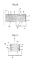
- the invention can also be applied to a piezoelectric vibrator unit 4f of vertical vibration vertical effect, in which each piezoelectric vibrator is deformed in the direction along the lamination direction of piezoelectric material 31.
- common internal electrodes 32 and segment internal electrodes 33 are laminated alternately with piezoelectric material 31 interposed between adjacent internal electrodes so that an active region is formed in each drive vibrator 29, and a common external electrode 37 electrically conducted to the common internal electrodes 32 is formed on one side of the laminate substrate, and a segment external electrode 36 electrically conducted to the segment internal electrodes 33 is formed on an opposite side of the laminate substrate.
- Each of the drive vibrators 29 has an outmost piezoelectric material layer 31a (the outermost layer of the piezoelectric material 31), the leading end of which is joined to the elastic plate 9 forming a part of the associated pressure generation chamber 12.
- a potential difference is given to the internal electrodes 32 and 33 of the drive vibrator 29 so that the drive vibrator 29 is displaced in the lamination direction (up and down direction in FIG. 11) to operate the elastic plate 9, to thereby operate the associated pressure chamber 12 for ejecting an ink droplet.
- the outmost piezoelectric material layer 31a i.e. the outermost layer in the lamination direction, is used as a trimming portion, and the trimming portion is trimmed.
- the surfaces of the segment external electrode 36 and the common external electrode 37, i.e. the surfaces of the free end part 23a, may be used as mass point addition portions to adjust the natural vibration period by adding at least one mass point 41 to one or both of the mass point addition portions.
- a mass addition material 40 may be joined to the surface of the outmost piezoelectric material layer 31a for use as a trimming portion.
- the drive vibrator 29 may be formed with a trimming portion and a mass point addition portion so as to be capable of being subjected to both trimming of the trimming portion and addition of the mass point 41 to the mass point addition portion to adjust the natural vibration period of the drive vibrator 29.
- a mass point 41 may be added to the trimming portion or the trimming of the trimming portion and the addition of a mass point 41 to the trimming portion may be executed in combination, thereby adjusting the natural vibration period of the drive vibrator 29.
- the natural vibration period of the drive vibrator can be adjusted by forming a partial mass increase/decrease portion made of a partial recess or projection.
- the adjustment for the natural vibration periods of the drive vibrators 29... are applied to the piezoelectric vibrator unit 4 per se, but the adjustment for the natural vibration periods of the drive vibrators 29... can be applied to the piezoelectric vibrator unit 4 assembled in a record head 1.
- a fourth embodiment adopting this method will be discussed.
- an adjustment opening 42 for communicating the outside of a case 2 with a storage space 5 is formed in the case 2, as indicated by the one-dotted chain line in FIG. 12.
- This adjustment opening 42 is provided for access to the drive vibrators 29... during the adjustment of the natural vibration periods of drive vibrators 29..., and enables the formation of the partial mass increase/decrease portions from the outside of the case 2.
- the adjustment opening 42 is confronted with the free end part of each of the drive vibrators 29... attached to the inside of the case 2.
- each trimming portion can be trimmed or a mass point 41 can be added to each mass point addition portion through the adjustment opening 42 to thereby form the partial mass increase/decrease portions and adjust the natural vibration periods of the drive vibrators 29... of the piezoelectric vibrator unit 4 built in the record head 1.
- the record head 1 is manufactured according to the following procedure: First, a piezoelectric vibrator unit 4 is manufactured. Briefly, common internal electrodes 32 and segment internal electrodes 33 are laminated alternately with piezoelectric material 31 interposed between adjacent internal electrodes so as to form an active region in a free end part 23a, thereby manufacturing a plate-like laminate substrate. A segment external electrode 36 and a common external electrode 37 are formed on the surface of the laminate substrate for manufacturing a laminate member with the external electrodes. If the laminate member is manufactured, a fixing plate 22 is joined to the fixing plate attachment surface of the laminate member, and the laminate member is divided into teeth of comb, i.e. a plurality of piezoelectric vibrators 28 and 29.
- the piezoelectric vibrator unit 4 is manufactured, a flow passage unit 3 and a case 2 separately manufactured are joined to each other, and the piezoelectric vibrator unit 4 is housed in the interior of the joint body, namely, in a storage space 5. If the piezoelectric vibrator unit 4 is housed in the storage space 5, the natural vibration periods of the drive vibrators 29... are adjusted. This adjustment includes a natural vibration period measuring step and a vibration period adjustment step.
- the natural vibration period measuring step is a step of measuring the natural vibration period of each drive vibrator 29 joined to an island part 16 by applying an adjustment drive signal to each drive vibrators 29...
- a laser Doppler vibration meter and an oscilloscope are used as in the above-described embodiments.
- the vibration period adjustment step is a step of making uniform the natural vibration periods of the drive vibrators 29... That is, the treatment condition for each drive vibrator 29 is set based on the measurement result at the natural vibration period measuring step, and a partial mass increase/decrease portion is formed on the surface of the free end part of the corresponding drive vibrator 29 based on the setup treatment condition. That is, a partial recess is formed by trimming and/or a partial projection is formed by adding a mass point 41 appropriately from the outside of the case 2 through the adjustment opening 42.
- the natural vibration periods of the drive vibrators 29 are adjusted in a state in which the piezoelectric vibrator unit 4 is built in the record head 1. Accordingly, it is also possible to simultaneously adjust the variations caused by factors other than the drive vibrators 29. For example, variations caused due to the factors including the joint state of each drive vibrator 29 and the island part 16 can be adjusted simultaneously. Since the natural vibration periods are adjusted at the final stage of the manufacturing process of the record head 1, there is no need to execute re-adjustment, etc., and manufacturing can be made efficient.
- the ink jet record head 1 used in an image recorder has been taken as an example of a liquid jet head, but the scope of the invention is not limited to the record head 1.
- the invention can also be applied to jet heads for industrial machines such as an optical filter manufacturing apparatus, a stamping or marking apparatus, and a microdispenser.
- the liquid jet heads, each of which uses high-durability piezoelectric vibrators, can be used stably over a long term.
- the present invention can be put into practice not only in the manners described above but also in any other manners including the following examples.
- a partial mass increase/decrease portion including a partial recess and/or projection is formed on the surface of the free end part on the outermost layer of a piezoelectric vibrator so as to adjust the natural vibration period of said piezoelectric vibrator. Accordingly, the natural vibration period of said piezoelectric vibrator can be made identical to that of any other piezoelectric vibrator. Therefore, the ejection characteristics of droplets ejected through the nozzle openings can be made uniform.
Landscapes
- Engineering & Computer Science (AREA)
- Manufacturing & Machinery (AREA)
- Physics & Mathematics (AREA)
- Optics & Photonics (AREA)
- Particle Formation And Scattering Control In Inkjet Printers (AREA)
Abstract
Description
a partial mass adjusting portion including a partial recess and/or a partial projection is provided to an outer surface of the piezoelectric vibrator in the free end part to adjust a natural vibration period of the piezoelectric vibrator.
a natural vibration period measuring step of measuring natural vibration periods of the piezoelectric vibrators one by one by applying adjusting drive signals to the piezoelectric vibrators in a state in which the leading end surface parts are joined to the elastic plate; and a vibration period adjusting step of setting a processing condition for each of the piezoelectric vibrators based on result of measurement by natural vibration period measuring step, and providing, based on the processing condition, a partial mass adjusting portion including a partial recess and/or a partial projection to an outer surface of a piezoelectric vibrator in the free end part using the adjustment opening to thereby adjust a natural vibration period of the piezoelectric vibrator.
Claims (26)
- A piezoelectric vibrator unit comprising a plurality of piezoelectric vibrators, each having at least in part, a laminate structure including first and second internal electrodes laminated alternately with a layer of piezoelectric material interposed between adjacent pairs of the first and second internal electrodes to define an active region in a free end part, a first external electrode electrically conducted to the first internal electrodes and a second external electrode electrically conducted to the second internal electrodes, wherein a potential difference is given to the piezoelectric material in the active region through the first and second external electrodes to activate the piezoelectric material, thereby displacing the free end part, wherein:
a partial mass adjusting portion including a partial recess and/or a partial projection is provided to an outer surface of the piezoelectric vibrator in the free end part. - The piezoelectric vibrator unit of claim 1, wherein.the outer surface of the piezoelectric vibrator in the free end part is used as a trimming portion where the partial recess is formed by trimming.
- The piezoelectric vibrator unit of claim 1 or 2, wherein an outermost layer of the piezoelectric material is thicker than another layer of the piezoelectric material.
- The piezoelectric vibrator unit of any one of claims 1 to 3, wherein a mass addition portion, formed of material higher in density than the piezoelectric material, is joined to a surface of an outermost layer of the piezoelectric material, and the mass addition portion is used as a trimming portion.
- The piezoelectric vibrator unit of claim 4, wherein another mass addition portion is joined to a surface of the piezoelectric vibrator opposite from the outer surface of the piezoelectric material.
- The piezoelectric vibrator unit of any one of claims 1 to 5, wherein the outer surface of the piezoelectric vibrator, other than surfaces of first and second external electrodes, is used as a trimming portion.
- The piezoelectric vibrator unit of claim 1, wherein the outer surface of the piezoelectric vibrator in the free end part is used as a mass point addition portion where the partial projection is formed by adding a mass point.
- The piezoelectric vibrator unit of claim 7, wherein the mass point is formed by applying and solidifying fluidic mass point material including an adhesive, a wax and a solder.
- The piezoelectric vibrator unit of any one of claims 1 to 8, wherein the piezoelectric vibrators are manufactured bylaminating piezoelectric material layers and internal electrode layers alternately to provide a laminate substrate; andat least partially cutting the laminate substrate to provide the piezoelectric vibrators in the form of teeth of comb.
- The piezoelectric vibrator unit of any one of claims 1 to 9, wherein each of the piezoelectric vibrator is of a piezoelectric vibrator of such a longitudinal vibration lateral effect that the free end part is displaceable in a direction perpendicular to a lamination direction.
- The piezoelectric vibrator of any one of claims 1 to 9, wherein each of the piezoelectric vibrator is of a piezoelectric vibrator of such a longitudinal vibration longitudinal effect that the free end part is displaceable in a lamination direction.
- The piezoelectric vibrator of any one of claims 1 to 11, wherein each of the piezoelectric vibrators includes an inactive part which is not displaced even when the piezoelectric material in the active region is activated, and the inactive part is joined to a fixing plate.
- A liquid jet head comprising:the piezoelectric vibrator unit of any one of claims 1 to 12; anda flow passage unit having an elastic plate forming a part of a sealing member for pressure chambers communicated with nozzle openings, wherein:
the piezoelectric vibrator unit is attached to the flow passage unit so that leading end surface parts of the piezoelectric vibrators are joined to the elastic plate. - The liquid jet head of claim 13, further comprising:a case defining a storage space in which the piezoelectric vibrator unit can be stored;an adjustment opening formed through the case for communication between an outside of the case and the storage space to enable access to the piezoelectric vibrators stored in the storage space, whereinthe partial mass adjusting portion can be provided to each of the piezoelectric vibrators from the outside of the case through the adjustment opening.
- A manufacturing method of manufacturing a piezoelectric vibrator unit comprising:a laminate member manufacturing step of laminating electrode layers forming common internal electrodes and segment internal electrodes alternately with piezoelectric material interposed between adjacent electrode layers to provide a laminate substrate defining an active region in a free end part, and subsequently forming a common external electrode and a segment external electrode on the laminate substrate to be electrically connected to the common internal electrodes and the segment internal electrodes, respectively, thereby providing a plate-like laminate member;a unit manufacturing step of joining a fixing end portion of the laminate member to a fixing plate;a vibrator manufacturing step of at least partially cutting the laminate member fixed to the fixing plate to provide comb-like piezoelectric vibrators; andan adjusting step of providing a partial recess and/or a partial projection to at least one of free end parts of outermost piezoelectric material layers, each forming an outermost layer of a corresponding piezoelectric vibrator in a lamination direction.
- The method of claim 15, wherein, in the adjusting step, the partial recess is provided by trimming the at least one of the free end parts.
- The method of claim 16, wherein, in the adjusting step, the at least one of the free end parts is trimmed by at least one of a laser beam processing, a mechanical processing, and an electric discharge processing.
- The method of claim 15, wherein, in the adjusting step, the partial projection is provided by adding a mass point onto the at least one of the free end parts.
- The method of claim 18, wherein, in the adjusting step, mass point material made of an adhesive, a wax or a solder is ejected onto the at least one of the free end parts, and solidified to provide the mass point.
- A method of manufacturing a liquid jet head comprising:a piezoelectric vibrator unit including a plurality of piezoelectric vibrators, each having at least in part, a laminate structure including first and second internal electrodes laminated alternately with a layer of piezoelectric material interposed between adjacent pairs of the first and second internal electrodes to define an active region in a free end part, a first external electrode electrically conducted to the first internal electrodes and a second external electrode electrically conducted to the second internal electrodes, wherein a potential difference is given to the piezoelectric material in the active region through the first and second external electrodes to activate the piezoelectric material, thereby displacing the free end part,a flow passage unit having an elastic plate forming a part of a sealing member for pressure chambers communicated with nozzle openings;a case defining a storage space in which the piezoelectric vibrator unit can be stored, and an adjustment opening formed through the case for communication between an outside of the case and the storage space to enable access to the piezoelectric vibrators stored in the storage space,wherein leading end surface parts of the piezoelectric vibrators are joined to the elastic plate, and the liquid jet head is adapted so that deformation of a piezoelectric vibrator causes deformation of a pressure chamber and varies pressure of liquid in the pressure chamber to thereby eject liquid from an associated nozzle opening,said method comprising:a natural vibration period measuring step of measuring natural vibration periods of the piezoelectric vibrators one by one by applying adjusting drive signals to the piezoelectric vibrators in a state in which the leading end surface parts are joined to the elastic plate; anda vibration period adjusting step of setting a processing condition for each of the piezoelectric vibrators based on result of measurement by natural vibration period measuring step, and providing, based on the processing condition, a partial mass adjusting portion including a partial recess and/or a partial projection to an outer surface of a piezoelectric vibrator in the free end part using the adjustment opening to thereby adjust a natural vibration period of the piezoelectric vibrator.
- A piezoelectric vibrator unit comprising a plurality of drive vibrators, each having at least in part, a laminate structure including first and second internal electrodes laminated alternately with a layer of piezoelectric material interposed between adjacent pairs of the first and second internal electrodes to form an active region, a first external electrode electrically conducted to the first internal electrodes and a second external electrode electrically conducted to the second internal electrodes, wherein:
at least one of the drive vibrators has a recess and/or projection that is located in the active region and provided to an outer surface of the drive vibrator. - The piezoelectric vibrator unit of claim 21, wherein the outer surface where the recess and/or projection is located is defined by an outermost piezoelectric material layer.
- The piezoelectric vibrator unit of claim 21, wherein the outer surface where the recess and/or projection is located is defined by a member attached to an outermost piezoelectric material layer and made of material different from the piezoelectric material.
- The piezoelectric vibrator unit of claim 21, wherein the outer surface where the projection is located is defined by one of first and second external electrodes.
- The piezoelectric vibrator unit of claim 21, wherein the outer surface where the recess and/or projection is located extends in a direction parallel to a direction in which the first and second internal electrodes are laminated.
- The piezoelectric vibrator unit of claim 21, wherein the outer surface where the recess and/or projection is located extends in a direction perpendicular to a direction in which the first and second internal electrodes are laminated.
Applications Claiming Priority (2)
| Application Number | Priority Date | Filing Date | Title |
|---|---|---|---|
| JP2000030525 | 2000-02-08 | ||
| JP2000030525 | 2000-02-08 |
Publications (2)
| Publication Number | Publication Date |
|---|---|
| EP1124266A2 true EP1124266A2 (en) | 2001-08-16 |
| EP1124266A3 EP1124266A3 (en) | 2005-04-06 |
Family
ID=18555524
Family Applications (1)
| Application Number | Title | Priority Date | Filing Date |
|---|---|---|---|
| EP01102774A Withdrawn EP1124266A3 (en) | 2000-02-08 | 2001-02-08 | Piezoelectric vibrator unit, liquid jet head, manufacturing method of piezoelectric vibrator unit, and manufacturing method of liquid jet head |
Country Status (2)
| Country | Link |
|---|---|
| US (1) | US6398350B2 (en) |
| EP (1) | EP1124266A3 (en) |
Families Citing this family (16)
| Publication number | Priority date | Publication date | Assignee | Title |
|---|---|---|---|---|
| US6631986B2 (en) * | 1998-12-16 | 2003-10-14 | Silverbrook Research Pty Ltd | Printer transport roller with internal drive motor |
| US6732414B2 (en) * | 1999-12-27 | 2004-05-11 | Seiko Epson Corporation | Method of manufacturing a liquid ink jet head |
| US20010026114A1 (en) * | 2000-03-29 | 2001-10-04 | Tokin Ceramics Corporation | Multilayer piezoelectric actuator with electrodes reinforced in conductivity |
| JP2003037306A (en) * | 2001-07-25 | 2003-02-07 | Murata Mfg Co Ltd | Laminated piezoelectric element and piezoelectric actuator using the same |
| US6953241B2 (en) | 2001-11-30 | 2005-10-11 | Brother Kogyo Kabushiki Kaisha | Ink-jet head having passage unit and actuator units attached to the passage unit, and ink-jet printer having the ink-jet head |
| DE10317872A1 (en) * | 2002-04-18 | 2004-01-08 | Hitachi Printing Solutions, Ltd., Ebina | Ink jet head and process for its manufacture |
| JP4145760B2 (en) * | 2002-10-03 | 2008-09-03 | セイコーエプソン株式会社 | Piezoelectric actuator unit and manufacturing method thereof |
| JP4235804B2 (en) * | 2003-03-04 | 2009-03-11 | セイコーエプソン株式会社 | Piezoelectric element forming member, piezoelectric element forming unit, piezoelectric element unit, and liquid jet head |
| JP4251190B2 (en) * | 2006-04-10 | 2009-04-08 | セイコーエプソン株式会社 | Liquid ejecting head and liquid ejecting apparatus |
| US8246149B2 (en) * | 2006-04-10 | 2012-08-21 | Seiko Epson Corporation | Liquid ejecting head and liquid ejecting apparatus |
| US8702997B2 (en) | 2011-06-02 | 2014-04-22 | Hewlett-Packard Development Company, L.P. | Balancing a microelectromechanical system |
| JP2013051236A (en) * | 2011-08-30 | 2013-03-14 | Seiko Epson Corp | Piezoelectric element unit, liquid ejecting head, and liquid ejecting apparatus |
| JP2014034114A (en) * | 2012-08-07 | 2014-02-24 | Seiko Epson Corp | Liquid jetting head and liquid jetting device |
| JP6282111B2 (en) * | 2013-03-26 | 2018-02-21 | 株式会社村田製作所 | Ceramic electronic components |
| JP5679010B2 (en) * | 2013-05-07 | 2015-03-04 | Tdk株式会社 | Piezoelectric element and manufacturing method thereof |
| JP6874463B2 (en) * | 2017-03-27 | 2021-05-19 | セイコーエプソン株式会社 | Piezoelectric elements, piezoelectric actuators, ultrasonic probes, ultrasonic devices, electronic devices, liquid injection heads, and liquid injection devices |
Family Cites Families (7)
| Publication number | Priority date | Publication date | Assignee | Title |
|---|---|---|---|---|
| JP3041952B2 (en) * | 1990-02-23 | 2000-05-15 | セイコーエプソン株式会社 | Ink jet recording head, piezoelectric vibrator, and method of manufacturing these |
| JP3355738B2 (en) * | 1993-12-22 | 2002-12-09 | セイコーエプソン株式会社 | Inkjet head |
| JP3422349B2 (en) * | 1995-02-23 | 2003-06-30 | セイコーエプソン株式会社 | Ink jet recording head |
| JPH1095112A (en) * | 1996-09-25 | 1998-04-14 | Seiko Epson Corp | Actuator for inkjet printer |
| JP3378775B2 (en) * | 1997-07-07 | 2003-02-17 | 株式会社村田製作所 | Piezoelectric resonator and frequency adjustment method thereof |
| JPH11168338A (en) * | 1997-10-01 | 1999-06-22 | Murata Mfg Co Ltd | Piezoelectric resonator, frequency adjustment method for piezoelectric resonator and communication equipment |
| JP3381779B2 (en) * | 1998-09-17 | 2003-03-04 | セイコーエプソン株式会社 | Piezoelectric vibrator unit, method of manufacturing piezoelectric vibrator unit, and ink jet recording head |
-
2001
- 2001-02-08 US US09/778,767 patent/US6398350B2/en not_active Expired - Fee Related
- 2001-02-08 EP EP01102774A patent/EP1124266A3/en not_active Withdrawn
Also Published As
| Publication number | Publication date |
|---|---|
| EP1124266A3 (en) | 2005-04-06 |
| US6398350B2 (en) | 2002-06-04 |
| US20010017503A1 (en) | 2001-08-30 |
Similar Documents
| Publication | Publication Date | Title |
|---|---|---|
| US6398350B2 (en) | Piezoelectric vibrator unit, liquid jet head, manufacturing method of piezoelectric vibrator unit, and manufacturing method of liquid jet head | |
| US6732414B2 (en) | Method of manufacturing a liquid ink jet head | |
| JP3454250B2 (en) | Method of manufacturing piezoelectric vibrator unit and liquid jet head | |
| US5630274A (en) | Method of making an ink jet recording head | |
| JP2004001338A (en) | Liquid jet head and method of manufacturing the same | |
| US6286942B1 (en) | Ink jet recording head with mechanism for positioning head components | |
| JP2005034997A (en) | Liquid jet head | |
| US9090057B2 (en) | Piezoelectric unit, liquid ejecting head, and liquid ejecting apparatus | |
| JP3738895B2 (en) | Piezoelectric vibrator unit, liquid jet head, and method of manufacturing piezoelectric vibrator unit | |
| JP3185812B2 (en) | Inkjet head | |
| JP3491193B2 (en) | Ink jet recording head and ink jet recording apparatus | |
| JP2003231254A (en) | Ink jet recording head and ink jet recording apparatus | |
| JP3114766B2 (en) | Ink jet head and method of manufacturing the same | |
| JP3520436B2 (en) | Ink jet recording head unit and ink jet recording head | |
| JPH06238895A (en) | Ink jet head and manufacture thereof | |
| JP3473034B2 (en) | Inkjet recording head | |
| JP2003237077A (en) | Ink jet recording head and ink jet recording apparatus | |
| JP3362787B2 (en) | Piezoelectric unit for inkjet recording head | |
| JP3991767B2 (en) | Method for determining appropriate voltage of ink jet recording head | |
| JP2011101982A (en) | Method of manufacturing liquid ejection head | |
| JP4158149B2 (en) | Ink jet head, ink jet recording apparatus, and housing forming method | |
| JP2000094683A (en) | Head device for inkjet printer | |
| JPH04185446A (en) | inkjet printer head | |
| JP2004230680A (en) | Liquid ejecting head and liquid ejecting apparatus | |
| JP2004291362A (en) | Inkjet recording head and recorder equipped with the same |
Legal Events
| Date | Code | Title | Description |
|---|---|---|---|
| PUAI | Public reference made under article 153(3) epc to a published international application that has entered the european phase |
Free format text: ORIGINAL CODE: 0009012 |
|
| AK | Designated contracting states |
Kind code of ref document: A2 Designated state(s): AT BE CH CY DE DK ES FI FR GB GR IE IT LI LU MC NL PT SE TR |
|
| AX | Request for extension of the european patent |
Free format text: AL;LT;LV;MK;RO;SI |
|
| PUAL | Search report despatched |
Free format text: ORIGINAL CODE: 0009013 |
|
| AK | Designated contracting states |
Kind code of ref document: A3 Designated state(s): AT BE CH CY DE DK ES FI FR GB GR IE IT LI LU MC NL PT SE TR |
|
| AX | Request for extension of the european patent |
Extension state: AL LT LV MK RO SI |
|
| 17P | Request for examination filed |
Effective date: 20050727 |
|
| AKX | Designation fees paid |
Designated state(s): AT BE CH CY DE DK ES FI FR GB GR IE IT LI LU MC NL PT SE TR |
|
| 17Q | First examination report despatched |
Effective date: 20050825 |
|
| STAA | Information on the status of an ep patent application or granted ep patent |
Free format text: STATUS: THE APPLICATION IS DEEMED TO BE WITHDRAWN |
|
| 18D | Application deemed to be withdrawn |
Effective date: 20061115 |