BACKGROUND OF THE INVENTION
1. Field of the Invention
The present invention relates to an optical
pickup for exposing a laser beam passed through a
diffraction grating to an optical disk, a tilt detection
apparatus, a tilt detection method for detecting a tilt
of the optical disk, and an optical disk apparatus.
2. Description of the Related Art
In the optical disk apparatus, when a tilt exists
on the optical disk, the deterioration of the signal
quality of a recording signal and/or a reproducing signal
of the optical disk may be occurred. For correcting the
tilt of the optical disk, it is necessary to detect the
tilt of the optical disk and generate a signal in
response to the tilt.
An invention of an optical pickup is disclosed in
Japanese Unexamined Patent Publication (Kokai) No.9-128785.
In this Publication, in an optical pickup
comprising a laser beam source, an objective lens and an
aberration correction use liquid crystal panel, it is
disclosed to change the refractive index of the liquid
crystal panel in response to the thickness or the tilting
angle of the liquid crystal panel.
Further, it is disclosed that a tilt sensor
detects the tilting angle and a liquid crystal panel
control circuit drives the liquid crystal panel to change
the refractive index based on the tilting angle.
In the optical pickup of said Publication No.9-128785,
the position for arranging the tilt sensor is
restricted, and, in the optical disk, a point to which
the laser beam is exposed is different from a point where
the tilt sensor detects the tilt, and thus it is
difficult to detect the tilt of the optical disk
precisely.
SUMMARY OF THE INVENTION
An object of the present invention is to provide a
tilt detection apparatus and a tilt detection method
capable of detecting a tilt of an optical disk.
Further, another object of the present invention is
to provide an optical pickup applicable in said tilt
detection apparatus.
Further, still another object of the present
invention is to provide an optical disk apparatus.
A first optical pickup according to the present
invention comprises a laser for outputting a laser beam;
a diffraction grating for diffracting the laser beam from
said laser to generate a 0th order diffraction beam and
+-first order diffraction beams; an objective lens for
collecting said 0th order diffraction beam and said +-first
order diffraction beams and exposing the beams to
an optical disk on which track guide grooves are formed;
and a photodetector for generating signals in response to
said +-first order diffraction beams reflected at said
optical disk, and each of said +-first order diffraction
beams exposed to said optical disk has the phase
distribution equal to or substantially equal to the phase
distribution due to the wave front aberration generated
on said optical disk when said optical disk is tilted,
and said photodetector comprises light receiving portions
for receiving each of said +-first order diffraction
beams reflected at said optical disk, and each of said
light receiving portions is divided in the direction in
response to the track direction on said optical disk.
In the first optical pickup according to the present
invention, preferably, said objective lens collects said
0th order diffraction beam and exposes it to the track of
said optical disk, and a distance from the center part
of the optical spot of said Oth order diffraction beam to
the center part of the optical spots of said +-first
order diffraction beams in the disk radial direction is,
where n is an integer of 0 or more, equal to or
approximately equal to a (n/2 + 1/4) times of the pitch
of said track or said track guide groove.
In the first optical pickup according to the present
invention, preferably, said phase distribution of one of
said +-first order diffraction beams is a phase
distribution generated when the tilting angle of said
optical disk is a positive constant angle, and said phase
distribution of another of said +-first order diffraction
beams is a phase distribution generated when the tilting
angle of said optical disk is a negative constant angle.
In the first optical pickup according to the present
invention, preferably, it further comprises an actuator
for moving said objective lens in the disk radial
direction in response to an eccentricity of said optical
disk, and a position sensor for detecting the quantity of
movement or the quantity of change of said objective
lens.
A second optical pickup according to the present
invention comprises a laser for outputting a laser beam,
a first diffraction grating for diffracting the laser
beam from said laser to generate a main laser beam
including a 0th order diffraction beam and first and
second sub laser beams including one of +-first order
diffraction beams, a second diffraction grating for
diffracting said main laser beam to generate a main laser
diffraction beam including a 0th order diffraction beam
and third and forth sub laser diffraction beams including
one of +-first order diffraction beams and diffracting
said first and second sub laser beams to generate first
and second sub laser diffraction beams including a 0th
order diffraction beam, an objective lens for collecting
said main laser diffraction beams and said first to forth
sub laser diffraction beams and exposing the beams to an
optical disk on which track guide grooves are formed, and
a photodetector for generating signals in response to
said main laser diffraction beams and said first to forth
sub laser diffraction beams reflected at said optical
disk, and each of said first and second sub laser
diffraction beams exposed to said optical disk has the
phase distribution equal to or substantially equal to the
phase distribution due to the wave front aberration
generated on said optical disk when said optical disk is
tilted.
In the second optical pickup according to the present
invention, preferably, said objective lens collects said
main laser diffraction beam and exposes it to the track
of said optical disk, and a distance from the center part
of the optical spot of said main laser diffraction beam
to the center part of the optical spots of said first and
second sub laser diffraction beams in the disk radial
direction is, where n is an integer of 0 or more, equal
to or approximately equal to a (n/2 + 1/4) times of the
pitch of said track or said track guide groove.
In the second optical pickup according to the present
invention, preferably, a distance from the center part of
the optical spot of said main laser diffraction beam to
the center part of the optical spots of said third and
forth sub laser diffraction beams in the disk radial
direction is, when m is an integer of 0 or more, equal to
or approximately equal to a (m + 1 / 2) times of the
pitch of said track or said track guide groove.
In the second optical pickup according to the present
invention, preferably, said phase distribution of one of
said first or second sub laser diffraction beams is a
phase distribution generated when the tilting angle of
said optical disk is a positive constant angle, and said
phase distribution of another of said first or second sub
laser diffraction beams is a phase distribution generated
when the tilting angle of said optical disk is a negative
constant angle.
In the second optical pickup according to the present
invention, preferably, said photodetector comprises light
receiving portions for receiving each of said main laser
diffraction beam and said first to forth sub laser
diffraction beams reflected at said optical disk, and
each of said light receiving portions is divided in the
direction in response to the track direction on said
optical disk
In the second optical pickup according to the present
invention, for example, it may be made the configuration
which said wave front aberration is the coma aberration
generated at a transparency substrate of said optical
disk.
A first tilt detection apparatus according to the
present invention comprises a laser for outputting a
laser beam, a diffraction grating for diffract the laser
beam from said laser to generate a 0th order diffraction
beam and +-first order diffraction beams, an objective
lens for collecting said 0th order diffraction beam and
+-first order diffraction beams and exposing the beams to
the optical disk on which track guide grooves are formed,
a generating circuit for generating push-pull signals of
said +-first order diffraction beams reflected at said
optical disk, and a detection circuit for detecting a
tilt of said optical disk based on the sum of the push-pull
signals of said +-first order diffraction beams, and
each of said +-first order diffraction beams exposed to
said optical disk has the phase distribution equal to or
substantially equal to the phase distribution due to the
wave front aberration generated on said optical disk when
said optical disk is tilted.
In the first tilt detection apparatus according to
the present invention, preferably, said objective lens
collects said 0th order diffraction beam and exposes it
to the track of said optical disk, and a distance from
the center part of the optical spot of said 0th order
diffraction beam to the center part of the optical spots
of said +-first order diffraction beams in the disk
radial direction is, where n is an integer of 0 or more,
equal to or approximately equal to a (n/2 + 1/4) times of
the pitch of said track or said track guide groove.
In the first tilt detection apparatus according to
the present invention, preferably, said phase
distribution of one of said +-first order diffraction
beams is a phase distribution generated when the tilting
angle of said optical disk is a positive constant angle,
and said phase distribution of another of said +-first
order diffraction beams is a phase distribution generated
when the tilting angle of said optical disk is a negative
constant angle.
In the first tilt detection apparatus according to
the present invention, preferably, it further comprises a
photodetector, said photodetector comprises light
receiving portions for receiving each of said +-first
order diffraction beams reflected at said optical disk,
and each of said light receiving portions is divided in
the direction in response to the track direction on said
optical disk, and said generating circuit generates the
push-pull signals of said +-first order diffraction beams
based on the output signals from said light receiving
portions of said photodetector.
In the first tilt detection apparatus according to
the present invention, preferably, it further comprises
an actuator for moving said objective lens in the disk
radial direction in response to an eccentricity of said
optical disk, and a position sensor for detecting the
quantity of movement or the quantity of change of said
objective lens, and said detection circuit generates an
eccentricity signal in response to the eccentricity of
said optical disk based on said quantity of movement or
the quantity of change detected by said position sensor
and detecting a tilt of said optical disk based on the
deference between the sum of the push-pull signals of
said +-first order diffraction beams and said
eccentricity signal.
A second tilt detection apparatus according to the
present invention comprises a laser for outputting a
laser beam, a first diffraction grating for diffracting
the laser beam from said laser to generate a main laser
beam including a 0th order diffraction beam and first and
second sub laser beams including one of +-first order
diffraction beams, a second diffraction grating for
diffracting said main laser beam to generate a main laser
diffraction beam including a 0th order diffraction beam
and third and forth sub laser diffraction beams including
one of +-first order diffraction beams and diffracting
said first and second sub laser beams to generate first
and second sub laser diffraction beams including a 0th
order diffraction beam, an objective lens for collecting
said main laser diffraction beam and said first to forth
sub laser diffraction beams and exposing the beams to an
optical disk on which track guide grooves are formed, a
generating circuit for generating push-pull signals of
said main laser diffraction beam and said first to forth
sub laser diffraction beams reflected at said optical
disk, and a detection circuit for generating an
eccentricity signal in response to the eccentricity of
said optical disk based on the push-pull signals of said
main laser diffraction beam and said third and forth sub
laser diffraction beams and detecting a tilt of said
optical disk based on the deference between the sum of
the push-pull signals of said first and second sub laser
diffraction beams and said eccentricity signal, and each
of said first and second sub laser diffraction beams
exposed to said optical disk has the phase distribution
equal to or substantially equal to the phase distribution
due to the wave front aberration generated on said
optical disk when said optical disk is tilted.
In the second tilt detection apparatus according to
the present invention, preferably, said objective lens
collects said main laser diffraction beam and exposes it
to the track of said optical disk, and a distance from
the center part of the optical spot of said main laser
diffraction beam to the center part of the optical spots
of said first and second sub laser diffraction beams in
the disk radial direction is, where n is an integer of 0
or more, equal to or approximately equal to a (n/2 + 1/4)
times of the pitch of said track or said track guide
groove.
In the second tilt detection apparatus according to
the present invention, further preferably, a distance
from the center part of the optical spot of said main
laser diffraction beam to the center part of the optical
spots of said third and forth sub laser diffraction beams
in the disk radial direction is, when m is an integer of
0 or more, equal to or approximately equal to a (m + ½)
times of the pitch of said track or said track guide
groove.
In the second tilt detection apparatus according to
the present invention, preferably, said phase
distribution of one of said first or second sub laser
diffraction beams is a phase distribution generated when
the tilting angle of said optical disk is a positive
constant angle, and said phase distribution of another of
said first or second sub laser diffraction beams is a
phase distribution generated when the tilting angle of
said optical disk is a negative constant angle.
In the second tilt detection apparatus according to
the present invention, preferably, it further comprises a
photodetector, and said photodetector comprises light
receiving portions for receiving each of said main laser
diffraction beams and said first to forth sub laser
diffraction beams reflected at said optical disk, and
each of said light receiving portions is divided in the
direction in response to the track direction on said
optical disk, and said generating circuit generates the
push-pull signals of said main laser diffraction beam and
said first to forth sub laser diffraction beams based on
the output signals from said light receiving portions of
said photodetector.
A first tilt detection method according to the
present invention comprises the steps of diffracting a
laser beam to generate a 0th order diffraction beam and
+-first order diffraction beams and exposing said
generated 0th order diffraction beam and +-first order
diffraction beams to an optical disk on which the track
guide grooves are formed, generating push-pull signals of
said +-first order diffraction beams reflected at said
optical disk, and detecting the tilt of said optical disk
based on the sum of the push-pull signals of said +-first
order diffraction beams, and each of said +-first order
diffraction beams reflected at said optical disk has the
phase distribution equal to or substantially equal to the
phase distribution due to the wave front aberration
generated on said optical disk when said optical disk is
tilted.
In the first tilt detection method according to the
present invention, preferably, said exposing step has the
steps of collecting said 0th order diffraction beam and
+-first order diffraction beams and exposing said 0th
order diffraction beam to the track of said optical disk,
and a distance from the center part of the optical spot
of said 0th order diffraction beam to the center part of
the optical spots of said +-first order diffraction beams
in the disk radial direction is, where n is an integer of
0 or more, equal to or approximately equal to a (n/2 +
1/4) times of the pitch of said track or said track guide
groove.
In the first tilt detection method according to the
present invention, preferably, said phase distribution of
one of said +-first order diffraction beams is a phase
distribution generated when the tilting angle of said
optical disk is a positive constant angle, and said phase
distribution of another of said +-first order diffraction
beams is a phase distribution generated when the tilting
angle of said optical disk is a negative constant angle,
In the first tilt detection method according to the
present invention, preferably, ut further comprises the
step of generating an eccentricity signal in response to
the eccentricity of said optical disk, and said detecting
step has a step of detecting the tilt of said optical
disk based on the difference between the sum of the push-pull
signals of said +-first order diffraction beams and
said eccentricity signal.
A second tilt detection method according to the
present invention comprises the steps of diffracting the
laser beam to generate a main laser beam including a 0th
order diffraction beam and first and second sub laser
beams including one of +-first order diffraction beams,
diffracting said main laser beam to generate a main laser
diffraction beam including a 0th order diffraction beam
and third and forth sub laser diffraction beams including
one of +-first order diffraction beams and diffracting
said first and second sub laser beams to generate first
and second sub laser diffraction beams including a 0th
order diffraction beam, exposing said main laser
diffraction beam and said first to forth sub laser
diffraction beams to an optical disk on which track guide
grooves are formed, generating push-pull signals of said
main laser diffraction beam and said first to forth sub
laser diffraction beams reflected at said optical disk,
and generating an eccentricity signal in response to the
eccentricity of said optical disk based on the push-pull
signals of said main laser diffraction beam and said
third and forth sub laser diffraction beams and detecting
a tilt of said optical disk based on the deference
between the sum of the push-pull signals of said first
and second sub laser diffraction beams and said center
eccentricity signal, and each of said first and second
sub laser diffraction beams exposed to said optical disk
has the phase distribution equal to or substantially
equal to the phase distribution due to the wave front
aberration generated on said optical disk when said
optical disk is tilted.
In the second tilt detection method according to the
present invention, preferably, said exposing step has a
step of collecting said main laser diffraction beam and
said first to forth sub laser diffraction beams and
exposing said main laser diffraction beam to the track of
said optical disk, and a distance from the center part of
the optical spot of said main laser diffraction beam to
the center part of the optical spots of said first and
second sub laser diffraction beams in the disk radial
direction is, where n is an integer of 0 or more, equal
to or approximately equal to a (n/2 + 1/4) times of the
pitch of said track or said track guide groove.
In the second tilt detection method according to the
present invention, further preferably, a distance from
the center part of the optical spot of said main laser
diffraction beam to the center part of the optical spots
of said third and forth sub laser diffraction beams in
the disk radial direction is, when m is an integer of 0
or more, equal to or approximately equal to a (m + 1 / 2)
times of the pitch of said track or said track guide
groove.
In the second tilt detection method according to the
present invention, preferably, said phase distribution of
one of said first or second sub laser diffraction beams
is a phase distribution generated when the tilting angle
of said optical disk is a positive constant angle, and
said phase distribution of another of said first or
second sub laser diffraction beams is a phase
distribution generated when the tilting angle of said
optical disk is a negative constant angle.
An optical disk apparatus according to the present
invention comprises an optical pickup for diffracting a
laser beam from a laser, generating a 0 order diffraction
beam and +-first order diffraction beams having the phase
distribution equal to or approximately equal to the phase
distribution due to the wave front aberration of an
optical disk when the optical disk is tilted, exposing
the 0 order diffraction beam and +-first order
diffraction beams to the optical disk, and receiving
reflected beams of said exposed beams from the optical
disk to generate signals in response to each of the
reflected signals, a signal generation circuit for
generating push-pull signals of said received reflected
beams of at least said +-first order diffraction beams, a
tilt detection circuit for detecting the tilt of the
optical disk based on the sum of said generated push-pull
signals of said +-first order diffraction beams, and a
tilt correction portion for correcting the tilt of the
optical disk in response to said detected tilt.
In the first tilt detection apparatus according to
the present invention mentioned above, the +-primary
diffraction beams generated by the diffraction grating
have a phase distribution equal to or nearly equal to the
phase distribution due to the wave front aberration
generated on the optical disk while the optical disk has
a tilt.
By said phase distribution, the push-pull signal of
one of the +-primary diffraction beams becomes the
maximum value at the certain tilt angle() and the push-pull
signal of another of the +-primary diffraction beams
becomes the minimum value at the certain tilt angle(-).
By obtaining an additional signal as the result of
addition of the push-pull signals of the +-primary
diffraction beams, the value of the additional signal can
be made 0 while the tilt angle of the optical disk is 0°
and the symmetrical additional signal corresponding to
the positive and negative tilt angles can be obtained, so
that the tilt angle is detectable by the additional
signal.
In the second tilt detection apparatus according to
the present invention mentioned above, the first and
second sub laser diffraction beams generated by the first
and second diffraction gratings have a phase distribution
equal to or substantially equal to the phase distribution
due to the wave front aberration generated on the optical
disk while the optical disk has a tilt,
By said phase distribution, the push-pull signal of
one of the first and second sub laser diffraction beams
becomes the maximum value at the certain tilt angle (8)
and the push-pull signal of another of the first and
second sub laser diffraction beams becomes the minimum
value at the certain tilt angle(-) . By obtaining an
additional signal as the result of addition of the push-pull
signals of the first and second additional beams,
the value of the additional signal can be made 0 while
the tilt angle of the optical disk is 0° and the
symmetrical additional signal corresponding to the
positive and negative tilt angles can be obtained, so
that the tilt angle is detectable by the additional
signal.
BRIEF DESCRIPTION OF THE DRAWINGS
These and other objects and features of the present
invention will become more clearer from the following
description of the preferred embodiments with reference
to the accompanying drawings, in which:
DESCRIPTION OF THE PREFERRED EMBODIMENTS
Preferred embodiments of the present invention will
be explained with reference to the attached drawings.
An optical disk apparatus generally comprises an
optical pickup, collects a laser beam outputted from the
semiconductor laser inside the optical pickup, and
exposes it to the optical disk.
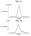
Fig. 1A and 1B are views for explaining the
relationship between the light intensity and the position
of the light spots formed on the optical disk as an
example- Fig. 1A is a view for showing the relationship
between the light intensity and the position when the
optical disk is not tilted (on track state) as an
example. Fig. 1B is a view for explaining the
relationship between the light intensity and the position
when the optical disk is tilted as an example.
When the optical disk is tilted (inclined), the
intensity of the center of the light spots becomes lower
and the siderobe appears in the tilting direction.
Further, due to the lowering or the intensity of the
center of the light spot, the amplitude of the
reproducing signal in response to the quantity of the
reflected light is decreased, and thus the quality of the
signal may deteriorates.
This is because, when the laser beam strikes a
transparency substrate (disk substrate) of the tilted
optical disk, the laser beam passed through the
transparency substrate to the recording plane is
effected, the spatial phase distribution, for example the
phase distribution due to the wave front aberration, and
the collecting performance of the light spot formed on
the recording surface becomes lower.
When the phase distribution corresponding to the
tilting angle is given to one laser beam in advance,
the phase distribution corresponding to the tilting angle
- is given to another laser beam in advance, and both
the laser beams having equal light intensities, the
reproduced push-pull signals obtained from each of the
laser beams are shown by the characteristic curves A and
B in Fig. 2. Then, by adding the both reproducing push-pull
signals to generate the sum signal, the
characteristic curve becomes (A+B), so that the tilt
error signal in response to the tilts (or the tilting
angle) of positive and negative can be obtained.
In the present embodiment, to detect a tilt of an
optical disk, the phase distribution equal to or
approximately equal to the phase distribution generated
due to the tilt of the disk substrate in the disk radial
direction is added to the laser beam by using the
diffraction grating before the striking it to the optical
disk.
In the optical pickup of the related art, the 0th
order diffraction beam and the +-first order diffraction
beams, generated by the laser beam passed through the
diffraction grating, have a homogeneous or substantially
homogeneous phase distribution in a propagation
direction. The 0th order diffraction beam and the +-first
order diffraction beams pass through the objective lens
to form one main light spot and two sub light spots on
the optical disk at the same time.
On the other hand, by forming the diffraction grating
the specific pattern, the 0th order diffraction beam may
have the homogeneous phase and the +-first order
diffraction beams may be given the spatial phase
distributions generated when they pass through the disk
substrate tilting in positive direction and negative
direction.
As the result, passing through the objective lens,
one main light spot when the optical disk is not tilted
and
two sub light spots equal to or substantially equal to
the case the positive and negative tilts exist, may be
formed on the optical disk at the same time.
Here, by applying the computer hologram technology,
the interference fringes formed on a screen by the laser
beam striking the screen in a right angle and having a
homogeneous phase distribution and laser beams striking
the screen with the predetermined angle and direction to
the above laser beam having the homogeneous phase
distribution and having spatial phase distributions
generated when they pass through the disk substrate
tilting in positive direction or negative direction, can
be obtained found by a computer.
Note that, the angle and direction of the two laser
beams are matched to the angle and direction of the 0th
order diffraction beam and the +-first order diffraction
beams after passing through the diffraction grating in
the case that the diffraction grating is mounted on the
optical pickup.
First, the phase distribution of the laser beam
passing through the tilted disk substrate is defined by
the equations. The description by polynomial development
of the wave front aberration is used for defining the
equations.
By the polynomial development of the wave front
aberration, the coma aberration is major part of the wave
front aberration generated by the tilting transparency
substrate.
When this coma aberration Wc is expressed by the
following equation (1), where x is a position in the disk
radial direction, and an orthogonal coordinate (x,y)
standardized (normalized) by the aperture radius on the
aperture plane of the objective lens.
Wc(x,y)= 2πW11x + 2πW31x (x2+y2) + 2πW51x (x2+y2)2
In the above equation (1), W11 is a wave front
coefficient for determining the position of the light
spot formed on the optical disk, and since it doesn't
influence the shape of the light spot, any value can be
chosen.
Further, W31 and W51 are coma aberration coefficients
W31(λ) and W51(λ) standardized (normalized) by the laser
beam wavelength λ, and each of them is shown in the
following equations (2) and (3).
W31 (λ) = { (n2-1) n2tNA3sincos} / {2λ (n2-sin2) 9/2}
W51 (λ) = { (n2-1) n2tNA5 (n4+3n2cos2-5n2sin2+4sin2-sin4) sincos} / {8λ (n2-sin2) 9/2 }
In the above equations (2) and (3), NA is a numerical
aperture of the objective lens, λ is a wavelength of the
laser beam from the light source, n is the reflective
index of the disk substrate, t is the thickness of the
disk substrate, and is the tilting angle indicating the
tilt of the disk substrate. The material of the disk
substrate is, for example, the polycarbonate and its
reflective index is about 1.5.
To the laser beam having the homogeneous phase
distribution, the phase distribution Wd of the laser beam
striking with the tilt of direction β and the angle a to
the laser beam having the homogeneous phase distribution
is expressed by the equation (4), where x is a position
in the disk radial direction and the orthogonal
coordinate (x,y) standardized (normalized) by the
aperture radius r on the aperture plane of the objective
lens. Note, the tilt direction β is 0 degree in a radial
direction (or x direction) and 90 degree in a track
direction.
Wd(x,y)={2πr(xcosβ+ysinβ)sinα}/λ
Under the above conditions, the interference fringes
appeared by the laser beam having the phase distribution
of {Wc(x, y)+Wd(x, y) } when λ is a certain value and the
laser beam with the homogeneous phase striking the screen
vertically, is calculated.
Fig. 3 is a view for explaining the interference
fringes calculated under the conditions of =1.0°,
α=0.2°, and β=90°. Note that, NA=0.6, λ 650nm, t=0.6mm,
n=1.5, r=2mm, and W11=-2W31/3-W51/2 are set. Further, a
ring in Fig. 3 corresponds to an aperture of the
objective lens.
Via the processes that the interference fringes is
considered the binary information concerning with
lightness and darkness (the ration of lightness and
darkness is 1:1) and the photomask is produced, and the
grating is produced on the glass substrate using the
produced photomask, the desired diffraction grating can
be obtained.
Fig. 4A and 4B are views of the configuration of the
diffraction grating produced based on the interference
fringes shown in Fig. 3. Fig. 4A is a top view of the
diffraction grating 9 and Fig. 4B is a sectional view
showing the diffraction grating 9 sectioned at line C .
In the diffraction grating 9, the groove 9B such as
undulating is formed on the glass substrate 9A. The depth
of the groove 9B is determined based on the ratio of the
light intensity between 0th order diffraction beam and +-first
order diffraction beams.
The laser beam passed through the diffraction grating
9 produced by the process mentioned above, passing
through the objective lens, forms three light spots on
the optical disk.
The 0th order diffraction beam corresponds to the
case that the tilt of the optical disk doesn't exist, one
of the +-first order diffraction beams forms the light
spot equivalent to or substantially equivalent to the
case that the positive tilting angle is exist in the
disk radial direction, and another of the +-first order
diffraction beams forms the light spot equivalent to or
substantially equivalent to the case that the negative
tilting angle (-) is exist in the disk radial
direction.
Fig. 5 is a view showing the configuration of the
optical pickup comprising the diffraction grating 9.
This optical pickup 50 comprises a semiconductor
laser 4, a collimator lens 5, a diffraction grating 9, a
beam splitter 3, an object lens 2, a collecting lens 6,
cylindrical lens 7, a photodetector 8, lens holders 2H, a
focusing actuator 2F, a tracking actuator 2T, and a
center point sensor 12.
The objective lens 2 is held by the lens holders 2H.
The focusing actuator 2F, based on the driving signal
Sfe, transfers the lens holders 2H in the focusing
direction which is vertical to the recording surface of
the optical disk 80, so that it transfers the objective
lens 2 in the focusing direction to realize the focus
servo.
The tracking actuator 2T, based on the driving signal
Ste, transfers the lens holders 2H in the radial
direction of the optical disk 80, so that it transfers
the objective lens 2 in the radial direction of the
optical disk 80 to realize the tracking servo. Note that,
when the eccentricity of (the rotation of) the optical
disk 80 is exist, the tracking actuator 80 transfers the
objective lens 2 in response to the eccentricity in the
disk radial direction based on the same driving signal
Ste.
The semiconductor laser 4 outputs a linearly
polarized laser beam based on the driving signal SL and
provides it for the collimator lens 5.
The collimator lens 5 collimates the laser beam from
the semiconductor laser 4 and provided it for the
diffraction grating 9.
The diffraction grating 9 divides the laser beam from
the collimator lens 5 into the main laser beam including
0th order diffraction beam and the first and second sub
laser beams including +-first order diffraction beams and
provides these laser beams (the main laser beam and the
first and second sub laser beams) for the beam splitter
3.
The beam splitter 3 passes through the laser beams
from the diffraction grating 9 and provides them for the
objective lens 2.
The objective lens 2 collects the laser beams from
the beam splitter 3 and provides them for the track of
the optical disk 80 forming lands and/or grooves. The
optical disk 80, on which the track guide grooves are
formed, is, for example, a compact disc (CD), a digital
video disk (DVD), a phase change type optical disk (PD)
and so on.
Further, the objective lens 2 returns the laser beams
reflected at the optical disk 80 to the beam splitter 3.
The beam splitter 3, to which the laser beams from
the objective lens 2 are exposed, reflects and outputs
the exposed laser beams and provides them for the
collecting lens 6.
The collecting lens 6 collects the laser beams from
the beam splitter 3 and provides them for the cylinder-shaped
lens (cylindrical lens) 7.
The cylindrical lens 7 makes the laser beams from the
collecting lens 6 pass through and provides them for the
photodetector 8.
The photodetector 8 receives the laser beams from the
cylindrical lens 7 at the light receiving portion and
generates output signals SAu, SAd, SBu, SBd, and SC-SF.
The center point sensor 12 is a position sensor, by
detecting the quantity of the movement or the quantity of
the change of the lens holders 2H in the disk radial
direction, detects the quantity of the movement or the
quantity of the change of the objective lens 2, and
generates the detection signal SR indicating said
detected quantity of the movement or said detected
quantity of the change detected.
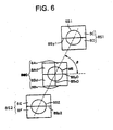
Fig. 6 is a view showing the configuration of the
light receiving portion of the photodetector 8 shown in
Fig. 5.
The photodetector 8 comprises a main light receiving
portion 8S0 and the first and second sub light receiving
portions 8S1 and 8S2. Each of the light receiving
portions 8S0-8S2 is divided in the direction in response
to the track direction of the optical disk 80 and is
divided as the push-pull signals in the disk radial
direction or any signals in response to the push-pull
signals are detectable.
The main light receiving portion 8S0 is divided into
four of the same or approximately same parts by the two
dividing lines 8Sx0, 8Sy0 crossing at right angle and
comprises four division areas 8Au, 8Ad, 8Bu, 8Bd. In the
main light receiving portion 8S0 shown in Fig. 6, the
main light spot MS is formed by (the reflected light of)
the main laser beam from the cylindrical lens 7.
The division area 8Au generates the output signal SAu
in response to the light quantity (the reflected light
quantity) of the main laser beam provided for the area
8Au.
The division area 8Ad generates the output signal SAd
in response to the light quantity of the main laser beam
provided for the area BAd.
The division area 8Bu generates the output signal SBu
in response to the light quantity of the main laser beam
provided for the area 8Bu.
The division area 8Bd generates the output signal SBd
in response to the light quantity of the main laser beam
provided for the area 8Bd.
The direction of the optical axis of the cylindrical
lens 7 is at an angle of about 45° or about 135° to the
direction or the dividing line 8Sx0 or the dividing line
8Sy0 of the main light receiving portion 8S0. The
dividing line 8Sy0 (or the dividing line 8Sx0) of the
main light receiving portion 8S0 for which the main laser
beam reflected at the optical disk 80 is provided is
parallel or approximately parallel to the track direction
of the optical disk 80, and divides the main light
receiving portion 8S0 into two of the same or
approximately same parts.
The cross point of the dividing lines 8Sx0 and 8Sy0
is in the center part or in the approximately center part
of the main laser beam passing through the cylindrical
lens 7.
The shape of the light spot MS formed at the main
light receiving portion 8S0 changes diagonally in
accordance with the distance between the optical disk 80
and the objective lens 2, so that the focus eccentricity
at the optical disk 80 is detectable based on the output
signals SAu, SAd, SBu, and SBd generated by the division
areas 8Au, 8Ad, 8Bu and 8Bd using the astigmatic method.
Note that, the angle defined by the line formed by the
centers of the light receiving portions 8S0-8S2 and the
dividing line 8Sy0 corresponds to said direction β.
The first sub light receiving portion 8S1 is divided
two of the same or approximately same parts by the
dividing line 8Syl and comprises two division areas 8C,
8D. In the first sub light receiving portion 8S1 show in
Fig. 6, the sub light spot SS1 is formed by (the
reflected light of) the first sub laser beam from the
cylindrical lens 7.
The division area 8C generates the output signal SC
in response to the light quantity (the reflected light
quantity) of the sub laser beam provided for the area 8C.
The division area 8D generates the output signal SD in
response to the light quantity (the reflected light
quantity) of the sub laser beam provided for the area 8D.
The center part of the first sub light receiving
portion 8S1 is in the center or approximately center of
the first sub laser beam passing through the cylindrical
lens 7.
The second sub light receiving portion 8S2 is divided
two of the same or approximately same parts by the
dividing line 8Sy2 and comprises two division areas 8E,
8F. In the first sub light receiving portion 8S1 show in
Fig. 6, the sub light spot SS2 is formed by (the
reflected light of) the second sub laser beam from the
cylindrical lens 7.
The division area 8E generates the output signal SE
in response to the light quantity (the reflected light
quantity) of the sub laser beam provided for the area 8E.
The division area 8F generates the output signal SF in
response to the light quantity (the reflected light
quantity) of the sub laser beam provided for the area 8F.
The center part of the second sub light receiving
portion 8S2 is in the center or approximately center of
the second sub laser beam passing through the cylindrical
lens 7. The dividing lines 8Sy0-8Sy42 are parallel or
approximately parallel each other.
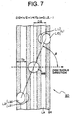
Fig. 7 is a view for explaining the arrangement of
the light spots on the recording side of the optical
disk.
On the recording side of the optical disk 80, the
land LA and the groove GR are formed and the groove GR
forms a track guide groove.
On the recording side of the optical disk 80, the
main light spot MB by the main laser beam having a large
quantity of light and the first and second sub light
spots L1 and L2 by the first and second sub laser beam
having a small quantity of light are formed.
The first sub light spot L1 comprises the spot L10
corresponding to the mainrobe and the spot L11
corresponding to the siderobe.
The second sub light spot L2 comprises the spot L20
corresponding to the mainrobe and the spot L21
corresponding to the siderobe.
The main laser beam is reflected at the main light
spot MB and provided for the main light receiving
portion 8S0 of the photodetector 8.
The first sub laser beam is reflected at the first
sub light spot L1 and provided for the first sub light
receiving portion 8S1 of the photodetector 8. The center
of the sub laser beam reflected at the spot L1 is in the
center or approximately center of the first sub light
receiving portion 8S1.
The second sub laser beam is reflected at the second
sub light spot L2 and provided for the second sub light
receiving portion 8S2 of the photodetector 8. The center
of the sub laser beam reflected at the spot L2 is in the
center or approximately center of the second sub light
receiving portion 8S2.
The light receiving portion 8S0-8S2 of the
photodetector 8 have the configuration which can detects
the push-pull signals in the disk radial direction by the
dividing lines 8Sy0-8Sy2.
The position of two of the sub light spots L1 and L2
on the recording surface of the optical disk 80 are,
preferably, when the main light spot MB is on the track
(for example, when the center part of the main light spot
MB is in the center part of the track), at the position
that when one of the push-pull signals (SC-SD, SE-SF) is
the maximum value, another of the push-pull signals
becomes the minimum value.
The distances from the main light spot MB to two of
the sub light spots L1 and L2 on the optical disk 80 are
same and determined by the angle a mentioned above.
Further, when the two sub light spots L1 and L2 are
at the desired positions, the direction β is formed as
the phase distribution, which are equal to or
approximately equal to the phase distribution generated
to the two sub light spots L1 and L2 by the tilt of the
disk substrate in the disk radial direction, are given.
Namely, the distances D12 from the center part of the
main light spot MB to the center parts of the two sub
light spots L1 and L2 in the disk radial direction is
expressed in the next equation (5) by using the pitch Tp
of the grooves GR (or the track pitch) and an integer n
of 0 or more.
D12 = (n / 2 + 1 / 4) Tp
Especially, in the case the land groove configuration
whose ratio of the width of the land LA and groove GR is
1:1, the center parts of the sub light spots L1 and L2
are arranged at the boundary or the approximately
boundary between the land LA and the groove GR.
The tilt error signal TS indicating the tilt of the
optical disk 80 can be obtained from the sum (PP1+PP2) of
the push-pull signals PP1 and PP2 obtained from the
output signals of the first and second sub light
receiving part 8S2, 8S2 shown in Fig. 6.
The push-pull signal of first sub laser beam is
PP1=SC-SD, the push-pull signal of the second sub laser
beam is PP2=SE-SF, and the tilting error signal is
expressed by the next equation (6).
Note that, the push-pull signal PPO obtained from the
output signal of the main light receiving portion 8S0 is
PP0=SAu+SAd-SBu-SBd and useable as the tracking error
signal TE.
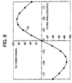
Fig. 8 is a view for explaining the relationship
between the tilt error signal TS and the tilting angle.
Here, the values of each parameters are like this
=0.75°, NA=0.6, λ=405nm, t=0.6mm and Tp=0.7µm.
As shown in Fig. 8, the tilt error signal TS becomes
0 when the tilting angle in the disk radial direction is
0° and has a typical linearity. Further its sign is
inversed in response to the sign of the tilting angle and
desired characteristics are obtained.
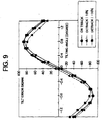
Fig. 9 is a view for explaining the relationships
between the tilt error signal TS and the tilting angle in
the cases the tracking error exists (detrack state) and
non-exists (on track state).
The black circles indicate the case the quantity of
the detrack is 0.
The black triangles indicate the case the quantity of
the detrack is 10% and the case the tracking error of
about 10% of the size of the sub light spot occurs.
The black squares indicate the case the quantity of
the detrack is -10% and the case the tracking error of
about -10% of the size of the sub light spot occurs.
As shown in Fig. 9, In the tilt error signal TS, when
the 10% of detrack occurs, the tilting angle in the disk
radial direction changes about 0.05°, the ratio of the
change is small, and the desired characteristic is
obtained.
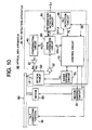
Fig. 10 is a block diagram showing the configuration
of an embodiment of the optical disk apparatus comprising
the optical pickup shown in Fig. 5.
This optical disk apparatus 90 comprises a motor 30,
a motor driving circuit 35, a tilt correcting portion 36,
a compensation circuit 40, an amplifier 42, an optical
pickup 50, an amplifier (head amplifier) 52, a laser
driving circuit 55, a signal generation circuit 60, an
information detection circuit 65, a tilt detection
circuit 66, and a control circuit 70. This optical disk
apparatus 90 reproduces the recording information
recorded on the optical disk 80.
Further, the optical disk apparatus 90 comprises an
tilt detection apparatus 95. This tilt detection
apparatus 95 comprises the compensation circuit 40,
amplifier 42, the optical pickup 50, the amplifier 52,
the laser driving circuit 55, the signal generation
circuit 60, the information detection circuit 65, the
tilt detection circuit 66, and the control circuit 70.
The control circuit 70 is a controller engaged in the
controlling the whole of the optical disk apparatus 90
and includes, for example, a microcomputer.
This control circuit 70 controls the motor 30, the
motor driving circuit 35, the laser driving circuit 55,
the optical pickup 50, the compensation circuit 40, the
information detection circuit 65, the tilt detection
circuit 66 and so on.
The optical pickup 50 exposes the laser beam LB to
the reproducing point of the optical disk 80 when
reproducing.
The laser driving circuit 55 generates a driving
signal SL under the control of the control circuit 70 and
drives the semiconductor laser 4 in the optical pickup 50
by the driving signal to make the semiconductor laser 4
expose the laser beam LB.
The motor 30 is, for example, a spindle motor and
rotates the optical disk 80 at the predetermined rotation
velocity. This motor 30 rotates the optical disk 80
,for example, as the linear velocity becomes constant.
speed.
The motor driving circuit 35 provides the driving
power for the motor 30 to drive the motor 30. This motor
driving circuit 35 may controls the rotation of the motor
30 by the PWM (Pulse Width Modulation) control and may
controls it by the PLL (Phase Locked Loop) control.
The amplifier 52 amplifies each of the output signals
SAu, SAd, SBu and SC-SF from the light receiving portions
of the photodetector 8 comprised the optical pickup 50 to
provide them for the signal generation circuit 60.
The signal generation circuit 60 generates a
reproducing signal RF0 in response to the quantity of the
reflected beam of the main laser beam, the push-pull
signals PP1 and PP2 of the first and second sub laser
beams, the focus error signal FE, and the tracking error
signal TE based on the amplified output signals SAu, SAd,
SBu, SBd, and SC-SF from the amplifier 52.
The signal generation circuit 60 generates the
reproducing signal RF0 (=SAu+SAd+SBu+SBd) based on the
sum of the output signals SAu, SAd, SBu, and SBd from the
amplifier 52.
Further, it generates the push-pull signal PP1 (=SC-SD)
based on the differences of the output signals SC and
SD from the amplifier 52.
Further, it generates the push-pull signal PP1 (=SE-SF)
based on the differences of the output signals SE and
SF from the amplifier 52.
Further, the signal generation circuit 60 generates
the focus error signal FE (=SAu+SBd-SAd-SBu) by the
astigmatic method, for example, based on the difference
of the output signals SAu, SAd, SBu, and SBd in the
diagonal direction.
Note that, the signal generation circuit 60 generates
the push-pull signal PP0 (=SAu+SAd-SBd-SBu) of the main
laser beam and makes the push-pull signal PP0 the
tracking error signal TE.
the compensation circuit 40 compensates the focus
error signal FE and the tracking error signal TE (the
phase compensation and/or the frequency compensation) to
generate a compensation signal and provided the
compensation signal for the amplifier 42.
The amplifier 42 amplifies the compensation signal of
the focus error signal FE to generates the driving signal
Sfe and provides it for the focusing actuator 2F in the
optical pickup 50.
Further, the amplifier 42 amplifies the compensation
signal of the tracking error signal TE to generates the
driving signal Ste and provides it for the tracking
actuator 2T in the optical pickup 50.
The tilt detection circuit 66 detects the tilt or the
tilting angle based on the sum of the push-pull signals
PP1 and PP2. Concretely, it generates a tilt error signal
TS (=PP1+PP2) corresponding to the tilt angle based on
the sum of the push-pull signals PP1 and PP2 and it
provides the tilt error signal TS for the control circuit
70.
The information detection circuit 65 is provided the
reproducing signal RF0 from the signal generation circuit
60, carries out the demodulation of the reproducing
signal RF0 and so on, and outputs the reproduced
recording information as an output signal So.
Further, the information detection circuit 65 detects
an address of the optical disk 80 from the reproducing
signal RF0 and reproduces the recording information based
on the address.
The control circuit 70 generates a cross track signal
CT (=PP1-PP2) based on the push-pull signals PP1 and PP2
and detects whether the position of the light spot of the
main laser beam is on the track or not based on the
signal CT. The cross track signal CT is referred, for
example, when the light spot cross the track as seeking.
The tilt correcting portion 36 corrects the tilt of
the optical disk 80. For example, the control circuit 70
controls the tilt correcting portion 36 based on the tilt
error signal TS by the close loop control. The tilt
correcting portion 36 corrects the tilt under the control
of the control circuit 70 so that the tilt error signal
TS becomes 0.
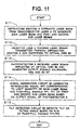
Fig. 11 is a flow-chart showing the detection method
for detecting the tilt in the radial direction or the
optical disk 80 in the tilt detection apparatus 95 of the
optical disk apparatus 90.
First, in the step S111, the diffraction grating 9 of
the optical pickup 50 diffracts the laser beam from the
semiconductor laser 4 to generate the main laser beam
including the 0th order diffraction beam and first and
second sub laser beams each including +-first diffraction
beams.
The first ane second sub laser beams have a phase
distribution equal to or substantially equal to the phase
distribution due to the wave front aberration generated
on the optical disk 80 when the optical disk 80 is
tilted.
These laser beams ( the main laser beam and the first
and second sub laser beams) is provided for the objective
lone 2 passing through the beam splitter 3.
In the step S112, the objective lens 2 collects laser
beams (the main laser beam and the first and second sub
laser beams) from the diffraction grating 9 to provide
them to the optical disk 80 to expose the laser beams on
the optical disk 80. The objective lens2 collects the
main laser beam to expose the track of the optical disk
80.
The main laser beam collected by the objective lens2
are reflected at the optical disk 80, passes through the
objective lens 2 again, and are provided the
photodetector 8 passing through the beam splitter 3, the
collecting lens 6, and the cylindrical lens 7.
In the step S113, the photodetector 8 receives the
main laser beam and the first and second laser beam
reflected at the optical disk 80 at the light receiving
portions 8S0-8S2 to generate the output signals SAu, SAd,
SBu, SBd, and SC-SF. Theses output signals are provided
for the signal generation circuit 60 via the amplifier
(head amplifier) 52.
In the step S114, the signal generation circuit 60
generates the reproducing signal RF in response to the
quantity of the reflected main laser beam, the push-pull
signals PP1 and PP2 of the first and second sub laser
beams based on the output signals SAu, SAd, SBu, SBd, and
SC-SF. Note that, the reproducing signal RF0 is provided
for the information detection circuit 65 and the
recording information is extracted.
In the step S115, the tilt detection circuit 66
detects the tilt or the tilting angle of the optical disk
80 based on the sum of the push-pull signals pp1 and PP2
of the first and second sub laser beams. Concretely,
based on the sum of the push-pull signals PP1 and PP2, it
generates the tilt error signal TS (=PP1+PP2) in response
to the tilting angle of the optical disk 80.
The method for detecting the tilt of the optical disk
as mentioned above is effective when the eccentricity of
the optical disk is small.
When the eccentricity of the optical disk is large,
the objective lens2 is transferred in the disk radial
direction in response to the eccentricity, the light spot
on the light receiving portion is moved, and the offset
occurs on the tilt error signal TS in response to the
eccentricity.
For the above reason, it is preferable to remove the
offset due to the eccentricity from the tilt error signal
TS.
To remove the offset due to the eccentricity from the
tilt error signal TS, another diffraction grating is
added to the optical pickup 50. And predetermined
operation is carried out using the diffraction beams
generated by the added diffraction grating.
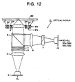
Fig. 12 is a view of the configuration of the optical
pickup 51 formed by adding the diffraction grating 11 to
the optical pickup 50.
Further, in the optical pickup 51 shown in Fig. 12,
the same portions as the optical pickup 50 shown in Fig.
5 are given the same references and the explanation of
them are suitably omitted.
This optical pickup 51 comprises a semiconductor
laser 4, a collimator lens 5, a diffraction grating 9, a
diffraction grating 11, a beam splitter 3, an object lens
2, a collecting lens 6, cylindrical lens 7, a
photodetector 18, lens holders 2H, a focusing actuator 2F
and a tracking actuator 2T.
The semiconductor laser 4 outputs a linearly
polarized laser beam based on the driving signal SL and
provides it for the collimator lens 5.
The collimator lens 5 collimates the laser beam from
the semiconductor laser 4 and provided it for the
diffraction grating 9.
The diffraction grating 9 divides the laser beam from
the collimator lens 5 into the main laser beam including
0th order diffraction beam and the first and second sub
laser beams including +-first order diffraction beams and
provides these laser beams (the main laser beam and the
first and second sub laser beams) for the diffraction
grating 11.
The diffraction grating 11 comprises, for example, a
glass substrate on which straight and parallel grooves
are formed and diffracts the laser beams from the
diffraction grating 9. And then, it generates 0th order
diffraction beam and +-first order diffraction beams of
each of the laser beams to provide them for the beam
splitter 3.
Concretely, the diffraction grating 11 generates a
main laser diffraction beam which is a 0th order
diffraction beam of the main laser beam from the
diffraction grating 9 and third and forth sub laser
diffraction beams which are +-first order diffraction
beams of the main laser beam.
Further, the diffraction grating 11 generates a first
sub laser diffraction beam which is a 0th order
diffraction beam of the first sub laser beam from the
diffraction grating 9 and +-first diffraction beams of
the first sub laser beam.
Further, the diffraction grating 11 generates a
second sub laser diffraction beam which is a 0th order
diffraction beam of the second sub laser beam from the
diffraction grating 9 and +-first diffraction beams of
the second sub laser beam.
Further, the light intensities of the +-first
diffraction beams of the first and second sub laser beams
are as small as to ignore them in comparison with the
main laser diffraction beam and the third and forth sub
laser diffraction beams.
The beam splitter 3 passes through the laser beams
from the diffraction grating 9 and 11 and provides them
for the objective lens 2.
The objective lens 2 collects the laser beams from
the beam splitter 3 and provides them for the optical
disk 80 formed lands and/or grooves.
Further, the objective lens 2 returns the laser beams
reflected at the optical disk 80 to the beam splitter 3.
The beam splitter 3, to which the laser beams from
the objective lens 2 are exposed, reflects and outputs
the exposed laser beams and provides them for the
collecting lens 6.
The collecting lens 6 collects the laser beams from
the beam splitter 3 and provides them for the cylinder-shaped
lens (cylindrical lens) 7.
The cylindrical lens 7 passes through the laser beams
from the collecting lens 6 and provides them for the
photodetector 18.
The photodetector 18 receives the laser beams (the
main laser diffraction beam and the first to forth sub
laser diffraction beams) from the cylindrical lens 7 at
the light receiving portion and generates output signals
SAu, SAd, SBu, SBd, and SC-SJ.
Fig. 13 is a view showing the configuration of the
light receiving portion of the photodetector 18 shown in
Fig. 12.
The photodetector 18 comprises a main light receiving
portion 8S0 and the first and forth sub light receiving
portions 8S1-8S4. Each of the light receiving portions
8S0-8S4 is divided in the direction in response to the
track direction of the optical disk 80 as the push-pull
signals in the disk radial direction or any signals in
response to the push-pull signals are detectable.
The main light receiving portion 8S0 is divided into
four of the same or approximately same parts by the two
division lines 8Sx0, 8Sy0 crossing at right angle and
comprises four division areas 8Au, 8Ad, 8Bu, 8Bd. In the
main light receiving portion 8S0 shown in Fig. 13, the
main light spot MS is formed by (the reflected light of)
the main laser beam from the cylindrical lens 7.
The division area 8Au generates the output signal SAu
in response to the light quantity (the reflected light
quantity) of the main laser beam provided for the area
8Au.
The division area 8Ad generates the output signal SAd
in response to the light quantity of the main laser beam
provided for the area 8Ad.
The division area 8Bu generates the output signal SBu
in response to the light quantity of the main laser beam
provided for the area 8Bu.
The division area 8Bd generates the output signal SBd
in response to the light quantity of the main laser beam
provided for the area 8Bd.
The direction of the optical axis of the cylindrical
lens 7 is at an angle of about 45° or about 135° to the
direction of the division line 8Sx0 or the division line
8Sy0 of the main light receiving portion 8S0. The
division line 8Sy0 (or the division line 8Sx0) of the
main light receiving portion 8S0 for which the main laser
diffraction beam reflected at the optical disk 80 is
provided is parallel or approximately parallel to the
track direction of the optical disk 80, and divides the
main light receiving portion 8S0 into two of the same or
approximately same parts.
The cross point of the division lines 8Sx0 and 8Sy0
is in the center part or in the approximately center part
of the main laser diffraction beam passing through the
cylindrical lens 7.
The shape of the light spot MS formed at the main
light receiving portion 8S0 changes diagonally in
accordance with the distance between the optical disk 80
and the objective lens 2, so that the focus eccentricity
at the optical disk 80 is detectable based on the output
signals SAu, SAd, SBu, and SBd generated by the division
areas 8Au, 8Ad, 8Bu and 8Bd using the astigmatic method.
Note that, the angle defined by the line formed by the
light receiving portions 8S0-8S2 and the division line
8Sy0 corresponds to said direction β.
The first sub light receiving portion 8S1 is divided
two of the same or approximately same parts by the
division line 8Sy1 and comprises two division areas 8C,
8D. In the first sub light receiving portion 8S1 shown in
Fig. 13, the sub light spot SS1 is formed by the first
sub laser diffraction beam from the cylindrical lens 7.
The division area 8C generates the output signal SC
in response to the light quantity (the reflected light
quantity) of the sub laser diffraction beam provided for
the area 8C. The division area 8D generates the output
signal SD in response to the light quantity (the
reflected light quantity) of the sub laser diffraction
beam provided for the area 8D.
The center part of the first sub light receiving
portion 8S1 is in the center or approximately center of
the first sub laser diffraction beam passing through the
cylindrical lens 7.
The second sub light receiving portion 8S2 is divided
two of the same or approximately same parts by the
division line 8Sy2 and comprises two division areas 8E,
8F. In the second sub light receiving portion 8S2 show in
Fig. 13, the sub light spot SS2 is formed by (the
reflected light of) the second sub laser diffraction beam
from the cylindrical lens 7.
The division area 8E generates the output signal SE
in response to the light quantity (the reflected light
quantity) of the sub laser diffraction beam provided for
the area 8E. The division area 8F generates the output
signal SF in response to the light quantity (the
reflected light quantity) of the sub laser diffraction
beam provided for the area 8F.
The center part of the second sub light receiving
portion 8S2 is in the center or approximately center of
the second sub laser diffraction beam passing through the
cylindrical lens 7.
The third sub light receiving portion 8S3 is divided
two of the same or approximately same parts by the
division line 8Sy3 and comprises two division areas 8G,
8H. In the third sub light receiving portion 8S3 show in
Fig. 13, the sub light spot SS3 is formed by (the
reflected light of) the third sub laser diffraction beam
from the cylindrical lens 7.
The division area 8G generates the output signal SG
in response to the light quantity (the reflected light
quantity) of the sub laser diffraction beam provided for
the area 8G. The division area 8H generates the output
signal SH in response to the light quantity (the
reflected light quantity) of the sub laser diffraction
beam provided for the area 8G.
The center part of the third sub light receiving
portion 8S3 is in the center or approximately center of
the third sub laser diffraction beam passing through the
cylindrical lens 7.
The forth sub light receiving portion 8S4 is divided
two of the same or approximately same parts by the
division line 8Sy4 and comprises two division areas 8I,
8J. In the forth sub light receiving portion 8S4 show in
Fig. 13, the sub light spot SS4 is formed by (the
reflected light of) the forth sub laser diffraction beam
from the cylindrical lens 7.
The division area 8I generates the output signal SI
in response to the light quantity (the reflected light
quantity) of the sub laser diffraction beam provided for
the area 8I. The division area 8J generates the output
signal SJ in response to the light quantity (the
reflected light quantity) of the sub laser diffraction
beam provided for the area 8J.
The center part of the forth sub light receiving
portion 8S4 is in the center or approximately center of
the forth sub laser diffraction beam passing through the
cylindrical lens 7. The division lines 8Sy0-8Sy4 are
parallel or approximately parallel each other.
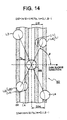
Fig. 16 is a view for explaining the arrangement of
the light spots on the recording side of the optical
disk.
On the recording side of the optical disk 80, the
land LA and the groove GR are formed and the groove GR
forms a track guide groove.
On the recording side of the optical disk 80, the
main light spot MB by the main laser diffraction beam
having a large quantity of light and the first to forth
sub light spot L1-L4 by the first to forth sub laser
diffraction beams having a small quantity of light are
formed.
The first sub light spot L1 comprises the spot L10
corresponding to the mainrobe and the spot L11
corresponding to the siderobe.
The second sub light spot L2 comprises the spot L20
corresponding to the mainrobe and the spot L21
corresponding to the siderobe.
The main laser diffraction beam is reflected at the
main light spat MS and provided for the main light
receiving portion 8S0 of the photodetector 18.
The first sub laser diffraction beam is reflected at
the first sub light spot L1 and provided for the first
sub light receiving portion 8S1 of the photodetector 18.
The center of the sub laser diffraction beam reflected at
the spot L1 is in the center or approximately center of
the first sub light receiving portion 8S1.
The second sub laser diffraction beam is reflected at
the second sub light spot L2 and provided for the second
sub light receiving portion 8S2 of the photodetector 18.
The center of the sub laser diffraction beam reflected at
the spot L2 is in the center or approximately center of
the second sub light receiving portion 8S2.
The third sub laser diffraction beam is reflected at
the third sub light spot L3 and provided for the third
sub light receiving portion 8S3 of the photodetector 18.
The center of the sub laser diffraction beam reflected at
the spot L3 is in the center or approximately center of
the third sub light receiving portion 8S3.
The forth sub laser diffraction beam is reflected at
the forth sub light spot L4 and provided for the forth
sub light receiving portion 8S4 of the photodetector 18.
The center of the sub laser diffraction beam reflected at
the spot L4 is in the center or approximately center of
the forth sub light receiving portion 8S4.
The light receiving portion 8S0-8S4 of the
photodetector 18 have the configuration which can detects
the push-pull signals in the disk radial direction by the
division lines 8Sy0-8Sy4.
The distances from the main light spot MB to two of
the sub light spots L1 and L2 on the optical disk 80 are
same and determined by the angle α mentioned above.
Further, when the two sub light spots L1 and L2 are
at the desired positions, the direction β is formed as
the phase distribution, which are equal to or
approximately equal to the phase distribution generated
to the two sub light spots L1 and L2 by the tilt of the
disk substrate in the disk radial direction, are given.
Namely, the distances D12 from the center part of the
main light spot MB to the center parts of the two sub
light spots L1 and L2 in the disk radial direction is
expressed in the equation (5) mentioned above by using
the pitch Tp of the grooves GR and an integer n of 0 or
more.
Further, the distances D34 from the center part of
the main light spot MB to the center parts of the two sub
light spot L3, L4 in the disk radial direction is
expressed in the next equation (7) by using the pitch Tp
of the grooves GR and an integer m of 0 or more.
D34 = (m + 1 / 2) Tp
Especially, in the case the land groove configuration
whose ratio of the width of the land LA and groove GR is
1:1, the center parts of the sub light spots L1 and L2
are arranged at the center or approximately center of the
groove GR.
The eccentricity signal RO in response to the
eccentricity of the optical disk 80 is calculated by the
next equation (8) based on the push-pull signal PP0 of
the main laser diffraction beam and the push-pull signals
PP3 and PP4 of the third and forth sub laser diffraction
beams.
In the above equation (8), by correcting the
difference of the light intensity between the main spot
MS of the main light receiving portion 8S0 and the sub
spots SS3 and SS4 of the sub light receiving portion 8S3
and 8S4 by a coefficient k, the eccentricity signal RO
can be detected because the polarity between the push-pull
element PPO and the push-pull element PP3 and PP4 is
opposite. This correction coefficient k is expressed by
the next equation (9).
Therefore, by subtracting the signal (k0×R0) of the
result of the multiplication of the eccentricity signal
RO and a reasonable coefficient k0 from the tilt error
signal TS, the tilt error signal TS0 removed the offset
due to the eccentricity can be obtained.
This tilt error signal TS0 is expressed by the next
equation (10).
Further, the correction coefficient k0 for correcting
the light intensity of the main light spot MS and the sub
light spots SS1 and SS2 is expressed by the next equation
(11).
Fig. 15 is a view for explaining the relationships
between the tilt error signal TS and the tilting angle
when the both cases the eccentricity exists and doesn't
exist in accordance with the Fig. 8 and Fig. 9.
The black circles indicate the case the quantity of
the eccentricity is 0.
The black squares indicate the case the quantity of
the eccentricity is 20%, which is the case the
eccentricity of about 20% of the size of the objective
lens 2 occurs.
As shown in Fig. 15, even though the eccentricity
occurs, the desired characteristic of the tilt error
signal TS0 is obtained.
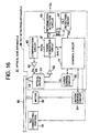
Fig. 16 is a block diagram showing the configuration
of an embodiment of the optical disk apparatus comprising
the optical pickup 51 shown in Fig. 12.
Further, in the optical disk apparatus 91 shown in
Fig. 16, the same portions as the optical disk apparatus
90 shown in Fig. 10 are given the same references and the
explanation of them are suitably omitted.
This optical disk apparatus 91 comprises a motor 30,
a motor driving circuit 35, a tilt correcting portion 36,
a compensation circuit 40, an amplifier 42, an optical
pickup 51, an amplifier (head amplifier) 53, a laser
driving circuit 55, a signal generation circuit 60, an
information detection circuit 65, a tilt detection
circuit 67, and a control circuit 71.
Further, the optical disk apparatus 91 comprises an
tilt detection apparatus 96. This tilt detection
apparatus 96 comprises the compensation circuit 40, the
amplifier 42, the optical pickup 51, the amplifier 53,
the laser driving circuit 55, the signal generation
circuit 61, the information detection circuit 65, the
tilt detection circuit 67, and the control circuit 71.
The control circuit 71 is a controller engaged in the
controlling the whole of the optical disk apparatus 91
and includes, for example, a microcomputer.
This control circuit 71 controls the motor 30, the
motor driving circuit 35, the laser driving circuit 55,
the optical pickup 51, the compensation circuit 40, the
signal generation circuit 61, the information detection
circuit 65, the tilt detection circuit 67 and so on.
The optical pickup 51 exposes the laser beam LB to
the reproducing point of the optical disk 80 when
reproducing.
The laser driving circuit 55 generates a driving
signal SL under the control of the control circuit 71 and
drives the semiconductor laser 4 in the optical pickup 51
by the driving signal to make the semiconductor laser 4
expose the laser beam LB.
The amplifier 53 amplifies each of the output signals
SAu, SAd, SBu, SBd and SC-SJ from the light receiving
portions of the photodetector 18 comprised the optical
pickup 51 to provide them for the signal generation
circuit 61.
The signal generation circuit 61 generates a
reproducing signal RF0 in response to the quantity of the
reflected beam of the main laser diffraction beam and
reproducing signals RF1-RF4 in response to the quantity
of the reflected beams of the first to forth sub laser
diffraction beams based on the amplified output signals
SAu, SAd, SBu, SBd, and SC-SJ from the amplifier 53.
Further, the signal generation circuit 61 generates
the push-pull signal PP0 of the main laser diffraction
beam and the push-pull signals PP1-PP4 of the first to
forth sub laser diffraction signals.
Further, the signal generation circuit 61 generates
the focus error signal FE and the tracking error signal
TE.
The signal generation circuit 61 generates the
reproducing signal RF0 (=SAu+SAd+SBu+SBd) based on the
sum of the output signals SAu, SAd, SBu, and SBd from the
amplifier 53.
Further, it generates the reproducing signal RF1
(-SC+SD) based on the output signals SC and SD.
Further, it generates the reproducing signal RF2
(=SE+SF) based on the output signals SE and SF.
Further, it generates the reproducing signal RF3
(=SG+SH) based on the output signals SG and SH.
Further, it generates the reproducing signal RF4
(=SI+SJ) based on the output signals SI and SJ.
Further, the signal generation circuit 61 generates
the push-pull signal PP0 (=SAu+SAd-SBu-SBd), for example,
based on the difference of the output signals SAu, SAd
and the output signals SBu, SBd from the amplifier S3.
Further, it generates the push-pull signal PP1 (=SC-SD)
based on the difference of the output signal SC and
SD.
Further, it generates the push-pull signal PP2 (=SE-SF)
based on the difference of the output signal SE and
SF.
Further, it generates the push-pull signal PP3 (=SG-SH)
based on the difference of the output signal SG and
SH.
Further, it generates the push-pull signal PP4 (=SI-SJ)
based on the difference of the output signal SI and
SJ.
Further, the signal generation circuit 61 generates
the focus error signal FE (=SAu+SBd-SAd-SBu) by the
astigmatic method, for example, based on the difference
of the output signals SAu, SAd, SBu, and SBd from the
amplifier 53 in the diagonal direction.
Note that, the signal generation circuit 61 makes the
push-pull signal PP0 the tracking error signal TE.
The tilt detection circuit 67 detects the tilt or the
tilting angle based on the sum of the push-pull signals
PP1 and PP2 and the eccentricity element. Concretely, it
generates a tilt error signal TSO corresponding to the
tilt angle based on the difference of the sum of the
push-pull, signals PP1 and PP2 and the eccentricity signal
RO and it provides the generated tilt error signal TSO
for the control circuit 71.
The information detection circuit 65 is provided the
reproducing signal RF0 from the signal generation circuit
61, carries out the demodulation of the reproducing
signal RF0 and so on to reproduce the recording
information of the optical disk 80, and outputs the
reproduced recording information as an output signal So.
Further, the information detection circuit 65 detects
an address of the optical disk 80 from the reproducing
signal RF0 and reproduces the recording information based
on the address.
The control circuit 71 generates a cross track signal
CT (=PP1-PP2) based on the push-pull signals PP1 and PP2
and detects whether the position of the light spot of the
main laser beam is on the track or not based on the
signal CT. The cross track signal CT is referred, for
example, when the light spot cross the track as seeking.
The tilt correcting portion 36 corrects the tilt of
the optical disk 80. For example, the control circuit 71
controls the tilt correcting portion 36 based on the tilt
error signal TS0 by the close loop control. The tilt
correcting portion 36 corrects the tilt under the control
of the control circuit 71 so that the tilt error signal
TS becomes 0.
Fig. 17 is a flow-chart showing the detection method
for detecting the tilt in the radial direction of the
optical disk 80 in the tilt detection apparatus 96 of the
optical disk apparatus 91.
First, in the step S121, the diffraction grating 9 of
the optical pickup 51 diffracts the laser beam from the
semiconductor laser 4 to generate the main laser beam
including a 0th order diffraction beam and first and
second sub laser beams each including +-first diffraction
beams.
Each of the first and second sub laser beams have a
phase distribution equal to or substantially equal to the
phase distribution due to the wave front aberration
generated on the optical disk 80 when the optical disk 80
is tilted.
These laser beams (the main laser beam and the first
and second sub laser beams) are provided for the
diffraction grating 11.
In the step S122, the diffraction grating 11
diffracts the main laser beam from the diffraction
grating 9 to generate the main laser diffraction beam
including a 0th order diffraction beam and third and
forth sub laser diffraction beams each including +-first
diffraction beam.
Further, the diffraction grating 11 diffracts the
first sub laser beam from the diffraction grating 9 to
generate the first laser diffraction beam including a 0th
order diffraction beam and diffracts the second sub laser
beam from the diffraction grating 9 to generate the
second laser diffraction beam including a 0th order
diffraction beam.
These laser beams (the main laser diffraction beam
and the first to forth sub laser diffraction beams) are
provided for the objective lens 2 passing through the
beam splitter 3.
Note that, each of the first and second sub laser
diffraction beam has a phase distribution equal to or
approximately equal to the phase distribution due to the
wave front aberration generated on the optical disk 80
when the optical disk 80 is tilted.
In the step S123, the objective lens 2 collects laser
beams (the main laser diffraction beam and the first to
forth sub laser diffraction beams) from the diffraction
grating 9 and 11 and provides them to the optical disk 80
to expose the laser beams on the optical disk 80. The
objective lens 2 collects the main laser diffraction beam
to expose the track of the optical disk 80.
The main laser beam collected by the objective lens 2
are reflected at the optical disk 80, passes through the
objective lens 2 again, and are provided for the
photodeteotor 18 passing through the beam splitter 3, the
collecting lens 6, and the cylindrical lens 7.
In the step S124, the photodetector 18 receives the
main laser diffraction beam and the first to forth laser
diffraction beams reflected at the optical disk 80 at the
light receiving portions 8S0-8S4 to generate the output
signals SAu, SAd, SBu, SBd, and SC-SJ. Theses output
signals are provided for the signal generation circuit 61
via the amplifier (head amplifier) 53.
In the step S125, the signal generation circuit 61
generates the reproducing signals RF0 and RF1-RF4 in
response to the quantities of the reflected main laser
diffraction beam and the first to forth sub laser
diffraction beams
based on the output signals SAu, SAd, SBu, SBd and SC-SJ.
Further, the signal generation circuit 61 generates
the push-pull signals PP0 and PP1-PP4 of the main laser
diffraction beam and the first to forth sub laser
diffraction beams.
In the step S126, the tilt detection circuit 67
detects the tilt or the tilting angle of the optical disk
80 based on the difference of the push-pull signals PP1
and PP2 and the first and second sub laser diffraction
beams and the eccentricity signal RO. Concretely, the
tilt error signal TSO (=PP1+PP2-k0×RO) corresponding to
the tilting angle of the optical disk 80 is generated
based on the difference of the push-pull signals PP1 and
PP2 and the eccentricity signal RO.
The optical pickup 51 with the configuration as
mentioned above can detect the tilt of the optical disk
when the optical disk is eccentric.
Note that, the present invention is not limited to
the above embodiments and includes modifications within
the scope of the claims.
For example, in the optical pickup 51, the
diffraction grating 9 and the diffraction grating 11 the
arrangement may be replaced each other.
Further, in the tilt detection apparatus 95 shown in
Fig. 10, the tilt detection circuit 66 may be formed like
that it detects the eccentricity signal RQ in response to
the eccentricity of the optical disk 80 based on the
detection signal SR from the center point sensor 12 of
the optical pickup 50, generates the tilting error signal
TS' based on the difference of the sum of the push-pull
signals PP1 and PP2 and the eccentricity signal RQ, and
provides the tilt error signal TS' for the control
circuit 70.
For example, it extracts the frequency element in
response to the rotation period of the optical disk 80
from the detection signal SR and generates the
eccentricity signal RQ based on the extracted frequency
element.
In this case, the step of generating the eccentricity
signal RQ is included in the flow-chart shown in Fig. 11
, and in the step S115 the tilt detection circuit 65
detects the tilt or the tilting angle based on the
difference of the sum of the push-pull signals PP1 and
PP2 and the eccentricity signal RQ.
As explained above, according to the present
invention, the tilt detection apparatus and tilt
detection method detectable the tilt of the optical disk
using the diffraction beams, the optical pickup can be
applied to the tilt detection apparatus, and the optical
disk apparatus can be provided.