EP1124226A2 - Lens drive device,suspension unit for lens drive device and method for manufacturing the same - Google Patents
Lens drive device,suspension unit for lens drive device and method for manufacturing the same Download PDFInfo
- Publication number
- EP1124226A2 EP1124226A2 EP01301064A EP01301064A EP1124226A2 EP 1124226 A2 EP1124226 A2 EP 1124226A2 EP 01301064 A EP01301064 A EP 01301064A EP 01301064 A EP01301064 A EP 01301064A EP 1124226 A2 EP1124226 A2 EP 1124226A2
- Authority
- EP
- European Patent Office
- Prior art keywords
- lens holder
- wire
- coil
- tracking
- elastic members
- Prior art date
- Legal status (The legal status is an assumption and is not a legal conclusion. Google has not performed a legal analysis and makes no representation as to the accuracy of the status listed.)
- Granted
Links
- 239000000725 suspension Substances 0.000 title claims abstract description 89
- 238000000034 method Methods 0.000 title claims abstract description 21
- 238000004519 manufacturing process Methods 0.000 title claims abstract description 15
- 229910052751 metal Inorganic materials 0.000 claims abstract description 16
- 239000002184 metal Substances 0.000 claims abstract description 16
- 239000011347 resin Substances 0.000 claims description 29
- 229920005989 resin Polymers 0.000 claims description 29
- 238000000465 moulding Methods 0.000 claims description 6
- 238000005520 cutting process Methods 0.000 claims description 4
- 230000003287 optical effect Effects 0.000 description 29
- 230000005484 gravity Effects 0.000 description 26
- 238000010586 diagram Methods 0.000 description 24
- 230000008878 coupling Effects 0.000 description 17
- 238000010168 coupling process Methods 0.000 description 17
- 238000005859 coupling reaction Methods 0.000 description 17
- 239000000758 substrate Substances 0.000 description 16
- RYGMFSIKBFXOCR-UHFFFAOYSA-N Copper Chemical compound [Cu] RYGMFSIKBFXOCR-UHFFFAOYSA-N 0.000 description 8
- 230000002093 peripheral effect Effects 0.000 description 7
- 239000011889 copper foil Substances 0.000 description 6
- 238000010276 construction Methods 0.000 description 5
- 238000005304 joining Methods 0.000 description 4
- 238000004080 punching Methods 0.000 description 4
- 230000001629 suppression Effects 0.000 description 4
- 239000000463 material Substances 0.000 description 3
- 238000005096 rolling process Methods 0.000 description 3
- 229910052802 copper Inorganic materials 0.000 description 2
- 239000010949 copper Substances 0.000 description 2
- 230000000694 effects Effects 0.000 description 2
- 230000004907 flux Effects 0.000 description 2
- 230000005405 multipole Effects 0.000 description 2
- 238000007747 plating Methods 0.000 description 2
- 229910000906 Bronze Inorganic materials 0.000 description 1
- OAICVXFJPJFONN-UHFFFAOYSA-N Phosphorus Chemical compound [P] OAICVXFJPJFONN-UHFFFAOYSA-N 0.000 description 1
- 235000008331 Pinus X rigitaeda Nutrition 0.000 description 1
- 235000011613 Pinus brutia Nutrition 0.000 description 1
- 241000018646 Pinus brutia Species 0.000 description 1
- 230000002411 adverse Effects 0.000 description 1
- 229910052782 aluminium Inorganic materials 0.000 description 1
- XAGFODPZIPBFFR-UHFFFAOYSA-N aluminium Chemical compound [Al] XAGFODPZIPBFFR-UHFFFAOYSA-N 0.000 description 1
- DMFGNRRURHSENX-UHFFFAOYSA-N beryllium copper Chemical compound [Be].[Cu] DMFGNRRURHSENX-UHFFFAOYSA-N 0.000 description 1
- 239000010974 bronze Substances 0.000 description 1
- KUNSUQLRTQLHQQ-UHFFFAOYSA-N copper tin Chemical compound [Cu].[Sn] KUNSUQLRTQLHQQ-UHFFFAOYSA-N 0.000 description 1
- IUYOGGFTLHZHEG-UHFFFAOYSA-N copper titanium Chemical compound [Ti].[Cu] IUYOGGFTLHZHEG-UHFFFAOYSA-N 0.000 description 1
- 238000013016 damping Methods 0.000 description 1
- 238000003698 laser cutting Methods 0.000 description 1
Images






Classifications
-
- G—PHYSICS
- G11—INFORMATION STORAGE
- G11B—INFORMATION STORAGE BASED ON RELATIVE MOVEMENT BETWEEN RECORD CARRIER AND TRANSDUCER
- G11B7/00—Recording or reproducing by optical means, e.g. recording using a thermal beam of optical radiation by modifying optical properties or the physical structure, reproducing using an optical beam at lower power by sensing optical properties; Record carriers therefor
- G11B7/12—Heads, e.g. forming of the optical beam spot or modulation of the optical beam
- G11B7/22—Apparatus or processes for the manufacture of optical heads, e.g. assembly
-
- G—PHYSICS
- G11—INFORMATION STORAGE
- G11B—INFORMATION STORAGE BASED ON RELATIVE MOVEMENT BETWEEN RECORD CARRIER AND TRANSDUCER
- G11B7/00—Recording or reproducing by optical means, e.g. recording using a thermal beam of optical radiation by modifying optical properties or the physical structure, reproducing using an optical beam at lower power by sensing optical properties; Record carriers therefor
- G11B7/08—Disposition or mounting of heads or light sources relatively to record carriers
- G11B7/09—Disposition or mounting of heads or light sources relatively to record carriers with provision for moving the light beam or focus plane for the purpose of maintaining alignment of the light beam relative to the record carrier during transducing operation, e.g. to compensate for surface irregularities of the latter or for track following
- G11B7/0925—Electromechanical actuators for lens positioning
- G11B7/0932—Details of sprung supports
-
- G—PHYSICS
- G11—INFORMATION STORAGE
- G11B—INFORMATION STORAGE BASED ON RELATIVE MOVEMENT BETWEEN RECORD CARRIER AND TRANSDUCER
- G11B7/00—Recording or reproducing by optical means, e.g. recording using a thermal beam of optical radiation by modifying optical properties or the physical structure, reproducing using an optical beam at lower power by sensing optical properties; Record carriers therefor
- G11B7/08—Disposition or mounting of heads or light sources relatively to record carriers
- G11B7/09—Disposition or mounting of heads or light sources relatively to record carriers with provision for moving the light beam or focus plane for the purpose of maintaining alignment of the light beam relative to the record carrier during transducing operation, e.g. to compensate for surface irregularities of the latter or for track following
- G11B7/0925—Electromechanical actuators for lens positioning
- G11B7/0933—Details of stationary parts
-
- G—PHYSICS
- G11—INFORMATION STORAGE
- G11B—INFORMATION STORAGE BASED ON RELATIVE MOVEMENT BETWEEN RECORD CARRIER AND TRANSDUCER
- G11B7/00—Recording or reproducing by optical means, e.g. recording using a thermal beam of optical radiation by modifying optical properties or the physical structure, reproducing using an optical beam at lower power by sensing optical properties; Record carriers therefor
- G11B7/08—Disposition or mounting of heads or light sources relatively to record carriers
- G11B7/09—Disposition or mounting of heads or light sources relatively to record carriers with provision for moving the light beam or focus plane for the purpose of maintaining alignment of the light beam relative to the record carrier during transducing operation, e.g. to compensate for surface irregularities of the latter or for track following
- G11B7/0925—Electromechanical actuators for lens positioning
- G11B7/0935—Details of the moving parts
-
- G—PHYSICS
- G11—INFORMATION STORAGE
- G11B—INFORMATION STORAGE BASED ON RELATIVE MOVEMENT BETWEEN RECORD CARRIER AND TRANSDUCER
- G11B7/00—Recording or reproducing by optical means, e.g. recording using a thermal beam of optical radiation by modifying optical properties or the physical structure, reproducing using an optical beam at lower power by sensing optical properties; Record carriers therefor
- G11B7/08—Disposition or mounting of heads or light sources relatively to record carriers
- G11B7/09—Disposition or mounting of heads or light sources relatively to record carriers with provision for moving the light beam or focus plane for the purpose of maintaining alignment of the light beam relative to the record carrier during transducing operation, e.g. to compensate for surface irregularities of the latter or for track following
- G11B7/0925—Electromechanical actuators for lens positioning
- G11B7/093—Electromechanical actuators for lens positioning for focusing and tracking
Definitions
- the present invention relates to a lens drive device for writing or reading information optically to or from a disk-shaped recording medium such as a compact disk or an optical disk and its manufacturing method.
- the pickup drive device 1 for reproducing the information which has been recorded in an optical disk such as the CD or the DVD.
- the pickup drive device performs: a focusing control to control the distance between the information recorded face and an objective lens against the warpage or deviation of the optical disk; and a tracking control to follow and control an objective lens with respect to the eccentricity of the information track of the optical disk.
- the conventional pickup device is constructed to include a lens holder and a moving unit having focusing coils, tracking coils and so on.
- the coils are fixed on the lens holder and are then electrically connected.
- the pickup device has a problem that the manufacturing works are complicated to take a long time.
- the leader wires are led around in the space near the lens holder.
- the leader wires come into contact with another member at the time of driving the lens holder so that brokage of leader wires may occur.
- the invention has been conceived in view of the above-specified problems and has an object to provide a lens drive device, in which a lens holder forming a moving unit and connection wires for connecting a plurality of drive coils electrically are integrally molded, and a method for manufacturing the lens drive device.
- a lens drive device comprising a lens holder to which an objective lens and a plurality of drive coils are fixed, and a plurality of wire-form elastic members made of a metal for supporting the lens holder, in which the drive coils are energized through the wire-form elastic members.
- the lens holder is molded out of a resin integrally with connection wires for connecting the drive coils electrically.
- the lens holder is molded integrally with the connection wires while containing at least portions of the connection wires and while being exposed at its two ends, so that the exposed portions may be connection terminals to the drive coils.
- a lens drive device in which a lens holder and a suspension base are integrally molded out of a resin on the two end sides of a plurality of wire-form elastic members made of a metal, in which an objective lens and a plurality of drive coils are fixed on the molded lens holder, and in which the drive coils are energized through the wire-form elastic members.
- the wire-form elastic members made are provided at their one ends with connection terminals which are partially exposed from the lens holder and connected with the drive coils, and connection wires for connecting the drive coils are integrally molded while being contained in the lens holder.
- connection wires are provided at their two ends with connection terminals to be connected with the drive coils, and the connection terminals are exposed from the lens holder.
- a suspension unit for a lens drive device in which a lens holder and a suspension base are integrally molded out of a resin on the two end sides of a plurality of wire-form elastic members made of a metal. Connection wires for electrically connecting the drive coils to be fixed on the lens holder are integrally molded while being contained in the lens holder.
- a method for manufacturing a lens drive device in which a lens holder for fixing an objective lens and a plurality of drive coils to be electrically connected through connection wires thereon and a suspension base are jointed through a plurality of wire-form elastic members made of a metal, to support the lens holder movably and to energize the drive coils through the wire-form elastic members.
- the method comprises: a first step of positioning the wire-form elastic members and the connection wires in predetermined positional relations; a second step of molding a lens holder of a resin integrally with the wire-form elastic members and the connection wires at one end of the wire-form elastic members and a suspension base of a resin integrally with the wire-form elastic members on the other end side of the wire-form elastic members; and a third step of fixing the objective lens and the drive coils on the lens holder and connecting the wire-form elastic members and the terminals of the connecting parts with the terminals of the drive coils.
- the wire-form elastic members and the connection wires are jointed and positioned relative to each other through joint parts at the first step and the second step.
- the method further comprises a step of cutting the joint parts between the second step and the third step.
- Fig. 1 is a perspective view showing one example of the pickup device of the prior art.
- a pickup drive device 1 is constructed to include: a plate-shaped actuator base 4 on which yokes 3 fixing a pair of magnets 2 are arranged to confront each other; a moving unit 7 supported movably by four support wires 6a to 6d on a support base 5 fixed on the side face of the actuator base 4 by means of screws (not shown in the figure); an actuator cover 14 formed of a metal sheet or a resin into a box shape and having an aperture 14A for an objective lens 8 formed in the top portion for protecting the moving unit 7; and a pickup body (not shown) for housing optical parts including a light source, a collimator lens and a beam splitter.
- the moving unit 7 is constructed to include: a lens holder 10 holding the objective lens 8 therein and having four stationary arms 9 projecting in a tracking direction; a focusing coil 11 wound on the trunk of the lens holder 10; and D-shaped four tracking coils 12 confronting the magnets 2 and fixed on the two side faces of the lens holder 10.
- the moving unit 7 is supported movably with respect to the actuator base 4 because the four stationary arms 9 of the lens holder 10 are fixed on the four support wires 6a to 6d disposed on the suspension base 5.
- the four support wires 6a to 6d are made of electrically conductive, elastic members so that they may support the moving unit 7 movably and so that they may be used as connection wires for feeding a drive current to the focusing coil 11 and the four tracking coils 12.
- the focusing coil 11, as wound on the trunk of the lens holder 10, is connected at its one terminal with the support wire 6a and at its other terminal with the support wire 6b, for example.
- the moving unit 7 is driven in the focusing direction.
- the four tracking coils 12 are connected in series by using the two support wires 6c and 6d and lead wires 13. Specifically, the four tracking coils 12 are connected in series with the two support wires 6c and 6d by connecting one support wire 6c with one terminal of the two tracking coils 12 connected in series and fixed on one side face of the lens holder 10, by connecting the other support wire 6d with one terminal of the two tracking coils 12 connected in series and fixed on the other side face of the lens holder 10, and by connecting the other terminals of the tracking coils 12 through the lead wires. As the tracking drive current is fed to the two support wires 6c and 6d, therefore, the moving unit 7 is driven in the tracking direction.
- the two tracking coils 12, as fixed on one side face of the lens holder 10 constructing the moving unit 7, and the two tracking coils 12, as fixed on the other side face of the lens holder 10, are connected by using the lead wires 13.
- the electric connecting works of the coils are performed after the coils were fixed on the lens holder, as described before, so that the manufacturing works are complicated to take time.
- the lead wires are wired in the space near the lens holder to raise a problem that the lens holder comes, when driven, into contact with another member thereby to cause a disconnection.
- Fig. 2 is a perspective view of an essential portion of a pickup device 200 according to an embodiment of the invention.
- Fig. 3 is a top plan view of the pickup device 200
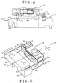
- Fig. 4 is a side elevation, when taken from the side of a spindle motor 180, of the pickup device 200. The construction of the pickup device 200 will be described in the following with reference to Figs. 2 to 4.
- the pickup device 200 of the invention is constructed to include: an actuator unit 140 connecting a moving unit 130, as having a printed circuit board A coil 50 and a printed circuit board B coil 60 fixed on the two side faces of a lens holder 30 holding an objective lens 37, to an actuator base 40 by four wire-form elastic members 74, 94, 80 and 104 and supporting the moving unit 130 movably; a suspension base 150 equipped with a pair of yokes 152, which fix a pair of multi-pole magnetized magnets 151 composed of an I-shaped N-pole and a U-shaped S-pole arranged on the two side faces of the moving unit 130 to confront each other through a predetermined magnetic space, and having upright portions 153 arranged to confront each other while enclosing the side face of the moving unit 130 in the tracking direction (as indicated by arrow T); and a pickup body 170 die-cast of aluminum for housing optical parts including a light source, a collimator lens and a beam splitter, although not shown, and having a semicircular rece
- the actuator unit 140 is fixed on the actuator base 40 by inserting a not-shown screw with a spring and a fixing screw into two mounting holes 41 and 42 of the actuator base 40.
- the actuator unit 140 is fixed at an adjusted position in the direction, as indicated by arrow R1 in Fig. 2, by a V-shaped groove formed in the bottom face of the actuator base 40 and by an M-shaped projecting plate 155 formed on the suspension base 150.
- the actuator unit 140 is fixed by fitting at its one end on a post 173 with a spring, as fixed on a pickup body 175, and by fixing its other end by a fixing screw 174.
- the suspension base 150 is fixed at an arranged position in the direction of arrow R2 by projections 158, as formed on right and left upright portions 153a and 153b, and M-shaped holding portions 172 of the pickup body 170.
- the pickup device 200 of the embodiment of the invention is enabled to approach the side of the spindle motor 180 by forming the semicircular recess 171 in the side face of the pickup body 170 in the inner peripheral direction Si.
- the distance Ti from the wire-form elastic members 80 and 104 supporting the moving unit 130 to the optical center (i.e., Oc containing the optical axis of the objective lens 37 and perpendicular to the tracking direction) of the objective lens 37 is made shorter than the distance To from the wire-form elastic members 74 and 94 to the optical center line Oc of the objective lens 37, as shown in Fig. 3.
- the wire-form elastic members 74 and 94 and the wire-form elastic members 80 and 104 supporting the moving unit 130 are positioned asymmetric with respect to the optical center line Oc of the objective lens 37 so that the objective lens 37 of the pickup device 200 can be brought closer to the inner circumferential side of the optical disk.
- the pickup device 200 of the embodiment of the invention is constructed to come closer to the spindle motor 180 and the inner circumferential side of the optical disk by forming the semicircular recess 171 in the pickup body 170 and by fixing the four wire-form elastic members 74, 94, 80 and 104 for supporting the moving unit 130, asymmetric with respect to the optical center line Oc of the objective lens 37.
- the moving unit 130 thus constructed establishes the angular moment, but the pickup device 200 of the embodiment of the invention is made small and light without establishing the angular moment by devising the structure of the actuator unit 140.
- the structure of the actuator unit 140 With reference to Fig. 5, therefore, here will be described not only the entire structure of the actuator unit 140 to be used in the pickup device 200 according to the embodiment of the invention but also the structures of the individual components of the actuator unit 140.
- the actuator unit 140 is constructed, as shown in Fig. 5 such that the printed circuit board A coil 50 is fixed on the front side face (as indicated by arrow Sf) of the lens holder 30 having the objective lens 37 held therein and such that the moving unit 130 having the printed circuit board B coil 60 fixed on the back side face (as indicated by arrow Sb) of the lens holder 30 is movably supported by the four wire-form elastic members 74, 80, 94 and 104 fixed on the actuator base 40.
- These four wire-form elastic members 74, 80, 94 and 104 constructing the actuator unit 140 are integrally molded by the inserting molding method when the lens holder 30 and the actuator base 40 are molded out of a resin.
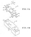
- Fig. 6A is a perspective view of the lens holder 30, and Fig. 6B is a perspective view of the actuator base 40.
- the lens holder 30 is a generally rectangular member molded out of a resin and having a hollow structure and is provided at a central portion of a top face 31 with an aperture 32 for the objective lens 37.
- the lens holder 30 is constructed to include: a pair of fixing arms 34a and 34b or elastic member fixing portions located on the back side Sb of the lens holder 30 and extending horizontally in the inner peripheral direction Si from the top face 31 and a bottom face 33 positioned at a spacing from the top face 31 in the focusing direction (as indicated by arrow F); a pair of fixing arms 35a and 35b or other elastic member fixing portions located on the back side Sb of the lens holder 30 and extending horizontally in the outer peripheral direction So from the top face 31 and the bottom face 33; and a pair of projecting portions 36a and 36b or terminal fixing portions located on the front side Sf of the lens holder 30 and extending horizontally in the outer peripheral direction So from the top face 31 and the bottom face 33.
- the actuator base 40 is a generally rectangular member molded out of a resin and including: the two mounting holes 41 and 42 formed for fixing it on the suspension base 150; grooves 43a and 43b molded integrally with the four wire-form elastic members 74, 80, 94 and 104 on the two longitudinal sides; and a V-shaped groove 44 formed in the bottom portion for adjusting the position.
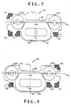
- the printed circuit board A coil 50 shown in Fig. 7 is fixed on the front side face Sf of the lens holder 30 so that coils and terminals to be described are formed on the side of the lens holder 30.
- a substrate 51 is shown in a perspective state.
- the coils and the terminals are formed on the same side on the back of the drawing.
- the printed circuit board B coil 60 is fixed on the back side face Sb of the lens holder 30 so that the coils and the terminals are shown in the state where they are formed on the same side of this side of the drawing.
- the printed circuit board A coil 50 is formed by plating the flat substrate 51 with copper to form the coils, the wires and so on in a pattern, as shown in Fig. 7. There are formed on the same face a tracking A coil 52a, a tracking B coil 52b, a focusing A coil 53, and four terminal parts (i.e., a tracking A input terminal part 54, a tracking A output terminal part 55, a focusing A input terminal part 56 and a focusing A output terminal part 57) made of a copper foil.
- the tracking A coil 52a and the tracking B coil 52b are arranged over the substrate 51 and formed symmetrically with respect to an optical axis La to have the same shape.
- the focusing A coil 53 is located at its center on the optical axis La and is formed below a line of action DL joining the centers of the tracking A coil 52a and the tracking B coil 52b.
- the substrate 51 is cut away at its upper portion to form a notch 58 and is protruded downward to form a bulge 59 so as to bear the later-described counter weight of the moving unit 130.
- the tracking A coil 52a as connected with the tracking A input terminal part 54, is turned counter-clockwise from the outer periphery to the inner periphery and is connected through a through hole and a copper foil, although not shown, with the tracking B coil 52b.
- This tracking B coil 52b is turned clockwise from the inner periphery to the outer periphery and is connected with the tracking A output terminal part 55. Therefore, the tracking A coil 52a and the tracking B coil 52b are connected in series between the tracking A input terminal part 54 and the tracking A output terminal part 55.
- the focusing A coil 53 as connected with the focusing A input terminal part 56, is turned clockwise from the outer periphery to the inner periphery and is connected with the through hole and the copper foil with the focusing A output terminal part 57.
- the printed circuit board B coil 60 is formed like the printed circuit board A coil 50 by plating the flat substrate 51 with copper to form the coils, the wires and so on in a pattern.
- a tracking C coil 62a a tracking D coil 62b, a focusing B coil 63, and four terminal parts (i.e., a tracking B input terminal part 64, a tracking B output terminal part 66, a focusing B input terminal part 66 and a focusing b output terminal part 67) made of a copper foil.
- the tracking C coil 62a and the tracking D coil 62b are arranged over the substrate 61 and formed symmetrically with respect to an optical axis La to have the same shape.
- the focusing B coil 63 is located at its center on the optical axis La and is formed below a line of action DL joining the centers of the tracking C coil 62a and the tracking D coil 62b.
- the substrate 61 is cut away at its upper portion to form a notch 68 and is protruded downward to form a bulge 69.
- the tracking C coil 62a as connected with the tracking B input terminal part 64, is turned clockwise from the outer periphery to the inner periphery and is connected through a through hole and a copper foil, although not shown, with the tracking D coil 62b.
- This tracking D coil 62b is turned counter-clockwise from the inner periphery to the outer periphery and is connected with the tracking B output terminal part 65. Therefore, the tracking C coil 62a and the tracking D coil 62b are connected in series between the tracking B input terminal part 64 and the tracking B output terminal part 65.
- the focusing B coil 63 as connected with the focusing B input terminal part 66, is turned clockwise from the outer periphery to the inner periphery and is connected with the through hole and the copper foil with the focusing B output terminal part 67.
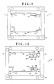
- Fig. 9 is a top plan view of an upper suspension frame 70 which is formed to have the two wire-form elastic members 74 and 80 and the individual connecting parts by punching out the unnecessary portions from a flat metal plate by press work.
- Fig. 10 is a top plan view of an upper suspension frame 90 which is formed to have the two wire-form elastic members 94 and 104 and the individual connecting parts by punching out the unnecessary portions from a flat metal plate by press work.
- the upper suspension frame 70 is arranged on the side of the top face 31 of the lens holder 30, when it is molded integrally with the lens holder 30, and bears a tracking input terminal 72 and a tracking output terminal 78, as will be described.
- the lower suspension frame 90 is arranged on the side of the bottom face 33 of the lens holder 30, when it is molded integrally with the lens holder 30, and bears a focusing input terminal 92 and a focusing output terminal 102, as will be described.
- the upper suspension frame 70 and the lower suspension frame 90 are given the function of a suspension and a wiring function to feed the drive currents to the printed circuit board coils 50 and 60 so that they are formed of metal sheets 71 and 91 having an elastic force and an excellent conductivity and made of a thin sheet (e.g., about 0.1 mm) of titanium-copper, phosphor bronze or beryllium-copper.
- These metal plates 71 and 91 are made of a long hoop material and are formed by punching work using a die such that the four wire-form elastic members 74, 80, 94 and 104 and the individual connecting parts are connected to a frame member 77 by a plurality of holding members 76.
- These metal plates 71 and 91 are provided in plurality at a predetermined pitch while considering the productivity.
- the tracking input terminal 72, as insert-molded in the actuator base 40, and a tracking A input connecting part 73, as insert-molded in the lens holder 30, are jointed by the wire-form elastic member (or the outer periphery A wire) 74 and an A coupling member 75 and are held on the frame member 77 by the holding member 76.
- the tracking output terminal 78, as insert-molded in the upper suspension frame 70, and a tracking B output connecting part 79, as insert-molded in the lens holder 30, are jointed by the wire-form elastic member (or the inner periphery A wire) 80 and are held on the frame member 77 by the holding member 76.
- the frame member 77 of the upper suspension frame 70 there are formed a plurality of fixing holes 81 for fixing the upper suspension frame 70 precisely at a predetermined position of a mold to be described.
- the focusing input terminal 92, as insert-molded in the actuator base 40, and a focusing A input connecting part 93, as insert-molded in the lens holder 30, are jointed by the wire-form elastic member (or the outer periphery B wire) 94 and a B coupling member 95 and are held on a frame member 97 by a holding member 96.
- the focusing output terminal 102, as insert-molded in the actuator base 40, and a focusing B output connecting part 103, as insert-molded in the lens holder 30, are jointed by the wire-form elastic member (or the inner periphery B wire) 104 and are held on the frame member 97 by the holding member 96.
- a tracking A output connecting part 106 is jointed to the inner periphery B wire 104 by an E coupling member 105
- a tracking B input connecting part 108 is jointed to the tracking A output connecting part 106 by an F coupling member 107.
- the frame member 97 of the lower suspension frame 90 there are formed a plurality of fixing holes 109 as in the upper suspension frame 70.
- the upper suspension frame 70 and the lower suspension frame 90 are made of the metal plates 71 and 91 having an equal thickness (H), and the outer periphery A wire 74 and the outer periphery B wire 94 of the lower suspension frame 90 are formed at the same position with respect to the frame members 77 and 97 to have an equal width (Wo).
- the inner periphery B wire 80 of the upper suspension frame 70 and the inner periphery B wire 104 of the lower suspension frame 90 are formed at the same position with respect to the frame members 77 and 97 to have an equal width (Wi)l.
- the width (Wo) of the outer periphery A wire 74 of the upper suspension frame 70 and the outer periphery B wire 94 of the lower suspension frame 90 is made smaller than the width (Wi) of the inner periphery B wire 80 of the upper suspension frame 70 and the inner periphery B wire 104 of the lower suspension frame 90.
- Fig. 11 is a structural diagram of an essential portion of the mold and shows only the portion of the lens holder 30, but the detail is omitted.
- the mold is composed of four parts of a lower stationary part 110, a pair of left and right movable parts 111 and 112, and an upper movable part 113, and is provided with a sprue 114, through which the resin is poured into the upper movable part 113.
- the lower suspension frame 90 is fixed in the mold.
- the lower suspension frame 90 is fixed at a predetermined position in the lower stationary part 110 of the mold.
- This lower stationary part 110 is provided with the not-shown positioning pins so that the lower suspension frame 90 is precisely positioned with respect to the lower stationary part 110 by bringing the fixing holes 109 of the lower suspension frame 90 onto those positioning pins.
- the left movable part 111 and the right movable part are placed at a predetermined position of the lower stationary part 110 while clamping the lower suspension frame 90.
- the upper suspension frame 70 is fixed at predetermined positions of the left movable part 111 and the right movable part 112.
- the left movable part 111 or the right movable part 112 is provided with the not-shown positioning pins so that the upper suspension frame 70 is precisely positioned with respect to the left movable part 111 and the right movable part 112 by bringing the fixing holes 81 of the upper suspension frame 70 onto those positioning pines.
- the upper movable part 113 is placed on the left movable part 111 and the right movable part 113 while clamping the upper suspension frame 70.
- the upper suspension frame 70 and the lower suspension frame 90 are fitted in the mold to form a resin space 115 for the lens holder 30 while enclosing the upper suspension frame 70 and the lower suspension frame 90.
- the resin space 115 is charged with the resin through the sprue 114.
- the mold is disassembled in the procedure, as reversed from that of the mold assembling procedure thus far described.
- the left movable part 111 and the right movable part 112 are taken out by sliding them to the left and right.
- These left and right movable parts 111 and 112 are once fixed while being slid in the left and right directions, and are taken out after a damping material of an ultraviolet-set resin is applied to the grooves 43a and 43b formed in the two side faces of the actuator base 40.
- suspension unit 120 which are formed in plurality in a ladder shape and in which the lens holder 30 and the actuator base 40 are molded integrally with the upper suspension frame 70 and the lower suspension frame 90.
- Fig. 13 is a perspective top plan view showing the state in which the lens holder 30 and the actuator base 40 are molded integrally with the upper suspension frame 70.
- the lens holder 30 is shown to include the paired left and right fixing arms 34a and 35a formed on the side of the top face 31, and the projecting portions 36a.
- the outer periphery A wire 74, the inner periphery A wire 80 and the individual coupling members are fixed such that they are partially enveloped by the resin but such that the leading end portions of the individual connecting parts are exposed from the resin.
- Fig. 14 is a perspective top plan view showing the state in which the lens holder 30 and the actuator base 40 are molded integrally with the lower suspension frame 90.
- the lens holder 30 is shown to include the paired left and right fixing arms 34b and 35b formed on the side of the bottom face 33, and the projecting portions 36b.
- the outer periphery B wire 94, the inner periphery B wire 104 and the individual coupling members are fixed such that they are partially enveloped by the resin but such that the leading end portions of the individual connecting parts are exposed from the resin.
- the upper suspension frame 70 and the lower suspension frame 90 are cut away, by removing the portions indicated by the frames of the dotted lines, from the frame members 77 and 97 to form the suspension unit 120, such that the lens holder 30 and the actuator base 40 are jointed to the four wire-form elastic members 74, 80, 94 and 104.
- the upper suspension frame 70 is cleared of the two dotted-line frames a and b , as shown in Fig. 13, by a laser-cutting or punching treatment.
- the outer periphery A wire 74 as connected to the tracking input terminal 72 molded integrally with the actuator base 40 and cut away from the frame member 77, is cut away from the frame member 77 and is fixed on the fixing arm 35a of the lens holder 30, and the tracking A input connecting part 73, as jointed by the A coupling member 75, is fixed on the projecting portion 36a while being exposed to the front side face of the lens holder 30.
- the inner periphery A wire 80 as connected to the tracking output terminal 76 molded integrally with the actuator base 40 and cut away from the frame member 77, is cut away from the frame member 77 and is fixed on the fixing arm 34a of the lens holder 30, and the tracking B output connecting part 79, as connected with the inner periphery A wire 80, is fixed while being exposed to the back side face of the lens holder 30.
- the focusing B input connecting part 99 as cut away from the outer periphery B wire 94, is fixed while being exposed to the back side face of the lens holder 30, and the focusing B output connecting part 101, as jointed to the focusing B input connecting part 99 at the D coupling member 100, is fixed while being exposed to the front side face of the lens holder 30.
- the inner periphery B wire 104 as connected with the focusing output terminal 102 molded integrally with the actuator base 40 and cut away from the frame member 97, is cut away from the frame member 97 and is fixed on the fixing arm 34b of the lens holder 30, and the focusing B output connecting part 103, as connected with the inner periphery B wire 104, is fixed while being exposed to the back side face of the lens holder 30.
- the tracking B input connecting part 108 as cut away from the frame member 97, is fixed while being exposed to the back side face of the lens holder 30, and the tracking A output connecting part 106, as connected with the tracking B input connecting part 108 at the F coupling member 107, is fixed while being exposed to the front side face of the lens holder 30.
- FIG. 15 shows the state in which the printed circuit board A coil 50 and the printed circuit board B coil 60 are arranged at positions apart from the two side faces of the lens holder 30 and in which the individual connecting parts molded integrally with the lens holder 30 are schematically extended (as indicated by dotted lines).
- the individual connecting parts of the lens holder 30 having the objective lens 37 held therein are formed in positional relations to contact with the individual terminals formed at the printed circuit board A coil 50 and the printed circuit board B coil 60 being fixed at predetermined positions of the lens holder 30.
- the four terminal portions (i.e., the tracking A input terminal part 54, the tracking A output terminal part 55, the focusing A input terminal part 56 and the focusing A output terminal part 57) of the printed circuit board A coil 50 are in the positional relations to abut against the end faces of the four connecting parts (i.e., the tracking A input connecting part 73, the focusing A input connecting part 93, the focusing B output connecting part 101) and the tracking A output connecting part 106) which are formed while being fixed at the predetermined positions of the front side face of the lens holder 30 and exposed to the front side face of the lens holder 30.
- the four terminal portions (i.e., the tracking b input terminal part 64, the tracking B output terminal part 65, the focusing B input terminal part 66 and the focusing B output terminal part 67) of the printed circuit board B coil 60 are in the positional relations to abut against the end faces of the four connecting parts (i.e., the tracking B input connecting part 79, the focusing B input connecting part 99, the focusing B output connecting part 103 and the tracking B input connecting part 108) which are formed while being exposed to the back side face of the lens holder 30. Therefore, these are soldered to form the actuator unit 140.
- the outer periphery A wire 74 as connected with the tracking input terminal 72, is connected through the A coupling member 75 with the tracking A input terminal part 54, and the tracking A input terminal part 54 is soldered to the tracking A input terminal part 54 of the printed circuit board A coil 50.
- the tracking A output terminal part 55 of the printed circuit board A coil 50 is soldered to the tracking A output connecting part 106 of the lens holder 30, and the tracking B input connecting part 108 of the lens holder 30, as jointed to the tracking A output connecting part 106 at the F coupling member 107, is soldered to the tracking B input terminal part 64 of the printed circuit board B coil 60.
- the inner periphery A wire 80 as connected with the tracking output terminal 78, is connected with the tracking B output connecting part 79, and the tracking B output connecting part 79 is soldered to the tracking B output terminal part 65 of the printed circuit board B coil 60.
- the tracking A coil 52a and the tracking B coil 52b of the printed circuit board A coil 50 are connected in series between the tracking A input terminal part 54 and the tracking A output terminal part 55, and the tracking C coil 62a and the tracking D coil 62b of the printed circuit board B coil 60 are connected in series between the tracking B input terminal part 64 and the tracking B output terminal part 65. Therefore, the four tracking coils 52a, 52b, 62a and 62b are connected in series between the tracking input terminal 72 and the tracking output terminal 78.
- the outer periphery B wire 94 as connected with the focusing input terminal 92, is connected through the B coupling member 95 with the focusing A input terminal part 93, and the focusing A input terminal part 93 is soldered to the focusing A input terminal part 56 of the printed circuit board A coil 50.
- the focusing A output terminal part 57 of the printed circuit board A coil 50 is soldered to the focusing A output connecting part 101 of the lens holder 30, and the focusing B input connecting part 99 of the lens holder 30, as connected with the tracking A output connecting part 101 at the C coupling member 100, is soldered to the focusing B input terminal part 66 of the printed circuit board B coil 60.
- the inner periphery B wire 104 as connected with the focusing output terminal 102, is connected with the focusing B output connecting part 103, and the focusing B output connecting part 103 is soldered to the focusing B output terminal part 67 of the printed circuit board B coil 60.
- the focusing A coil 53 of the printed circuit board A coil 50 is connected between the focusing A input terminal part 56 and the focusing A output terminal part 57
- the focusing B coil 63 of the printed circuit board B coil 60 is connected between the focusing B input terminal part 66 and the focusing B output terminal part 67. Therefore, the focusing A coil 53 and the focusing B coil 63 are connected in series between the focusing input terminal part 94 and the focusing output terminal part 104.
- the actuator unit 140 to be used in the pickup device 200 thus far described according to the embodiment of the invention need not be connected with the outside by using any wiring material, because the four wire-form elastic members 74, 80, 94 and 104 are molded integrally with the lens holder 30 and the actuator base 40 and because the individual coupling members for connecting the printed circuit board A coil 50 and the printed circuit board B coil 60 are integrally molded. Therefore, the working steps are simplified to provide the highly reliable actuator unit 140.
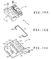
- Fig. 16A is a perspective view of the actuator unit 140
- Fig. 16B is a perspective view of a stopper member 157
- Fig. 16C is a perspective view of the suspension base 150.
- the actuator unit 140 is fixed after the V-shaped grooves 44 of the actuator base 40 were placed on the two M-shaped projecting plates 155 of the suspension base 150 and positionally adjusted by a screw 45 with a spring and a fixing screw 46.
- the moving unit 130 is supported movably while forming a predetermined magnetic space with respect to the paired magnets 151.
- the stopper members 157 are inserted into insert holes 154 of the paired upright portions 153 formed to enclose the moving unit 130.
- the stopper member 157 is the wire-form member which is folded generally in a C-shape as a whole, as shown in Fig. 16B, and is provided at the leading ends of the C-shaped body with restricting portions 158a and 158b projecting to the inner sides of the upright portions 153, i.e., on the side of the moving unit 130.
- the stopper member 157 is made of an elastic member having a spring effect so that the leading ends of the two restricting portions 158a and 158b may be inserted from the outer sides of the upright portions 153 when the stopper member 157 is to be inserted into the insert holes 154 of the upright portions 153.
- the actuator unit 140 as placed on the suspension base 150, is restricted in the moving range of the moving unit 130 in the tracking direction by the paired upright portions 153 disposed to enclose the moving unit 130 and in the moving range of the moving unit 130 in the focusing direction by the stopper member 157.
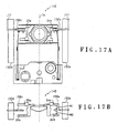
- Fig. 17A is a top plan view showing the positional relation between the upright portions 153 and the stopper member 157 of the suspension base 150
- Fig. 17B is a side elevation showing the positional relations among the lens holder 30 holding the objective lens 37, the upright portions 153 and the stopper member 157.
- one restricting portion 158a of the stopper member 157 is arranged at the central portions of the fixing arms 34a and 34b which are spaced in the focusing direction in the lens holder 30, and the other restricting portion 158b of the stopper member 157 is arranged at the central portion of the other fixing arms 35a and 35b which are spaced in the focusing direction in the lens holder 30.
- the moving unit 130 is driven in the upward focusing direction, therefore, it is restricted in its moving range by the distance M2 in which the left and right fixing arms 34b and 35b formed on the side of the bottom face 33 of the lens holder 30 come into abutment against the restricting portions 158a and 158b.
- the moving unit 130 is driven in the downward focusing direction, on the other hand, it is restricted in its moving range by the distance M1 in which the left and right fixing arms 34a and 34b formed on the side of the top face 31 of the lens holder 30 come into abutment against the restricting portions 158a and 158b.
- the fixing arms 35a and 35b or the stationary portions of the elastic members are utilized as the mechanism for restricting the moving ranges of in the focusing directions so that the cost is lowered.
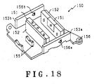
- the insert holes 154 as formed in the upright portions 153, may be exemplified by a pair of insert holes 156a and 156b having a plurality of insert positions, as shown in Fig. 18.
- the upward moving range and the downward moving range of the moving unit 130 can be specified differently from each other to raise the versatility of the suspension base 150.
- the actuator unit 140 is fixed on the suspension base 150, as has been described hereinbefore, the stopper member 157 is then inserted into the insert holes 154 of the upright portions 153. Moreover, the suspension base 150 is fixed on the pickup body 170 to complete the pickup device 200 according to the embodiment of the invention.
- the moving unit 130 constructing the pickup device 200 of the embodiment of the invention is restricted not only in the moving range in the tracking direction by the upright portions 153 of the suspension base 150 but also in the moving range in the focusing direction by the stopper member 157. Therefore, the pickup device 200 according to the embodiment of the invention does not need any actuator cover so that it can be made small and light.
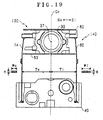
- Figs. 19 and 20 here will be described the constructions of the four wire-form elastic members 74, 80, 94 and 104 supporting the moving unit 130and their actions to prevent the rolling of the moving unit 130.
- This moving unit 130 is actually supported by the four wire-form elastic members 74, 80, 94 and 104 but is shown to use only the outer periphery A wire 74 and the inner periphery A wire 80 so as to avoid complexity of the description. No difference in the actions will arise.
- Fig. 19 is a top plan view of the actuator unit 140
- Fig. 20 is a schematic diagram for explaining the angular moment of the moving unit 130.
- the distance Ti from the inner periphery A wire 80 for supporting the moving unit 130 to the optical center line Oc of the objective lens 37 is made smaller than the distance To from the outer periphery A wire 74 to the optical center line Oc of the objective lens 37, as has been described hereinbefore. Accordingly, the inner periphery A wire 80 and the outer periphery A wire 74 are formed to have the same thickness H, but the width Wi of the inner periphery A wire 80 is made larger than the thickness Wo of the outer periphery A wire 74 (i.e., Wi > Wo).
- the inner periphery A wire 80 has a spring constant Ki, as expressed by the following Formula (1): Ki ⁇ Ti3H
- the outer periphery A wire 74 has a spring constant Ko, as expressed by the following Formula (2): Ko ⁇ To3H
- the spring constant Ki of the inner periphery A wire 80 is larger than the spring constant Ko of the outer periphery A wire 74 (i.e., Ki > Ko).
- the restoring force Fi of the inner periphery A wire 80 is higher than the restoring force Fo of the outer periphery A wire 74 (i.e. , Fi > Fo).
- the angular moment of the moving unit 130 is determined by the product of the distance from a center of gravity Gt of the moving unit 130 (whereas the point of action of the focusing drive force and the center of gravity of the moving unit 130 are aligned with the optical axis La) to the spring (e.g., the inner periphery A wire 80 and the outer periphery A wire 74) and the restoring force of the position where the spring (e.g., the inner periphery A wire 80 and the outer periphery A wire 74) are fixed.
- the spring e.g., the inner periphery A wire 80 and the outer periphery A wire 74
- the pickup device 200 is constructed such that the distance Ti from the inner periphery A wires 80 to 104 supporting the moving unit 130 to the optical center line Oc of the objective lens 37 is made smaller than the distance To from the outer periphery A wires 74 and 94 to the optical center line Oc of the objective lens 37, and such that the width Wi of the inner periphery A wires 80 and 104 is made larger than the thickness Wo of the outer periphery A wires 74 and 94.
- the inner periphery side of the actuator unit 140 i.e., the side of the spindle motor 180 can be made smaller than the outer periphery side so that the objective lens can be brought closer to the inner periphery side of the optical disk.
- the spring constants of the wire-form elastic members 74, 80, 94 and 104 can also be set different not only between the inner periphery side and the outer periphery side but also between the wire-form elastic members 74 and 80 on the upper side of the focusing direction and the wire-form elastic members 94 and 104 on the lower side.
- the distance Ti from the center of gravity Gt of the moving unit 130 to the wire-form elastic members 74 and 80 on the upper side and the distance To to the wire-form elastic members 94 and 104 on the lower side are made different, as shown in Fig. 21.
- the spring constants of the wire-form elastic members 74 and 80 on the upper side and the wire-form elastic members 94 and 104 on the lower side may be properly set to satisfy the aforementioned Formula (4) so that the generation of the angular moment by the restoring force of the spring may be suppressed.
- the setting of the spring constants need not always satisfy the aforementioned Formula (4). It is contributory to the suppression of the rolling to set the spring constants different so that the angular moment to be applied to the moving unit is lower than that of the case in which all the spring constants are equal.
- Figs. 22 to 25 show only the printed circuit board A coil 50.
- Fig. 22 is a diagram showing the center of gravity when the objective lens 37 is held in the lens holder 30
- Fig. 23 is a diagram showing the center of gravity of the printed circuit board A coil 50
- Fig. 24 is a diagram showing the center of gravity of the moving unit 130.
- Fig. 25 shows an example of the case in which the focusing A coil 53 is disposed at a lower position.
- the lens holder 30 is a generally rectangular member molded out of a resin and having a hollow structure, as has been described hereinbefore, and has the top face 31 so that its center of gravity is located at the position Gb closer to the top face 31 from the center of the lens holder 30, as shown in Fig. 22. With the objective lens 37 being held in this lens holder 30, the center of gravity of the lens holder 30 moves toward the top face 31 to the position, as indicated by Gn.
- the printed circuit board A coil 50 has the recessed notch 58 formed in the upper portion of the substrate 51 in the region between the tracking A coil 52a and the tracking B coil 52b, as shown in Fig. 23, and has the bulge 59 on the bottom portion of the substrate 51.
- the printed circuit board A coil 50 has the tracking a coil 52a and the tracking B coil 52b formed symmetrically with respect to the optical axis La. Therefore, the center of gravity of the tracking A coil 52a and the tracking B coil 52b is located at the intersection, as indicated by Gt, between the line of action DL of the tracking drive force joining the center points of the two tracking coils 52a and 52b and the optical axis La.
- the center of gravity of the focusing A coil 53 is located at the intersection, as indicated by Gf, with the optical axis La at the center of the focusing A coil 53. From the discussion thus far made, the center of gravity of the printed circuit board A coil 50 is located at a position Gp below the center of gravity Gt of the two tracking coils 52a and 52b and over the center of gravity Gf of the focusing A coil 53.
- Fig. 25 shows the state in which the printed circuit board A coil 50 is fixed on the lens holder 30. If the printed circuit board A coil 50 is fixed at a position to align the top face 31 of the lens holder 30 and the top face of the substrate 51, its bulge 59 is protruded downward from the bottom face 33 of the lens holder 30.
- the moving unit 130 has its center of gravity Gm located on the optical axis La of the objective lens 37 and on the line of action DL of the tracking drive force.
- the center of gravity of the moving unit 130 can be set at the intersection between the line of action DL of the tracking drive force and the optical axis La to establish no angular moment when the moving unit 130 is driven in the tracking direction.
- the weight of the focusing coil 53 can be used as the counter weight so that adverse affects by the angular moment can be more avoided without increasing the weight of the moving unit 130 than the those of the case in which the dedicated counter weight is used.
- the notch 58 formed over the substrate 51 can reduce the center of gravity of the printed circuit board A coil 50 and can enlarge the distance, i.e., N2 between the line of action DL of the two tracking coils 52a and 52b and the center of gravity Gp of the printed circuit board A coil 50.
- the weight effect as the counter weight is enhanced.
- the notch 58 in the substrate 51 more specifically, the weight as the counter weight can be substantially enlarged without increasing the total weight of the moving unit 130. As a result, the allowance and the versatility are improved for the weight of the objective lens 37.
- the printed circuit board A coil 50 may be constructed such that the focusing a coil 53 is at a lower position, as shown in Fig. 25.
- the center of gravity Gf of the focusing A coil 53 is located at a lower position than that of the example shown in fig. 23, so that the center of gravity Gp of the printed circuit board A coil 50 is shifted downward.
- the weight of the substrate 51 is made larger than that of the example shown in Fig. 23, and the bulge 59 of the substrate 51 is enlarged to restrict the moving range of the moving unit 130 in the downward focusing direction. Therefore, the shape of the printed circuit board A coil 50 is set according to the position of the center of gravity of the lens holder 30 holding the objective lens 37.
- Fig. 26 is an explanatory diagram showing the relation between the relative positions of the printed circuit board A coil 50 and the magnet 151 when the moving unit 130 is in the normal position.
- the magnet 151 is a multi-pole magnetizable magnet which is magnetized with an N pole, for example, in the generally square shape, and with a generally U-shaped S pole enclosing the N pole from the three sides.
- the region magnetized with the N pole generates the magnetic flux which is directed normal to the surface of the drawing from the back to the front, and the region magnetized with the S pole generates the magnetic flux which is directed normal to the drawing surface from the front to the back.
- the individual coils, as formed in the printed circuit board A coil 50 are arranged to have their center positioned on the boundary line between the N pole and the S pole of the magnet 151.
- the tracking drive current is fed between the tracking inner periphery 54 and the tracking output terminal 55 so that the electric current flows in the direction of arrows through the tracking A coil 52a and the tracking B coil 52b, the leftward tracking drive force is generated, as indicated by arrow T. If a reverse drive current is fed, on the other hand, the rightward tracking drive force is generated, as reversed from the arrow T.
- the focusing drive current is fed to the focusing input terminal part 56 and the focusing output terminal part 57 so that the electric current in the shown direction flows through the focusing coil 53, an upward drive force is generated, as indicated by arrow F. If a reverse drive current is fed, the downward focusing drive force is generated, as reversed from the arrow F.
- the lens holder is molded out of a resin integrally with the connection wires connecting the drive coils electrically. It is, therefore, possible to provide a highly reliable lens drive device which can avoid the disadvantage such as the breakage of the connection wires and can simplify the assembling works.
Landscapes
- Physics & Mathematics (AREA)
- Optics & Photonics (AREA)
- Optical Recording Or Reproduction (AREA)
- Lens Barrels (AREA)
- Optical Head (AREA)
Abstract
Description
Claims (7)
- A lens drive device comprising:a lens holder to which an objective lens and a plurality of drive coils are fixed, anda plurality of wire-form elastic members made of a metal, for supporting said lens holder, in which said drive coils are energized through said wire-form elastic members,wherein said lens holder is molded out of a resin integrally with connection wires for connecting said drive coils electrically.
- A lens drive device according to Claim 1,
wherein said lens holder is molded integrally with said connection wires while containing at least portions of said connection wires and while being exposed at its two ends, so that said exposed portions may be connection terminals to said drive coils. - A lens drive device in which a lens holder and a suspension base are integrally molded out of a resin on the two end sides of a plurality of wire-form elastic members made of a metal, in which an objective lens and a plurality of drive coils are fixed on said molded lens holder, and in which said drive coils are energized through said wire-form elastic members,wherein said wire-form elastic members are provided at their one-side ends with connection terminals which are partially exposed from said lens holder and connected with said drive coils, andwherein connection wires for connecting said drive coils are integrally molded while being contained in said lens holder.
- A lens drive device according to Claim 3,wherein said connection wires are provided at their two ends with connection terminals to be connected with said drive coils, andwherein said connection terminals are exposed from said lens holder.
- A suspension unit for a lens drive device, comprising a lens holder and a suspension base,wherein said lens holder and said suspension base are integrally molded out of a resin on the two end sides of a plurality of wire-form elastic members made of a metal, andwherein connection wires for electrically connecting said drive coils to be fixed on said lens holder are integrally molded while being contained in said lens holder.
- A method for manufacturing a lens drive device, in which a lens holder for fixing an objective lens and a plurality of drive coils to be electrically connected through connection wires thereon and a suspension base are jointed through a plurality of wire-form elastic members made of a metal, to support said lens holder movably and to energize said drive coils through said wire-form elastic members, comprising:a first step of positioning said wire-form elastic members and said connection wires in predetermined positional relations;a second step of molding a lens holder of a resin integrally with said wire-form elastic members and said connection wires on one-end side of said wire-form elastic members and a suspension base of a resin integrally with said wire-form elastic members at the other end of said wire-form elastic members; anda third step of fixing said objective lens and said drive coils on said lens holder and connecting said wire-form elastic members made and the terminals of said connecting parts with the terminals of said drive coils.
- A lens drive device manufacturing method according to Claim 6,wherein said wire-form elastic members and said connection wires are jointed and positioned relative to each other through joint parts at said first step and said second step,further comprising a step of cutting said joint parts between said second step and said third step.
Applications Claiming Priority (2)
| Application Number | Priority Date | Filing Date | Title |
|---|---|---|---|
| JP2000032506A JP2001229555A (en) | 2000-02-09 | 2000-02-09 | Lens driving device, suspension unit for lens driving device and method for manufacturing lens driving device |
| JP2000032506 | 2000-02-09 |
Publications (3)
| Publication Number | Publication Date |
|---|---|
| EP1124226A2 true EP1124226A2 (en) | 2001-08-16 |
| EP1124226A3 EP1124226A3 (en) | 2003-04-23 |
| EP1124226B1 EP1124226B1 (en) | 2007-12-26 |
Family
ID=18557100
Family Applications (1)
| Application Number | Title | Priority Date | Filing Date |
|---|---|---|---|
| EP01301064A Expired - Lifetime EP1124226B1 (en) | 2000-02-09 | 2001-02-07 | Lens drive device and method for manufacturing the same |
Country Status (4)
| Country | Link |
|---|---|
| US (1) | US7219358B2 (en) |
| EP (1) | EP1124226B1 (en) |
| JP (1) | JP2001229555A (en) |
| DE (1) | DE60132036T2 (en) |
Cited By (2)
| Publication number | Priority date | Publication date | Assignee | Title |
|---|---|---|---|---|
| WO2005052931A3 (en) * | 2003-11-25 | 2005-07-28 | Koninkl Philips Electronics Nv | Method of manufacturing at least one actuator, as well as a lead frame, optical reading and/or writing head, and an optical reading and/or writing device |
| EP1903567A3 (en) * | 2006-09-20 | 2008-12-31 | Funai Electric Co., Ltd. | Objective lens actuator and optical pickup device |
Families Citing this family (20)
| Publication number | Priority date | Publication date | Assignee | Title |
|---|---|---|---|---|
| US6828890B2 (en) | 2001-09-26 | 2004-12-07 | Engineering Matters, Inc. | High intensity radial field magnetic array and actuator |
| KR100941532B1 (en) * | 2002-03-26 | 2010-02-10 | 파나소닉 주식회사 | Objective lens drive unit, optical head and optical disc unit |
| JP2004005813A (en) | 2002-05-31 | 2004-01-08 | Tdk Corp | Optical head device and optical reproducing device using the same |
| US6876284B2 (en) | 2002-09-26 | 2005-04-05 | Engineering Matters, Inc. | High intensity radial field magnetic array and actuator |
| US7352268B2 (en) * | 2002-09-26 | 2008-04-01 | Engineering Matters, Inc. | High intensity radial field magnetic actuator |
| JP4225931B2 (en) | 2004-02-18 | 2009-02-18 | パイオニア株式会社 | Method for forming pickup actuator and pickup actuator |
| WO2005096288A1 (en) * | 2004-03-30 | 2005-10-13 | Pioneer Corporation | Actuator for pickup, pickup device, recording medium drive device, and method of producing actuator for pickup |
| JPWO2005096287A1 (en) | 2004-03-30 | 2008-07-31 | パイオニア株式会社 | Pickup actuator, pickup device, recording medium drive device, and method for manufacturing pickup actuator |
| JP4448736B2 (en) * | 2004-06-16 | 2010-04-14 | 株式会社日立メディアエレクトロニクス | Optical pickup device and optical disk device using the same |
| JP2007226933A (en) * | 2006-01-25 | 2007-09-06 | Matsushita Electric Ind Co Ltd | Objective lens driving device, method of manufacturing objective lens driving device, optical pickup device, and optical disk device |
| JP5037516B2 (en) * | 2006-10-10 | 2012-09-26 | パナソニック株式会社 | Optical pickup device, optical information device, computer, optical disc player, car navigation system, optical disc recorder, and optical disc server |
| US8085119B2 (en) * | 2007-11-08 | 2011-12-27 | Engineering Matters Inc. | Flexible electromagnetic valve actuator modeling and performance |
| EP2128862A1 (en) | 2008-05-30 | 2009-12-02 | Deutsche Thomson OHG | Flat actuator made from one piece of PCB |
| JP2010176726A (en) * | 2009-01-27 | 2010-08-12 | Pioneer Electronic Corp | Optical pickup device |
| US8387945B2 (en) * | 2009-02-10 | 2013-03-05 | Engineering Matters, Inc. | Method and system for a magnetic actuator |
| JP5094786B2 (en) * | 2009-06-02 | 2012-12-12 | 株式会社日立メディアエレクトロニクス | Objective lens driving device and disk device using the same |
| KR101059599B1 (en) * | 2009-07-01 | 2011-08-25 | 삼성전기주식회사 | Linear vibration motor |
| US8564896B2 (en) | 2010-08-20 | 2013-10-22 | Hong Kong Applied Science And Technology Research Institute Co., Ltd. | Compact imaging device |
| US9663867B2 (en) * | 2013-07-15 | 2017-05-30 | United Technologies Corporation | Plated instrumentation probes and sensors |
| CN119298596A (en) * | 2024-12-09 | 2025-01-10 | 贝隆精密科技股份有限公司 | A voice coil motor bottom shell and production method thereof |
Family Cites Families (6)
| Publication number | Priority date | Publication date | Assignee | Title |
|---|---|---|---|---|
| JPH01235040A (en) * | 1988-03-14 | 1989-09-20 | Asahi Optical Co Ltd | Objective lens supporting device for optical information recording/reproducing device |
| JP2978588B2 (en) * | 1991-05-27 | 1999-11-15 | パイオニア株式会社 | Method for manufacturing lens driving device in optical pickup |
| JPH0863769A (en) * | 1994-06-17 | 1996-03-08 | Sony Corp | Objective lens driving device and manufacturing method thereof |
| JPH09190644A (en) * | 1996-01-09 | 1997-07-22 | Pioneer Electron Corp | Lens driving device and its manufacture |
| JPH09282690A (en) * | 1996-04-10 | 1997-10-31 | Asahi Chem Ind Co Ltd | Movable member for lens driving device |
| JP3819599B2 (en) * | 1998-08-05 | 2006-09-13 | 株式会社東芝 | Method for manufacturing objective lens driving device |
-
2000
- 2000-02-09 JP JP2000032506A patent/JP2001229555A/en active Pending
-
2001
- 2001-02-07 US US09/778,015 patent/US7219358B2/en not_active Expired - Fee Related
- 2001-02-07 EP EP01301064A patent/EP1124226B1/en not_active Expired - Lifetime
- 2001-02-07 DE DE60132036T patent/DE60132036T2/en not_active Expired - Fee Related
Cited By (3)
| Publication number | Priority date | Publication date | Assignee | Title |
|---|---|---|---|---|
| WO2005052931A3 (en) * | 2003-11-25 | 2005-07-28 | Koninkl Philips Electronics Nv | Method of manufacturing at least one actuator, as well as a lead frame, optical reading and/or writing head, and an optical reading and/or writing device |
| CN100411030C (en) * | 2003-11-25 | 2008-08-13 | 皇家飞利浦电子股份有限公司 | Method of manufacturing at least one actuator, as well as lead frame, optical reading and/or writing head, and optical reading and/or writing device |
| EP1903567A3 (en) * | 2006-09-20 | 2008-12-31 | Funai Electric Co., Ltd. | Objective lens actuator and optical pickup device |
Also Published As
| Publication number | Publication date |
|---|---|
| US7219358B2 (en) | 2007-05-15 |
| US20010017490A1 (en) | 2001-08-30 |
| EP1124226A3 (en) | 2003-04-23 |
| EP1124226B1 (en) | 2007-12-26 |
| DE60132036D1 (en) | 2008-02-07 |
| JP2001229555A (en) | 2001-08-24 |
| DE60132036T2 (en) | 2008-12-11 |
Similar Documents
| Publication | Publication Date | Title |
|---|---|---|
| EP1124226B1 (en) | Lens drive device and method for manufacturing the same | |
| JP3888821B2 (en) | Pickup device and manufacturing method thereof | |
| JP3995857B2 (en) | Lens drive device for disc player | |
| US6493158B2 (en) | Lens driving apparatus for optical disc player and printed circuit board coils for lens driving apparatus for disc player | |
| EP0660312B1 (en) | Objective lens drive device and coil bobbin thereof | |
| JP2760307B2 (en) | Objective lens actuator for optical head | |
| EP0650161A1 (en) | Method for producing an objective lens actuator | |
| KR20040110999A (en) | Optical pickup device and manufacturing method thereof | |
| US5850313A (en) | Objective lens driving device and a method for manufacturing the same | |
| JP2003173556A (en) | Optical head device | |
| EP1387354A1 (en) | Objective lens drive device, and optical pickup device using objective lens drive device | |
| JP2002092916A (en) | Objective lens drive device of optical pickup | |
| JP2005251358A (en) | Objective lens driving device, and optical head device provided therewith | |
| JP4686626B2 (en) | Lens drive device | |
| JP3567310B2 (en) | Optical head device | |
| JP2624663B2 (en) | Objective lens drive | |
| JP2000163773A (en) | Optical head actuator | |
| JP2007305300A (en) | Disk player lens driving device and printed-circuit board coil for the disk player lens driving device | |
| JP3570838B2 (en) | Objective lens drive | |
| JP3413736B2 (en) | Two-axis actuator | |
| JPH07176074A (en) | Biaxial actuator manufacturing method | |
| JPH10255292A (en) | Apparatus for driving objective lens of optical pickup and assembling method thereof | |
| JPH08147731A (en) | Biaxial actuator | |
| JPH09251653A (en) | Two-axis actuator | |
| KR20080010607A (en) | Optical recording / reproducing system employing optical pickup device and optical pickup device |
Legal Events
| Date | Code | Title | Description |
|---|---|---|---|
| PUAI | Public reference made under article 153(3) epc to a published international application that has entered the european phase |
Free format text: ORIGINAL CODE: 0009012 |
|
| AK | Designated contracting states |
Kind code of ref document: A2 Designated state(s): AT BE CH CY DE DK ES FI FR GB GR IE IT LI LU MC NL PT SE TR |
|
| AX | Request for extension of the european patent |
Free format text: AL;LT;LV;MK;RO;SI |
|
| PUAL | Search report despatched |
Free format text: ORIGINAL CODE: 0009013 |
|
| AK | Designated contracting states |
Designated state(s): AT BE CH CY DE DK ES FI FR GB GR IE IT LI LU MC NL PT SE TR |
|
| AX | Request for extension of the european patent |
Extension state: AL LT LV MK RO SI |
|
| 17P | Request for examination filed |
Effective date: 20030711 |
|
| AKX | Designation fees paid |
Designated state(s): DE FR GB |
|
| 17Q | First examination report despatched |
Effective date: 20050323 |
|
| GRAP | Despatch of communication of intention to grant a patent |
Free format text: ORIGINAL CODE: EPIDOSNIGR1 |
|
| RTI1 | Title (correction) |
Free format text: LENS DRIVE DEVICE AND METHOD FOR MANUFACTURING THE SAME |
|
| GRAS | Grant fee paid |
Free format text: ORIGINAL CODE: EPIDOSNIGR3 |
|
| GRAA | (expected) grant |
Free format text: ORIGINAL CODE: 0009210 |
|
| AK | Designated contracting states |
Kind code of ref document: B1 Designated state(s): DE FR GB |
|
| REG | Reference to a national code |
Ref country code: GB Ref legal event code: FG4D |
|
| REF | Corresponds to: |
Ref document number: 60132036 Country of ref document: DE Date of ref document: 20080207 Kind code of ref document: P |
|
| PGFP | Annual fee paid to national office [announced via postgrant information from national office to epo] |
Ref country code: GB Payment date: 20080206 Year of fee payment: 8 Ref country code: DE Payment date: 20080131 Year of fee payment: 8 |
|
| REG | Reference to a national code |
Ref country code: GB Ref legal event code: 746 Effective date: 20080611 |
|
| PGFP | Annual fee paid to national office [announced via postgrant information from national office to epo] |
Ref country code: FR Payment date: 20080208 Year of fee payment: 8 |
|
| ET | Fr: translation filed | ||
| PLBE | No opposition filed within time limit |
Free format text: ORIGINAL CODE: 0009261 |
|
| STAA | Information on the status of an ep patent application or granted ep patent |
Free format text: STATUS: NO OPPOSITION FILED WITHIN TIME LIMIT |
|
| 26N | No opposition filed |
Effective date: 20080929 |
|
| GBPC | Gb: european patent ceased through non-payment of renewal fee |
Effective date: 20090207 |
|
| REG | Reference to a national code |
Ref country code: FR Ref legal event code: ST Effective date: 20091030 |
|
| PG25 | Lapsed in a contracting state [announced via postgrant information from national office to epo] |
Ref country code: DE Free format text: LAPSE BECAUSE OF NON-PAYMENT OF DUE FEES Effective date: 20090901 |
|
| PG25 | Lapsed in a contracting state [announced via postgrant information from national office to epo] |
Ref country code: GB Free format text: LAPSE BECAUSE OF NON-PAYMENT OF DUE FEES Effective date: 20090207 Ref country code: FR Free format text: LAPSE BECAUSE OF NON-PAYMENT OF DUE FEES Effective date: 20090302 |