EP1124168A1 - Elektronisches Steuersystem - Google Patents
Elektronisches Steuersystem Download PDFInfo
- Publication number
- EP1124168A1 EP1124168A1 EP01102387A EP01102387A EP1124168A1 EP 1124168 A1 EP1124168 A1 EP 1124168A1 EP 01102387 A EP01102387 A EP 01102387A EP 01102387 A EP01102387 A EP 01102387A EP 1124168 A1 EP1124168 A1 EP 1124168A1
- Authority
- EP
- European Patent Office
- Prior art keywords
- control unit
- signals
- signal
- test
- control system
- Prior art date
- Legal status (The legal status is an assumption and is not a legal conclusion. Google has not performed a legal analysis and makes no representation as to the accuracy of the status listed.)
- Granted
Links
- 230000005540 biological transmission Effects 0.000 claims abstract description 26
- 230000000295 complement effect Effects 0.000 claims description 7
- 238000001514 detection method Methods 0.000 claims description 3
- 230000002596 correlated effect Effects 0.000 claims 1
- 238000000034 method Methods 0.000 claims 1
- 230000006870 function Effects 0.000 description 6
- 238000006243 chemical reaction Methods 0.000 description 1
- 230000001419 dependent effect Effects 0.000 description 1
- 238000010586 diagram Methods 0.000 description 1
- 230000007274 generation of a signal involved in cell-cell signaling Effects 0.000 description 1
- 230000007257 malfunction Effects 0.000 description 1
- 230000003071 parasitic effect Effects 0.000 description 1
- 230000001960 triggered effect Effects 0.000 description 1
Images
Classifications
-
- G—PHYSICS
- G05—CONTROLLING; REGULATING
- G05B—CONTROL OR REGULATING SYSTEMS IN GENERAL; FUNCTIONAL ELEMENTS OF SUCH SYSTEMS; MONITORING OR TESTING ARRANGEMENTS FOR SUCH SYSTEMS OR ELEMENTS
- G05B9/00—Safety arrangements
- G05B9/02—Safety arrangements electric
- G05B9/03—Safety arrangements electric with multiple-channel loop, i.e. redundant control systems
Definitions
- the invention relates to an electronic control system several networked or communicating with each other Control units, with a transmission of a security-relevant transmission signals from a first Control unit to a second control unit security measures to avoid incorrect reactions of the second control unit are provided.
- a first control unit calculates one in a superimposed control function Target size. This setpoint is sent to a via a data bus third control unit sent.
- the third control unit regulates with a subordinate control function depending on the Target size a device in such a way that the target size is optimally set.
- the third control unit sends one Acknowledgment signal via a data bus to the first Control unit back.
- control system can be electronic Engine control and electronic transmission control include, the transmission control when changing gear of the transmission to the engine control as a transmission signal Setpoint for the torque of the motor and if necessary further setpoints for further parameters, e.g. the Engine speed, transmitted to the engine control one to the To allow gear change adapted operation of the engine.
- transmission control when changing gear of the transmission to the engine control as a transmission signal Setpoint for the torque of the motor and if necessary further setpoints for further parameters, e.g. the Engine speed, transmitted to the engine control one to the To allow gear change adapted operation of the engine.
- WO 98/53374 also shows the possibility of Control system in the event of detection of errors in an emergency operation switch over so that the vehicle remains operational, albeit with reduced comfort if necessary.
- the object of the invention is now, in a control system a particularly high type To ensure operational safety.
- the invention is based on the general idea of a first Control unit before submitting a security-relevant Signals to a second control unit with a third Control unit for checking what is to be sent
- the third Control unit first the function of the first control unit and subsequently the first control unit performs the function of third control unit must check before the transmission signal the second control unit can be forwarded.
- both the first and the third control unit is asymmetrically redundant, whereby also the ways of redundant signal generation are checked.
- the second Control unit only then the transmitted signal sent to it respected if they passed the test or Has recognized safety signals as error-free.
- the security of the system can be increased by the fact that the second transmitter unit received transmission signal as an acknowledgment to the first transmission unit returns.
- the first control unit when transmitting the signals to the second control unit initially entered in a buffer memory too reads back transmitting signals, so that here additional signal comparison is given and at Error detection in turn turns off the first Control unit can be made.
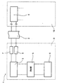
- the only figure shows a schematic Block diagram of the electronic according to the invention Control system, which preferably works digitally.
- the electronic control system 1 shown in the drawing has a data bus 2, via which various Control units are networked with each other.
- a first electronic Control unit 3 which is, for example, a act automatic transmission control in a motor vehicle can, to a second electronic control unit 4, for example an electronic engine control of the Motor vehicle, give safety-related signals, which For example, the setpoint one when changing gear Represent transmission torque setting.
- the first control unit 3 first generates a corresponding setpoint signal S and a setpoint signal S * complementary thereto, for example bitwise, and feeds it to a memory 5.
- the setpoint signal S and the complementary setpoint signal S * are to be generated by means of different modules of the hardware or software of the first control unit 3, that is to say in different ways, it also being provided that an additional signal Z or Z * indicating the path used is generated in each case . These additional signals are also fed to the memory 5.
- a third electronic control unit 6 combined with the first control unit 3 then reads the aforementioned signals S, S * , Z and Z * from the memory 5 in order to carry out various test operations.
- the complementarity of the signals S and S * can be checked, for example by adding these signals bit by bit. If the bitwise addition always leads to ZERO, the aforementioned bitwise complementarity is given.
- the value range of the signals S and S * can be checked, ie a query is made as to whether the signals are in a permissible and / or plausible range.
- the additional signals Z and Z * can be checked for plausibility.
- the paths used to generate the signals S and S * in the first control unit 3 have to be changed after predetermined time intervals.
- the third control unit 6 can thus check the permissibility of the paths used in each case using the signals Z and Z * .
- the third control unit 6 can calculate a parity signal P or P * for the digital signals S and S * , which reproduces how often the digital signals S and S * contain a digital ONE. These parity signals are stored in different locations in the memory 5.
- the third control unit 6 can generate so-called toggle bits T and T * , which can be complementary to one another in a predefinable manner. These toggle bits are switched at regular time intervals, for example after a predetermined number of pulses from a central clock (not shown) of the control system 1. These clock pulses can be sent to the control units via separate signal lines (not shown).
- the toggle bits T and T * are also recorded in the memory 5 at different locations.
- the first control unit 3 now reads the parity signals P and P * and the toggle bits T and T * from the memory 5 and carries out various security checks, for example addition tests and plausibility checks.
- the first control unit 3 If the first control unit 3 as the aforementioned signals detects without errors, it forwards the setpoint signal S, which Parity signal P and the toggle bit T to a buffer memory 7 further, which acts as a data bus transmission unit and puts the aforementioned signals on the data bus 2.
- the second control unit 4 only observes the setpoint signal S. when the transmitted parity signal P is the parity of the Signals S correctly and also the toggle bit T is present or plausible.
- the first control unit 3 can Correspondence of the signals sent by her with over the Check data bus 2 immediately returned signals.
- the second control unit 4 after receiving the Signals S, P and T an acknowledgment signal with the aforementioned signals dependent structure to the first Send control unit 3 back.
- an acknowledgment signal e.g. the received signal S are sent.
- the acknowledgment signal is faulty, i.e. as not matching the signals S, P and T this is synonymous with a communication error is present.
- control system 1 can if necessary an emergency operation can be switched.
- control unit 3 After an automatic shutdown, if applicable the control unit 3 or a switchover to emergency operation can the control system 1 again as part of service measures can be reset to normal operation.
- Elements 3 and 5 to 8 can be parts or areas a separate processor 9 designed or programmed his.
- the control units 3 and 6 can also be used in a single control unit as different software modules will be realized.
- the second control unit 4 can be part of a similar one Processor 10 may be formed.
- the data bus 2 can be provided as a so-called CAN bus.
- the memory 5 is preferably a RAM.
- the control system 1 described above preferably works digital.
Landscapes
- Physics & Mathematics (AREA)
- General Physics & Mathematics (AREA)
- Engineering & Computer Science (AREA)
- Automation & Control Theory (AREA)
- Safety Devices In Control Systems (AREA)
- Hardware Redundancy (AREA)
Abstract
Description
- die erste Steuereinheit das Sendesignal und ein dazu komplementäres Sendesignal auf unterschiedlichen Wegen erzeugt und zusammen mit zwei Zusatzsignalen, die für die Wege signifikant sind, zu einem Speicher leitet,
- eine dritte Steuereinheit, die Sende- und Zusatzsignale aus dem Speicher ausliest und überprüft und bei Erkennung eines Fehlers die erste Steuereinheit abschaltet bzw. bei korrekten Signalen verschiedenartige Prüf- bzw. Sicherheitssignale erzeugt und an einen Speicher leitet,
- die erste Steuereinheit die Prüf- bzw. Sicherheitssignale aus dem letztgenannten Speicher ausliest und überprüft und bei Erkennung eines Fehlers sich selbst abschaltet bzw. bei korrekten Prüf- bzw. Sicherheitssignalen das Sendesignal sowie zumindest eine vorgegebene Auswahl der Prüf- bzw. Sicherheitssignale der zweiten Einheit zuleitet.
Claims (6)
- Elektronisches Steuersystem (1) mit mehreren miteinander vernetzten bzw. kommunizierenden Steuereinheiten (3,4,6), wobei bei einer Übermittlung eines sicherheitsrelevanten Sendesignales (S) von einer ersten Steuereinheit (3) an eine zweite Steuereinheit (4) vorgesehen ist, daßdie erste Steuereinheit (3) das Sendesignal (S) und ein dazu komplementäres Sendesignal (S*) auf unterschiedlichen Wegen erzeugt und zusammen mit zwei Zusatzsignalen (Z,Z*), die für die Wege signifikant sind, an einen Speicher (5) leitet,eine dritte Steuereinheit (6) die Sende- und Zusatzsignale aus dem Speicher (5) ausliest und überprüft und bei Erkennung eines Fehlers die erste Steuereinheit (3) abschaltet bzw. bei korrekten Signalen verschiedenartige Prüf- bzw. Sicherheitssignale (P,P*,T,T*) erzeugt und an einen Speicher (5) leitet,die erste Steuereinheit (3) die Prüf- bzw. Sicherheitssignale aus dem letztgenannten Speicher (5) ausliest und überprüft und bei Erkennung eines Fehlers abschaltet bzw. bei korrekten Prüf- bzw. Sicherheitssignalen das Sendesignal (S) sowie zumindest eine vorgegebene Auswahl der Prüf- bzw. Sicherheitssignale (P,T) der zweiten Steuereinheit (4) zuleitet.
- Steuersysstem nach Anspruch 1,
dadurch gekennzeichnet,
daß die zweite Steuereinheit (4) die gesendete Auswahl der Prüf- bzw. Sicherheitssignale (S,T) prüft und bei Erkennung eines Fehlers das Sendesignal (S) unbeachtet läßt. - Steuersystem nach Anspruch 1 oder 2,
dadurch gekennzeichnet,
daß die zweite Steuereinheit (4) bei korrekten Prüf- bzw. Sicherheitssignalen (P,T) das Sendesignal (S) verarbeitet bzw. befolgt. - Steuersystem nach einem der Ansprüche 1 bis 3,
dadurch gekennzeichnet,
daß die zweite Steuereinheit (4) das empfangene Sendesignal (S) oder ein damit korreliertes Quittungssignal an die erste Steuereinheit (3) zurückleitet, welche das zugeleitete Signal prüft und das Steuersystem (1) bei Erkennung eines Fehlers auf eine Not- bzw. Ersatzbetriebsart umschaltet bzw. bei korrektem Signal weiterarbeiten läßt. - Steuersystem nach einem der Ansprüche 1 bis 4,
dadurch gekennzeichnet,
daß die erste Steuereinheit (3) bei korrekten Prüf- bzw. Sicherheitssignalen (P,P*,T,T*) das Sendesignal (S) sowie die Auswahl der Prüf- bzw. Sicherheitssignale (P,T) zur Weiterleitung an die zweite Steuereinheit (4) einem Datenbussender (7) zuführt, welcher die vorgenannten Signale an die zweite Steuereinheit (4) und an die erste Steuereinheit (3) weiter- bzw. zurücksendet, und daß die erste Steuereinheit (3) die gesendeten sowie die zurückgesendeten Signale vergleicht und sich bei Signalabweichungen abschaltet. - Steuersystem nach einem der Ansprüche 1 bis 5,
dadurch gekennzeichnet,
daß das Sendesignal (S) und das komplementäre Sendesignal (S*) zueinander bitweise komplementär sind.
Applications Claiming Priority (2)
| Application Number | Priority Date | Filing Date | Title |
|---|---|---|---|
| DE10006206A DE10006206A1 (de) | 2000-02-11 | 2000-02-11 | Elektronisches Steuersystem |
| DE10006206 | 2000-02-11 |
Publications (2)
| Publication Number | Publication Date |
|---|---|
| EP1124168A1 true EP1124168A1 (de) | 2001-08-16 |
| EP1124168B1 EP1124168B1 (de) | 2002-07-10 |
Family
ID=7630655
Family Applications (1)
| Application Number | Title | Priority Date | Filing Date |
|---|---|---|---|
| EP01102387A Expired - Lifetime EP1124168B1 (de) | 2000-02-11 | 2001-02-02 | Elektronisches Steuersystem |
Country Status (3)
| Country | Link |
|---|---|
| US (1) | US6934874B2 (de) |
| EP (1) | EP1124168B1 (de) |
| DE (2) | DE10006206A1 (de) |
Families Citing this family (15)
| Publication number | Priority date | Publication date | Assignee | Title |
|---|---|---|---|---|
| DE10142511B4 (de) * | 2001-08-30 | 2004-04-29 | Daimlerchrysler Ag | Fehlerbehandlung von Softwaremodulen |
| DE10223880B4 (de) * | 2002-05-29 | 2004-06-17 | Robert Bosch Gmbh | Verfahren zur gegenseitigen Überwachung von Komponenten eines dezentral verteilten Rechnersystems |
| DE10243319B4 (de) * | 2002-09-18 | 2004-08-12 | Daimlerchrysler Ag | Sichere Datenübertragung |
| JP4348950B2 (ja) * | 2003-01-23 | 2009-10-21 | 株式会社デンソー | 電子制御装置 |
| US7184864B2 (en) * | 2004-04-19 | 2007-02-27 | Haldex Brake Products Ltd. | Vehicle system control unit with auxiliary control capabilities |
| US20060200278A1 (en) * | 2005-03-02 | 2006-09-07 | Honeywell International Inc. | Generic software fault mitigation |
| DE102006029171A1 (de) * | 2006-06-24 | 2007-12-27 | Dr.Ing.H.C. F. Porsche Ag | Verfahren zum Betreiben von über einen Datenbus kommunizierenden Steuergeräten eines Kraftfahrzeugs |
| DE102007062974B4 (de) * | 2007-12-21 | 2010-04-08 | Phoenix Contact Gmbh & Co. Kg | Signalverarbeitungsvorrichtung |
| US9623817B2 (en) * | 2010-02-12 | 2017-04-18 | GM Global Technology Operations LLC | Method and system for controlling electrical systems of vehicles |
| US9000914B2 (en) | 2010-03-15 | 2015-04-07 | Welch Allyn, Inc. | Personal area network pairing |
| US8907782B2 (en) | 2010-06-30 | 2014-12-09 | Welch Allyn, Inc. | Medical devices with proximity detection |
| US8957777B2 (en) | 2010-06-30 | 2015-02-17 | Welch Allyn, Inc. | Body area network pairing improvements for clinical workflows |
| CN103455022B (zh) * | 2012-06-01 | 2015-12-02 | 北汽福田汽车股份有限公司 | 一种车载电控装置的诊断方法及装置 |
| US10903865B2 (en) | 2013-01-25 | 2021-01-26 | Infineon Technologies Ag | Signal interface and a signal processing system |
| US10756857B2 (en) * | 2013-01-25 | 2020-08-25 | Infineon Technologies Ag | Method, apparatus and computer program for digital transmission of messages |
Citations (5)
| Publication number | Priority date | Publication date | Assignee | Title |
|---|---|---|---|---|
| DE3600092A1 (de) * | 1985-01-25 | 1986-07-31 | Smiths Industries P.L.C., London | Signalverarbeitende schaltung |
| EP0322141A2 (de) * | 1987-12-22 | 1989-06-28 | LUCAS INDUSTRIES public limited company | System zur Doppelrechner-Übereinstimmungsüberprüfung |
| DE4114999A1 (de) * | 1991-05-08 | 1992-11-12 | Bosch Gmbh Robert | System zur steuerung eines kraftfahrzeuges |
| DE19653551C1 (de) * | 1996-12-20 | 1998-02-05 | Siemens Ag | Verfahren zur Überprüfung der Funktionsfähigkeit einer Recheneinheit |
| DE19743463A1 (de) * | 1997-10-01 | 1999-04-08 | Itt Mfg Enterprises Inc | Verfahren zur Fehlerkennung von Mikroprozessoren in Steuergeräten eines Kfz. |
Family Cites Families (5)
| Publication number | Priority date | Publication date | Assignee | Title |
|---|---|---|---|---|
| DE69231452T2 (de) * | 1991-01-25 | 2001-05-03 | Hitachi Process Computer Engineering, Inc. | Fehlertolerantes Rechnersystem mit Verarbeitungseinheiten die je mindestens drei Rechnereinheiten haben |
| US5909540A (en) * | 1996-11-22 | 1999-06-01 | Mangosoft Corporation | System and method for providing highly available data storage using globally addressable memory |
| DE19720618A1 (de) | 1997-05-16 | 1998-11-19 | Itt Mfg Enterprises Inc | Mikroprozessorsystem für Kfz-Regelungssysteme |
| US6633782B1 (en) * | 1999-02-22 | 2003-10-14 | Fisher-Rosemount Systems, Inc. | Diagnostic expert in a process control system |
| US6546508B1 (en) * | 1999-10-29 | 2003-04-08 | Advanced Micro Devices, Inc. | Method and apparatus for fault detection of a processing tool in an advanced process control (APC) framework |
-
2000
- 2000-02-11 DE DE10006206A patent/DE10006206A1/de not_active Withdrawn
-
2001
- 2001-02-02 EP EP01102387A patent/EP1124168B1/de not_active Expired - Lifetime
- 2001-02-02 DE DE50100010T patent/DE50100010D1/de not_active Expired - Lifetime
- 2001-02-12 US US09/780,608 patent/US6934874B2/en not_active Expired - Fee Related
Patent Citations (5)
| Publication number | Priority date | Publication date | Assignee | Title |
|---|---|---|---|---|
| DE3600092A1 (de) * | 1985-01-25 | 1986-07-31 | Smiths Industries P.L.C., London | Signalverarbeitende schaltung |
| EP0322141A2 (de) * | 1987-12-22 | 1989-06-28 | LUCAS INDUSTRIES public limited company | System zur Doppelrechner-Übereinstimmungsüberprüfung |
| DE4114999A1 (de) * | 1991-05-08 | 1992-11-12 | Bosch Gmbh Robert | System zur steuerung eines kraftfahrzeuges |
| DE19653551C1 (de) * | 1996-12-20 | 1998-02-05 | Siemens Ag | Verfahren zur Überprüfung der Funktionsfähigkeit einer Recheneinheit |
| DE19743463A1 (de) * | 1997-10-01 | 1999-04-08 | Itt Mfg Enterprises Inc | Verfahren zur Fehlerkennung von Mikroprozessoren in Steuergeräten eines Kfz. |
Also Published As
| Publication number | Publication date |
|---|---|
| DE10006206A1 (de) | 2001-08-30 |
| US20010020281A1 (en) | 2001-09-06 |
| US6934874B2 (en) | 2005-08-23 |
| EP1124168B1 (de) | 2002-07-10 |
| DE50100010D1 (de) | 2002-08-14 |
Similar Documents
| Publication | Publication Date | Title |
|---|---|---|
| EP1124168B1 (de) | Elektronisches Steuersystem | |
| DE19927635B4 (de) | Sicherheitsbezogenes Automatisierungsbussystem | |
| DE69431914T2 (de) | Steuerungs- und kommunikationsgerät | |
| EP1040028B1 (de) | Verfahren zur fehlererkennung von mikroprozessoren in steuergeräten eines kfz | |
| DE10037737B4 (de) | Verfahren und Vorrichtung zur sicheren einkanaligen Auswertung von Sensorsignalen | |
| DE3208573A1 (de) | 2 aus 3-auswahleinrichtung bei einem 3-rechnersystem | |
| EP1188096A1 (de) | Steuerungssystem zum steuern von sicherheitskritischen prozessen | |
| EP2109244A1 (de) | Verfahren zur sicherheitsgerichteten Übertragung Sicherheitsschaltgerät und Kontrolleinheit | |
| DE102018220605B4 (de) | Kraftfahrzeugnetzwerk und Verfahren zum Betreiben eines Kraftfahrzeugnetzwerks | |
| DE19922171B4 (de) | Kommunikationssystem mit einem Kommunikationsbus | |
| WO1999012771A1 (de) | Verfahren und vorrichtung zur steuerung der datenübertragung zwischen zwei in einem kraftfahrzeug vorhandenen modulen | |
| EP1055159B1 (de) | Fehlersichere prozesseingabe und prozessausgabe | |
| DE19619117A1 (de) | Steuersystem, insbesondere für Sicherheitssysteme in Kraftfahrzeugen, und Verfahren zum Austauschen von Informationen in einem Steuersystem | |
| DE2701925C3 (de) | Fahrzeugsteuerung mit zwei Bordrechnern | |
| DE102010027118A1 (de) | Weg- oder Winkelsensoreinheit und Lenksystem | |
| EP0965896B1 (de) | Numerische Steuerung mit einem räumlich getrennten Eingabegerät | |
| EP0978775B1 (de) | Verfahren zur sicheren Datenübertragung zwischen einer numerischen Steuerung und einem räumlich getrennten Gerät | |
| DE102017213401A1 (de) | Elektronische steuereinheit | |
| EP4048574B1 (de) | Auswertevorrichtung zur fehlertoleranten auswertung von sensorsignalen für ein motorsteuergerät einer kraftfahrzeuglenkung und kraftfahrzeuglenkung | |
| EP1227406A1 (de) | Transceiver mit Mitteln zum Fehlermanagement | |
| DE102007028767B4 (de) | Buskommunikationsschaltung zur sicheren seriellen Übertragung von Daten sowie deren Verwendung | |
| DE10343172B4 (de) | Datenübertragungsstrecke mit Einrichtung zur Prüfung der Datenintegrität | |
| EP2067668A1 (de) | Verfahren und Vorrichtung zur Plausibilisierung einer Auswertung von sicherheitsrelevanten Signalen für ein Kraftfahrzeug | |
| EP4131848A1 (de) | Verfahren und verschaltung zum betrieb eines netzwerks oder netzwerkabschnitts | |
| EP1114533B1 (de) | Verfahren und vorrichtung zur überwachung von signalen bei vernetzten systemen |
Legal Events
| Date | Code | Title | Description |
|---|---|---|---|
| PUAI | Public reference made under article 153(3) epc to a published international application that has entered the european phase |
Free format text: ORIGINAL CODE: 0009012 |
|
| 17P | Request for examination filed |
Effective date: 20010523 |
|
| AK | Designated contracting states |
Kind code of ref document: A1 Designated state(s): DE FR GB IT |
|
| AX | Request for extension of the european patent |
Free format text: AL;LT;LV;MK;RO;SI |
|
| GRAG | Despatch of communication of intention to grant |
Free format text: ORIGINAL CODE: EPIDOS AGRA |
|
| 17Q | First examination report despatched |
Effective date: 20011120 |
|
| GRAG | Despatch of communication of intention to grant |
Free format text: ORIGINAL CODE: EPIDOS AGRA |
|
| GRAH | Despatch of communication of intention to grant a patent |
Free format text: ORIGINAL CODE: EPIDOS IGRA |
|
| GRAH | Despatch of communication of intention to grant a patent |
Free format text: ORIGINAL CODE: EPIDOS IGRA |
|
| AKX | Designation fees paid |
Free format text: DE FR GB IT |
|
| GRAA | (expected) grant |
Free format text: ORIGINAL CODE: 0009210 |
|
| AK | Designated contracting states |
Kind code of ref document: B1 Designated state(s): DE FR GB IT |
|
| REG | Reference to a national code |
Ref country code: GB Ref legal event code: FG4D Free format text: NOT ENGLISH |
|
| REF | Corresponds to: |
Ref document number: 50100010 Country of ref document: DE Date of ref document: 20020814 |
|
| GBT | Gb: translation of ep patent filed (gb section 77(6)(a)/1977) |
Effective date: 20020814 |
|
| ET | Fr: translation filed | ||
| PLBE | No opposition filed within time limit |
Free format text: ORIGINAL CODE: 0009261 |
|
| STAA | Information on the status of an ep patent application or granted ep patent |
Free format text: STATUS: NO OPPOSITION FILED WITHIN TIME LIMIT |
|
| 26N | No opposition filed |
Effective date: 20030411 |
|
| REG | Reference to a national code |
Ref country code: FR Ref legal event code: CA Ref country code: FR Ref legal event code: CD |
|
| PGFP | Annual fee paid to national office [announced via postgrant information from national office to epo] |
Ref country code: DE Payment date: 20110218 Year of fee payment: 11 Ref country code: IT Payment date: 20110221 Year of fee payment: 11 Ref country code: FR Payment date: 20110302 Year of fee payment: 11 |
|
| PGFP | Annual fee paid to national office [announced via postgrant information from national office to epo] |
Ref country code: GB Payment date: 20110217 Year of fee payment: 11 |
|
| GBPC | Gb: european patent ceased through non-payment of renewal fee |
Effective date: 20120202 |
|
| REG | Reference to a national code |
Ref country code: FR Ref legal event code: ST Effective date: 20121031 |
|
| PG25 | Lapsed in a contracting state [announced via postgrant information from national office to epo] |
Ref country code: IT Free format text: LAPSE BECAUSE OF NON-PAYMENT OF DUE FEES Effective date: 20120202 |
|
| REG | Reference to a national code |
Ref country code: DE Ref legal event code: R119 Ref document number: 50100010 Country of ref document: DE Effective date: 20120901 |
|
| PG25 | Lapsed in a contracting state [announced via postgrant information from national office to epo] |
Ref country code: FR Free format text: LAPSE BECAUSE OF NON-PAYMENT OF DUE FEES Effective date: 20120229 Ref country code: GB Free format text: LAPSE BECAUSE OF NON-PAYMENT OF DUE FEES Effective date: 20120202 |
|
| PG25 | Lapsed in a contracting state [announced via postgrant information from national office to epo] |
Ref country code: DE Free format text: LAPSE BECAUSE OF NON-PAYMENT OF DUE FEES Effective date: 20120901 |