EP1124150B2 - Surgical microscope - Google Patents
Surgical microscope Download PDFInfo
- Publication number
- EP1124150B2 EP1124150B2 EP00102901.6A EP00102901A EP1124150B2 EP 1124150 B2 EP1124150 B2 EP 1124150B2 EP 00102901 A EP00102901 A EP 00102901A EP 1124150 B2 EP1124150 B2 EP 1124150B2
- Authority
- EP
- European Patent Office
- Prior art keywords
- data
- light
- power
- microscope
- connection
- Prior art date
- Legal status (The legal status is an assumption and is not a legal conclusion. Google has not performed a legal analysis and makes no representation as to the accuracy of the status listed.)
- Expired - Lifetime
Links
Images

Classifications
-
- G—PHYSICS
- G02—OPTICS
- G02B—OPTICAL ELEMENTS, SYSTEMS OR APPARATUS
- G02B21/00—Microscopes
- G02B21/0004—Microscopes specially adapted for specific applications
- G02B21/0012—Surgical microscopes
Definitions
- the invention relates to a surgical microscope according to the preamble of claim 1.
- a surgical microscope in the sense of the invention is to be understood as a microscope which is movable with respect to an object. And therefore has a certain flexibility in any connections with external devices. Very often, such microscopes are used in operations. Frequently, such microscopes are also found in industrial or commercial applications.
- Such microscopes often have integrated illumination, with the light source installed in the microscope. However, the latter is often also outsourced in order to minimize the heating, the weight and the housing dimension in the region of the microscope body. In such constructions, the light is directed via an optical fiber from an external light source to the microscope body and through it to the surgical field.
- microscopes and built-in video cameras are often equipped with remote-controlled adjustment mechanisms or actuators, the one hand, electric drives, on the other hand, however, sensors or the like. include, whose signals are evaluated in external controls or circuits.
- connection between the external devices with the microscope body or with the terminals located thereon via flexible lines such as optical fibers, electrical cables, electronic data lines, etc.
- Such a microscope with a power supply, a light guide for surgical lighting, and an electronic data line is for example from utility model DE 9 405 820 U known.
- the applicant has already come up with solutions that should reduce the situation.
- the OH-stand of the applicant had provided a flexible hose between tripod arms through which all the different cables were pulled.
- this hose was relatively bulky and inflexible and so far not optimally used space, as he had to be made large enough for the retrofitting of an indefinite number of cables, even if not all cables were retracted.
- the tube increased the weight of the affected stand arms by its own weight.
- the invention is therefore the object of the connection between the external devices and the microscope body as easily as possible, easy to move and retrofit and to realize with as few cables.
- a preferred construction of a cable according to the invention is coaxially multilayer, one of the layers, but preferably the core of the cable - is designed as a mirror or fiber optic or as a liquid light guide, while at least two layers as at least two-pole power cable are formed.
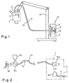
- Fig.1 shows a symbolic structure with a stand 11, which carries a microscope body 1 and various external devices 12. These include, for example, a computer 13 for control and measuring tasks; a light source 10, which is also referred to here by way of example as a power supply unit 5, because from there a luminous flux is directed via a power connection 4c or a light guide the luminous flux to the microscope body 1 and an operating field; a control device, which is connected, for example, via a data connection 7c integrated in the light guide 4c according to the invention with remote-controlled drives in the microscope.
- the microscope accordingly comprises a connection 3 for the power connection 4c and a connection 6 for the data connection.
- the data connection is realized in this example via optoelectronic converters 9a and 9b, which convert electrical signals into optical signals or vice versa. These signals are reflected or reflected by means of beam splitters or mirrors 14a and 14b into the optical waveguide 4c so that both the luminous flux from the light source and the optical signals from the transducer 9a are transmitted to the microscope, or optical signals the converter 9b are sent in the other direction to the computer 13 and to the control unit 2.
- the power to be transmitted e.g. Light and / or electrical power while the data can be electrical and / or light optical signals.
- the data can be electrical and / or light optical signals.
- electrical signals are transmitted by light modulation via the light guide.
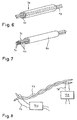
- Figure 7 shows a rel. simple structure that provides no integrated luminous flux transmission, but an electrical power transmission in power wires 4a of a multi-core cable 8a, while the data transmission takes place in data lines 7a of the same cable 8a.
- Figure 8 uses only a two-pole power cable 4b, which is twisted for improved Abschirrmrial. At the same time, a high-frequency (relative to the power flow) data transmission is undertaken via this power cable, with corresponding signal couplers 15a and 15b being provided for this purpose, which are connected at the other end to the connection 6 or to the computer 13 or the control unit 2.
- Such signal couplers are optionally also in structures of Fig.3-5 provided, in these structures, the electrical wiring should also be used for data purposes.
- Figure 6 shows a light guide 4e, which has an electric, bipolar cable 4g as a soul.
- Figure 3 shows another optical fiber in which a two-pole cable (a coaxial cable in this example) 4h is wound as a reinforcement around the optical fiber 4d.
- a two-pole cable (a coaxial cable in this example) 4h is wound as a reinforcement around the optical fiber 4d.
- an outer tube 16 is still wound as outer layer.
- Figure 4 shows a detail of the coaxial cable after Figure 3 , which of course could be used in addition to a power transmission for a data transmission - but with lower bandwidth than light - could be used, which is intended in this example to a data transmission via the light guide 4d.
- Figure 5 shows a combination of example Figure 3 and Figure 6 with a single-pole reinforcement 4f2, which can also be formed, for example, from a conventional corrugated metal hose, and a single-pole core 4f1 within the optical waveguide 4e.
- a single-pole reinforcement 4f2 which can also be formed, for example, from a conventional corrugated metal hose, and a single-pole core 4f1 within the optical waveguide 4e.
- this structure there is also a favorable Abschirrm Sign by the coaxial structure of the electrical conductors 4f1 and 4f2. It is therefore also possible for data to be transmitted without problems and interference-free, so that, if appropriate, data transmission via the optical waveguide 4e can be dispensed with.
Description
Die Erfindung betrifft ein Operationsmikroskop gemäss dem Oberbegriff des Anspruches 1.
Unter Operationsmikroskop im Sinne der Erfindung ist ein Mikroskop zu verstehen, das in Bezug auf ein Objekt beweglich ist. Und deshalb eine gewisse Flexibilität bei allfälligen Verbindungen mit externen Geräten aufweist. Sehr häufig werden solche Mikroskope bei Operationen eingesetzt. Häufig findet man solche Mikroskope auch bei industriellen oder gewerblichen Anwendungen.The invention relates to a surgical microscope according to the preamble of
A surgical microscope in the sense of the invention is to be understood as a microscope which is movable with respect to an object. And therefore has a certain flexibility in any connections with external devices. Very often, such microscopes are used in operations. Frequently, such microscopes are also found in industrial or commercial applications.
Solche Mikroskope verfügen häufig über eine integrierte Beleuchtung, bei der die Lichtquelle im Mikroskop eingebaut ist. Letztere ist oftmals jedoch auch ausgelagert, um im Bereich des Mikroskopkörpers die Erwärmung, das Gewicht und die Gehäusedimension gering zu halten. Bei solchen Aufbauten wird das Licht über einen Lichtleiter von einer externen Lichtquelle zum Mikroskopkörper und durch diesen durch auf das Operationsfeld gelenkt.Such microscopes often have integrated illumination, with the light source installed in the microscope. However, the latter is often also outsourced in order to minimize the heating, the weight and the housing dimension in the region of the microscope body. In such constructions, the light is directed via an optical fiber from an external light source to the microscope body and through it to the surgical field.
Weiters sind solche Mikroskope und darin eingebaute Videokameras häufig mit fernbedienbaren Verstellmechanismen bzw. Aktuatoren ausgerüstet, die einerseits elektrische Antriebe, andererseits jedoch auch Sensoren o.dgl. umfassen, deren Signale in externen Steuerungen bzw. Schaltungen ausgewertet werden.Furthermore, such microscopes and built-in video cameras are often equipped with remote-controlled adjustment mechanisms or actuators, the one hand, electric drives, on the other hand, however, sensors or the like. include, whose signals are evaluated in external controls or circuits.
Häufig befinden sich solche Mikroskope an den Auslegearmen von Stativen, während die externen Geräte und Steuerungen im Ständerbereich des Stativs untergebracht sind.Often such microscopes are located on the extension arms of tripods, while the external devices and controls are housed in the stand area of the tripod.
Die Verbindung zwischen den externen Geräten mit dem Mikroskopkörper bzw. mit den daran befindlichen Anschlüssen erfolgt über flexible Leitungen wie Lichtleitern, elektrische Kabel, elektronische Datenleitungen etc. Ein solches Mikroskop mit einer Stromversorgung, einem Lichtleitkabel zur Operationsbeleuchtung, und einer elektronischen Datenleitung ist beispielsweise aus der Gebrauchsmusterschrift
In der Regel finden sich eine Vielzahl von solchen Leitungen, die in verschiedenen Anwendungsfällen störend sind.In general, there are a variety of such lines, which are disturbing in various applications.
Sie behindern fallweise die Sicht, weisen ein grosses Gewicht auf, führen zu Verklemmungen und Bewegungseinschränkungen und sehen zu dem unordentlich aus. Ausserdem sind sie störanfällig bzw. können durch Beschädigung Störfälle verursachen. Im Bereich der Operationsmikroskopie führen sie zu vergrösserten Oberflächen, die den Gesamtaufbau somit schmutzanfälliger machen.They obstruct the view occasionally, have a high weight, lead to jamming and movement restrictions and look messy to the. In addition, they are prone to failure or can cause damage due to damage. In the field of surgical microscopy, they lead to enlarged surfaces, which make the overall structure more susceptible to dirt.
Es wurden von der Anmelderin bereits Lösungsansätze gemacht, die den Misstand verringern sollten. Das OH-Stativ der Anmelderin hatte zwischen Stativarmen einen flexiblen Schlauch vorgesehen, durch den alle verschiedenen Kabel gezogen waren. Dieser Schlauch war jedoch relativ voluminös und unflexibel und insofern nicht optimal platznutzend, als er für die Nachrüstung einer unbestimmte Anzahl von Kabeln genügend gross gemacht werden musste, auch wenn nicht alle Kabel eingezogen waren. Ausserdem erhöhte der Schlauch das Gewicht der betroffenen Stativarme um sein Eigengewicht.The applicant has already come up with solutions that should reduce the situation. The OH-stand of the applicant had provided a flexible hose between tripod arms through which all the different cables were pulled. However, this hose was relatively bulky and inflexible and so far not optimally used space, as he had to be made large enough for the retrofitting of an indefinite number of cables, even if not all cables were retracted. In addition, the tube increased the weight of the affected stand arms by its own weight.
Der Erfindung liegt somit die Aufgabe zugrunde, die Verbindung zwischen den externen Geräten und dem Mikroskopkörper möglichst leicht, leicht beweglich und nachrüstbar und mit möglichst wenig Kabeln zu realisieren.The invention is therefore the object of the connection between the external devices and the microscope body as easily as possible, easy to move and retrofit and to realize with as few cables.
Die Kombination der jew. Merkmale der Ansprüche 1 o.2 löst diese Hauptaufgabe nach einer Baugrössen- u. gleichz. Gewichtsreduktion.The combination of the jew. Features of
Weiterentwickelte bzw. weiter verbesserte Lösungen mit weitergehender Integration und weitergehenden Vorteilen gegenüber dem Stand der Technik ergeben sich aus den abhängigen Ansprüchen und der Figurenbeschreibung.Further developed or further improved solutions with further integration and further advantages over the prior art result from the dependent claims and the description of the figures.
Ein bevorzugter Aufbau eines erfindungsgemässen Kabels, dass gegebenenfalls auch unabhängig von der Erfindung eingesetzt werden kann, ist koaxial mehrlagig, wobei einer Der Lagen, vorzugsweise jedoch der Kern des Kabels - als Spiegel- oder Faseroptik oder als Flüssigkeitslichtleiter ausgebildet ist, während wenigstens zwei Lagen als wenigstens zweipoliges Leistungskabel ausgebildet sind.A preferred construction of a cable according to the invention, which can optionally also be used independently of the invention, is coaxially multilayer, one of the layers, but preferably the core of the cable - is designed as a mirror or fiber optic or as a liquid light guide, while at least two layers as at least two-pole power cable are formed.
An den Lichtleiteteil eines solchen Kabel schliessen bevorzugt elektro-optische Wandler für Steuerungs-, Sensorik- und Videosignalübertragung, während an den Leistungsteil die Spannungsversorgung anschliesst.To the light guide part of such a cable close preferably electro-optical converter for control, sensor and video signal transmission, while the power supply is connected to the power supply.
Weitere Verbesserungen und erfindungsgemässe Details ergeben sich aus der Zeichnung, die ein erfindungsgemässes Ausführungsbeispiel darstellt.Further improvements and inventive details will become apparent from the drawing, which represents an embodiment of the invention.
Es zeigen dabei:
- Fig. 1
- ein symbolisiertes, komplettes, erfindungsgemässes Operationsmikroskop an einem Stativ mit entsprechenden externen Geräten;
- Fig. 2
- ein Detail eines erfindungsgemäss abgewandelten Lichtleiters mit elektrooptischen Datenwandlern und Ein- bzw. Ausspiegelungsvorrichtungen;
- Fig. 3
- einen anderen Lichtleiter mit besonderer Armierung;
- Fig. 4
- ein Detail der Armierung nach
Fig.3 ; - Fig. 5
- eine Variante zum Lichtleiter nach
Fig.3 ; - Fig. 6
- eine weitere Variante zum Lichtleiter nach
Fig.3 ; - Fig. 7
- ein mehradriges Kabel als Leistungs- und Datenträger; .
- Fig. 8
- ein zweipoliges Kabel, das sowohl als Leistungs-, als auch als Datenleitung dient.
- Fig. 1
- a symbolized, complete, inventive surgical microscope on a tripod with corresponding external devices;
- Fig. 2
- a detail of an inventive modified light guide with electro-optical data converters and input or Ausspiegelungsvorrichtungen;
- Fig. 3
- another light guide with special reinforcement;
- Fig. 4
- a detail of the reinforcement after
Figure 3 ; - Fig. 5
- a variant to the light guide after
Figure 3 ; - Fig. 6
- another variant to the light guide after
Figure 3 ; - Fig. 7
- a multi-core cable as a power and data carrier; ,
- Fig. 8
- a two-pole cable that serves as both power and data line.
Die Figuren werden übergreifend beschrieben. Gleiche Teile tragen gleiche Bezugszeichen; unterschiedliche Teile mit vom Prinzip her gleichen Funktionen tragen gleiche Bezugszeichen mit unterschiedlichen Indizes. Die Figuren schränken die Erfindung nicht ein, sondern sind vielmehr als mögliche Ausführungsbeispiele gedacht.The figures are described comprehensively. Like parts bear the same reference numerals; different parts with the same functions in principle have the same reference numerals with different indices. The figures do not limit the invention, but rather are intended as possible embodiments.
Die Datenverbindung ist bei diesem Beispiel realisiert über optoelektronische Wandler 9a und 9b, die elektrische Signale in optische Signale umwandeln bzw. umgekehrt. Diese Signale werden über Strahlenteiler oder Spiegel 14a und 14b in den Lichtleiter 4c ein- bzw. ausgespiegelt, so dass über diesen sowohl der Lichtstrom aus der Lichtquelle, als auch die optischen Signale aus dem Wandler 9a zum Mikroskop gesandt werden, bzw. optische Signale aus dem Wandler 9b in die andere Richtung zum Rechner 13 bzw. zum Steuergerät 2 gesandt werden.The data connection is realized in this example via
Im Rahmen der Erfindung liegen verschiedenste Kombinationen, so kann die Leistung, die übertragen werden soll, z.B. Licht- und/oder elektrische Leistung sein, während die Daten elektrische und/oder lichtoptische Signale sein können. Wobei dies umfasst, dass elektrische Signale durch Lichtmodulation über den Lichtleiter übertragen werden.In the context of the invention are various combinations, so the power to be transmitted, e.g. Light and / or electrical power while the data can be electrical and / or light optical signals. Whereby this includes that electrical signals are transmitted by light modulation via the light guide.
Die Möglichkeiten werden auszugsweise an Hand der Beispiele in den
Solche Signalkoppler sind gegebenenfalls auch bei Aufbauten der
Die oben angesprochenen Signale umfassen:
- bevorzugt amplitudenmodulierter/s oder frequenzmodulierter/s Strom, oder Licht einschliesslich nicht sichtbarer Lichtwellenbereiche, wie z.B. wie z.B. Infrarot.
- preferably amplitude modulated / s or frequency modulated / s current, or light including non-visible light wave ranges, such as eg infrared.
Dabei ist durch die Erfindung umfasst, dass einerseits die leistungsmässig fliessenden elektrischen oder Licht-Ströme entsprechend moduliert werden, und/oder dass parallel zu diesen fliessenden Leistungsströmen elektrische bzw. lichtoptische Signale über die jeweils gleiche Leitung geschickt werden.
- 1
- Mikroskopkörper
- 2
- Steuergerät
- 3
- Leistungsanschluss
- 4
- Leistungsverbindung
- 5
- Leistungsversorgungseinheit
- 6
- Datenanschluss
- 7
- Datenverbindung
- 8
- Kabel
- 9
- Einrichtung für das Umwandeln; elektrooptische Wandler
- 10
- Lichtquelle
- 11
- Stativ
- 12
- externe Geräte
- 13
- Rechner
- 14
- Strahlenteiler
- 15
- Signalkoppler
- 16
- Hüllschlauch
- 1
- microscope body
- 2
- control unit
- 3
- power connection
- 4
- power connection
- 5
- Power supply unit
- 6
- data port
- 7
- Data Connection
- 8th
- electric wire
- 9
- Device for converting; electro-optical converters
- 10
- light source
- 11
- tripod
- 12
- external devices
- 13
- computer
- 14
- beamsplitter
- 15
- signal coupler
- 16
- buffer tube
Claims (8)
- A surgical microscope with a microscope body (1) and at least one power port (3) thereon and with a power connection (4) for receiving power from a power supply unit (5) outside the microscope body (1) and with at least one data port (6) on the microscope body (1) and a data connection (7) for transmitting / receiving and/or sending data to/from the microscope body (1) from/to a control device (2), characterised in that the power connection (4) and the data connection (7) are integrally formed and in that the power connection is a light conductor (4c; 4d; 4e) and the power is a light flux, and the data is electrical signals, and in that the data connection is a light wave data connection (7c; 7d), which is equipped with means for converting electrical signals into light-optical signals so that in the operating state electrical signals between the data port (6) and the control device (2) are converted into light signals and vice versa, and transmitted.
- The surgical microscope with a microscope body (1) and at least one power port (3) thereon and with a power connection (4) for receiving power from a power supply unit (5) outside the microscope body (1) and with at least one data port (6) on the microscope body (1) and a data connection (7) for transmitting / receiving and/or sending data to/from the microscope body (1) from/to a control device (2), characterised in that the power connection (4) and the data connection (7) are integrally formed, and in that the power connection comprises a light conductor (4d; 4e) and an electrical line (4f; 4g; 4h) and the power is electrical power and light flux, and where the data is electrical signals, and in that the light conductor (4d; 4e) is equipped at either end with means (9) for converting electrical signals into light-optical signals, so that in the operating state electrical signals converted into light signals between the microscope body (1) and the control device (2) are transmitted via the light conductor (4d; 4e).
- The microscope according to claim 1 or 2, characterised in that the power connection (4a) utilises a part of the multi-core cable (8), whilst the data connection (7a) utilises another part of the same cable (8).
- The microscope according to claim 1, characterised in that the light wave data connection (7c; 7d) is established via the same light conductor (4c; 4d) as the light flux power connection.
- The microscope according to claim 2, characterised in that the electrical line (4f; 4g; 4h) is implemented as a sheath (4f2; 4h) and/or as a core (4f1; 4g) for the light conductor (4d; 4e).
- The microscope according to one of claims 1 - 5, where a light source (10) for generating a surgical field illumination is assigned to the light conductor (4c).
- The microscope according to one of the preceding claims, where sensors and/or drives for controlling the microscope or a tripod are assigned to the power connection (4) and/or the data connection (7).
- The surgical microscope according to one of the preceding claims with a light source (10) for surgical field illumination, which is connectable or connected with the microscope body (1) via a light conductor (4c; 4d), and with drives and/or sensors, which are connectable or connected via data tracks with at least one control device (2), characterised in that the data tracks comprise opto-electronic data converters (9a, 9b), which are connected or connectable therewith at either end of the light conductor (4c, 4d), possibly via couplings, so that in the operating state both the data transmission between the microscope body (1) and the control device (2) and the light transmission between the light source (10) and the microscope body (1) is effected via the light conductor.
Priority Applications (2)
| Application Number | Priority Date | Filing Date | Title |
|---|---|---|---|
| EP00102901.6A EP1124150B2 (en) | 2000-02-12 | 2000-02-12 | Surgical microscope |
| DE50014197T DE50014197D1 (en) | 2000-02-12 | 2000-02-12 | surgical microscope |
Applications Claiming Priority (1)
| Application Number | Priority Date | Filing Date | Title |
|---|---|---|---|
| EP00102901.6A EP1124150B2 (en) | 2000-02-12 | 2000-02-12 | Surgical microscope |
Publications (3)
| Publication Number | Publication Date |
|---|---|
| EP1124150A1 EP1124150A1 (en) | 2001-08-16 |
| EP1124150B1 EP1124150B1 (en) | 2007-03-28 |
| EP1124150B2 true EP1124150B2 (en) | 2015-02-18 |
Family
ID=8167837
Family Applications (1)
| Application Number | Title | Priority Date | Filing Date |
|---|---|---|---|
| EP00102901.6A Expired - Lifetime EP1124150B2 (en) | 2000-02-12 | 2000-02-12 | Surgical microscope |
Country Status (2)
| Country | Link |
|---|---|
| EP (1) | EP1124150B2 (en) |
| DE (1) | DE50014197D1 (en) |
Families Citing this family (3)
| Publication number | Priority date | Publication date | Assignee | Title |
|---|---|---|---|---|
| DE10202125A1 (en) * | 2002-01-22 | 2003-07-31 | Leica Microsystems | Transmission device for an operating microscope |
| JP4073249B2 (en) * | 2002-05-17 | 2008-04-09 | オリンパス株式会社 | Surgery system |
| US7248402B2 (en) | 2002-12-09 | 2007-07-24 | Carl Zeiss Surgical Gmbh | Surgical microscopy system |
Citations (2)
| Publication number | Priority date | Publication date | Assignee | Title |
|---|---|---|---|---|
| GB2302184A (en) † | 1995-06-09 | 1997-01-08 | Gen Electric Plc | Composite cable for electric power and communication signals |
| US5834698A (en) † | 1995-08-30 | 1998-11-10 | Mitsuba Corporation | Composite cable with built-in signal and power cables |
Family Cites Families (5)
| Publication number | Priority date | Publication date | Assignee | Title |
|---|---|---|---|---|
| JPH0748090B2 (en) * | 1987-04-09 | 1995-05-24 | オリンパス光学工業株式会社 | Surgical microscope |
| JPH0756003Y2 (en) * | 1988-10-07 | 1995-12-25 | オリンパス光学工業株式会社 | Surgical microscope |
| DE9405820U1 (en) * | 1994-04-08 | 1994-06-01 | Moeller J D Optik | Surgical microscope unit |
| IL122111A (en) | 1997-11-04 | 2004-06-01 | Sightline Techn Ltd | Video rectoscope |
| DE29910795U1 (en) | 1999-06-21 | 1999-09-02 | Wolf Gmbh Richard | Electronic endoscope |
-
2000
- 2000-02-12 DE DE50014197T patent/DE50014197D1/en not_active Expired - Lifetime
- 2000-02-12 EP EP00102901.6A patent/EP1124150B2/en not_active Expired - Lifetime
Patent Citations (2)
| Publication number | Priority date | Publication date | Assignee | Title |
|---|---|---|---|---|
| GB2302184A (en) † | 1995-06-09 | 1997-01-08 | Gen Electric Plc | Composite cable for electric power and communication signals |
| US5834698A (en) † | 1995-08-30 | 1998-11-10 | Mitsuba Corporation | Composite cable with built-in signal and power cables |
Non-Patent Citations (7)
| Title |
|---|
| Computerzeichnung Kabel (23.01.1998) † |
| Computerzeichnung Stativ NC4-2 (31.7.1997) † |
| Computerzeichnung Stativ NC4-3 (31.7.1997) † |
| Computerzeichnung Statvi NC4-1 (31.7.1997) † |
| Firmensprospekt STN (9/98) † |
| Installationsreport (16.4.1999) † |
| Kommissionierbeleg (22.3.1999) † |
Also Published As
| Publication number | Publication date |
|---|---|
| DE50014197D1 (en) | 2007-05-10 |
| EP1124150B1 (en) | 2007-03-28 |
| EP1124150A1 (en) | 2001-08-16 |
Similar Documents
| Publication | Publication Date | Title |
|---|---|---|
| DE102006000702B4 (en) | connection device | |
| EP0824714B1 (en) | Electrical plug device | |
| DE102012212254B3 (en) | Connector for cable-free signal transmission | |
| DE19947811A1 (en) | Endoscope with means for modulated optical signaling between operator end and remote end to remove the requirement for additional electrical connectors between the two ends so that only an optical fiber connector is needed | |
| EP0391948B1 (en) | Cable | |
| DE60035396T2 (en) | Variable optical delay line with a microelectromechanical system | |
| EP1124150B2 (en) | Surgical microscope | |
| DE3239011A1 (en) | METHOD FOR MANUFACTURING AN OPTICAL COUPLING DEVICE, IN PARTICULAR METHOD FOR REDUCING THE WALL THICKNESS OF SHEETS OF LIGHTWAVE LADDER FIBERGLASS EXISTING FROM QUARTZ GLASS | |
| DE102008019758B3 (en) | connection device | |
| DE19636162A1 (en) | Connection cable for control units | |
| DE3326406A1 (en) | Optical transmitting and receiving unit | |
| EP1284427A3 (en) | Light optical control device | |
| EP0480078A1 (en) | Measuring device with non-electrical signal- and energy transfer | |
| US20010043392A1 (en) | Surgical microscope | |
| DE202008005461U1 (en) | connection device | |
| EP1269237B1 (en) | Optical wave guide transmission path with passive direction-dependent attenuation | |
| EP1665307A2 (en) | Arrangement for monitoring electric devices on stray light arcs | |
| DE102021109208A1 (en) | Multi-mode waveguide system and connector for integrated optical circuits | |
| WO2008006402A1 (en) | Connector | |
| EP2044812B1 (en) | Lighting system comprising a light sensor for controlling a ballast | |
| DE10217059B4 (en) | Measured value transmission for high voltage power supplies for electrostatic precipitators | |
| DE4101962A1 (en) | Data transmission system with optical fibre(s) - connects both ends of fibres fitted in separate plug housing to electro-optical transducer | |
| EP1787406B1 (en) | Connection unit for connecting an electronic device to an optical data bus | |
| CH701871A1 (en) | Electro-optical cable. | |
| DE60026604T2 (en) | NETWORK FOR DISTRIBUTING SIGNALS TO A VARIETY OF USERS |
Legal Events
| Date | Code | Title | Description |
|---|---|---|---|
| PUAI | Public reference made under article 153(3) epc to a published international application that has entered the european phase |
Free format text: ORIGINAL CODE: 0009012 |
|
| AK | Designated contracting states |
Kind code of ref document: A1 Designated state(s): CH DE FR GB LI |
|
| AX | Request for extension of the european patent |
Free format text: AL;LT;LV;MK;RO;SI |
|
| 17P | Request for examination filed |
Effective date: 20020122 |
|
| AKX | Designation fees paid |
Free format text: CH DE FR GB LI |
|
| GRAP | Despatch of communication of intention to grant a patent |
Free format text: ORIGINAL CODE: EPIDOSNIGR1 |
|
| GRAS | Grant fee paid |
Free format text: ORIGINAL CODE: EPIDOSNIGR3 |
|
| GRAA | (expected) grant |
Free format text: ORIGINAL CODE: 0009210 |
|
| AK | Designated contracting states |
Kind code of ref document: B1 Designated state(s): CH DE FR GB LI |
|
| REG | Reference to a national code |
Ref country code: GB Ref legal event code: FG4D Free format text: NOT ENGLISH |
|
| REG | Reference to a national code |
Ref country code: CH Ref legal event code: EP |
|
| REF | Corresponds to: |
Ref document number: 50014197 Country of ref document: DE Date of ref document: 20070510 Kind code of ref document: P |
|
| GBV | Gb: ep patent (uk) treated as always having been void in accordance with gb section 77(7)/1977 [no translation filed] |
Effective date: 20070328 |
|
| EN | Fr: translation not filed | ||
| PLBI | Opposition filed |
Free format text: ORIGINAL CODE: 0009260 |
|
| 26 | Opposition filed |
Opponent name: CARL ZEISS AG Effective date: 20071221 |
|
| PLAX | Notice of opposition and request to file observation + time limit sent |
Free format text: ORIGINAL CODE: EPIDOSNOBS2 |
|
| PG25 | Lapsed in a contracting state [announced via postgrant information from national office to epo] |
Ref country code: FR Free format text: LAPSE BECAUSE OF FAILURE TO SUBMIT A TRANSLATION OF THE DESCRIPTION OR TO PAY THE FEE WITHIN THE PRESCRIBED TIME-LIMIT Effective date: 20071116 Ref country code: GB Free format text: LAPSE BECAUSE OF FAILURE TO SUBMIT A TRANSLATION OF THE DESCRIPTION OR TO PAY THE FEE WITHIN THE PRESCRIBED TIME-LIMIT Effective date: 20070328 |
|
| PLBB | Reply of patent proprietor to notice(s) of opposition received |
Free format text: ORIGINAL CODE: EPIDOSNOBS3 |
|
| REG | Reference to a national code |
Ref country code: CH Ref legal event code: PL |
|
| PG25 | Lapsed in a contracting state [announced via postgrant information from national office to epo] |
Ref country code: CH Free format text: LAPSE BECAUSE OF NON-PAYMENT OF DUE FEES Effective date: 20080229 Ref country code: LI Free format text: LAPSE BECAUSE OF NON-PAYMENT OF DUE FEES Effective date: 20080229 |
|
| PG25 | Lapsed in a contracting state [announced via postgrant information from national office to epo] |
Ref country code: FR Free format text: LAPSE BECAUSE OF FAILURE TO SUBMIT A TRANSLATION OF THE DESCRIPTION OR TO PAY THE FEE WITHIN THE PRESCRIBED TIME-LIMIT Effective date: 20070328 |
|
| PLAY | Examination report in opposition despatched + time limit |
Free format text: ORIGINAL CODE: EPIDOSNORE2 |
|
| PLAT | Information related to reply to examination report in opposition deleted |
Free format text: ORIGINAL CODE: EPIDOSDORE3 |
|
| PLBC | Reply to examination report in opposition received |
Free format text: ORIGINAL CODE: EPIDOSNORE3 |
|
| PLAL | Information related to reply to examination report in opposition modified |
Free format text: ORIGINAL CODE: EPIDOSCORE3 |
|
| PLBC | Reply to examination report in opposition received |
Free format text: ORIGINAL CODE: EPIDOSNORE3 |
|
| RAP2 | Party data changed (patent owner data changed or rights of a patent transferred) |
Owner name: LEICA MICROSYSTEMS (SCHWEIZ) AG |
|
| TPAC | Observations by third parties |
Free format text: ORIGINAL CODE: EPIDOSNTIPA |
|
| PUAH | Patent maintained in amended form |
Free format text: ORIGINAL CODE: 0009272 |
|
| STAA | Information on the status of an ep patent application or granted ep patent |
Free format text: STATUS: PATENT MAINTAINED AS AMENDED |
|
| 27A | Patent maintained in amended form |
Effective date: 20150218 |
|
| AK | Designated contracting states |
Kind code of ref document: B2 Designated state(s): CH DE FR GB LI |
|
| REG | Reference to a national code |
Ref country code: DE Ref legal event code: R102 Ref document number: 50014197 Country of ref document: DE |
|
| REG | Reference to a national code |
Ref country code: DE Ref legal event code: R102 Ref document number: 50014197 Country of ref document: DE Effective date: 20150218 |
|
| PGFP | Annual fee paid to national office [announced via postgrant information from national office to epo] |
Ref country code: DE Payment date: 20190426 Year of fee payment: 20 |
|
| REG | Reference to a national code |
Ref country code: DE Ref legal event code: R071 Ref document number: 50014197 Country of ref document: DE |