EP1124126A2 - Barrier test apparatus and method - Google Patents
Barrier test apparatus and method Download PDFInfo
- Publication number
- EP1124126A2 EP1124126A2 EP01300941A EP01300941A EP1124126A2 EP 1124126 A2 EP1124126 A2 EP 1124126A2 EP 01300941 A EP01300941 A EP 01300941A EP 01300941 A EP01300941 A EP 01300941A EP 1124126 A2 EP1124126 A2 EP 1124126A2
- Authority
- EP
- European Patent Office
- Prior art keywords
- gas
- sample
- aerosol particles
- aerosol
- particles
- Prior art date
- Legal status (The legal status is an assumption and is not a legal conclusion. Google has not performed a legal analysis and makes no representation as to the accuracy of the status listed.)
- Withdrawn
Links
- 230000004888 barrier function Effects 0.000 title claims abstract description 25
- 238000000034 method Methods 0.000 title claims abstract description 20
- 238000012360 testing method Methods 0.000 title abstract description 20
- 239000002245 particle Substances 0.000 claims abstract description 97
- 239000000443 aerosol Substances 0.000 claims description 42
- 239000000463 material Substances 0.000 claims description 35
- 239000000203 mixture Substances 0.000 claims description 14
- 238000013459 approach Methods 0.000 claims description 2
- 230000008901 benefit Effects 0.000 abstract description 6
- 239000011148 porous material Substances 0.000 abstract description 4
- 239000000523 sample Substances 0.000 description 31
- 239000007789 gas Substances 0.000 description 14
- 101150107824 FCPC gene Proteins 0.000 description 7
- 230000000813 microbial effect Effects 0.000 description 6
- 238000011144 upstream manufacturing Methods 0.000 description 6
- IJGRMHOSHXDMSA-UHFFFAOYSA-N Atomic nitrogen Chemical compound N#N IJGRMHOSHXDMSA-UHFFFAOYSA-N 0.000 description 4
- 238000004806 packaging method and process Methods 0.000 description 4
- 230000035515 penetration Effects 0.000 description 4
- 239000004775 Tyvek Substances 0.000 description 3
- 229920000690 Tyvek Polymers 0.000 description 3
- 239000003124 biologic agent Substances 0.000 description 3
- 239000003795 chemical substances by application Substances 0.000 description 3
- 238000007796 conventional method Methods 0.000 description 3
- 239000000126 substance Substances 0.000 description 3
- FAPWRFPIFSIZLT-UHFFFAOYSA-M Sodium chloride Chemical compound [Na+].[Cl-] FAPWRFPIFSIZLT-UHFFFAOYSA-M 0.000 description 2
- 238000009833 condensation Methods 0.000 description 2
- 230000005494 condensation Effects 0.000 description 2
- 239000006185 dispersion Substances 0.000 description 2
- 230000007246 mechanism Effects 0.000 description 2
- 239000002184 metal Substances 0.000 description 2
- 229910052751 metal Inorganic materials 0.000 description 2
- 229910052757 nitrogen Inorganic materials 0.000 description 2
- XLYOFNOQVPJJNP-UHFFFAOYSA-N water Chemical compound O XLYOFNOQVPJJNP-UHFFFAOYSA-N 0.000 description 2
- RBTBFTRPCNLSDE-UHFFFAOYSA-N 3,7-bis(dimethylamino)phenothiazin-5-ium Chemical compound C1=CC(N(C)C)=CC2=[S+]C3=CC(N(C)C)=CC=C3N=C21 RBTBFTRPCNLSDE-UHFFFAOYSA-N 0.000 description 1
- 229910001369 Brass Inorganic materials 0.000 description 1
- MQIUGAXCHLFZKX-UHFFFAOYSA-N Di-n-octyl phthalate Natural products CCCCCCCCOC(=O)C1=CC=CC=C1C(=O)OCCCCCCCC MQIUGAXCHLFZKX-UHFFFAOYSA-N 0.000 description 1
- 230000001580 bacterial effect Effects 0.000 description 1
- BJQHLKABXJIVAM-UHFFFAOYSA-N bis(2-ethylhexyl) phthalate Chemical compound CCCCC(CC)COC(=O)C1=CC=CC=C1C(=O)OCC(CC)CCCC BJQHLKABXJIVAM-UHFFFAOYSA-N 0.000 description 1
- 239000010951 brass Substances 0.000 description 1
- 239000004020 conductor Substances 0.000 description 1
- 238000013480 data collection Methods 0.000 description 1
- 230000003247 decreasing effect Effects 0.000 description 1
- 239000002274 desiccant Substances 0.000 description 1
- 238000011161 development Methods 0.000 description 1
- MIMDHDXOBDPUQW-UHFFFAOYSA-N dioctyl decanedioate Chemical compound CCCCCCCCOC(=O)CCCCCCCCC(=O)OCCCCCCCC MIMDHDXOBDPUQW-UHFFFAOYSA-N 0.000 description 1
- 239000000835 fiber Substances 0.000 description 1
- 238000001914 filtration Methods 0.000 description 1
- 230000036512 infertility Effects 0.000 description 1
- 238000005259 measurement Methods 0.000 description 1
- 229940127554 medical product Drugs 0.000 description 1
- 229960000907 methylthioninium chloride Drugs 0.000 description 1
- 238000012544 monitoring process Methods 0.000 description 1
- 239000005022 packaging material Substances 0.000 description 1
- 230000000149 penetrating effect Effects 0.000 description 1
- 238000004886 process control Methods 0.000 description 1
- 230000001681 protective effect Effects 0.000 description 1
- 238000010926 purge Methods 0.000 description 1
- 239000011780 sodium chloride Substances 0.000 description 1
- 238000007655 standard test method Methods 0.000 description 1
- 238000010998 test method Methods 0.000 description 1
- 238000012956 testing procedure Methods 0.000 description 1
- 230000032258 transport Effects 0.000 description 1
- 238000009423 ventilation Methods 0.000 description 1
- 230000000007 visual effect Effects 0.000 description 1
Images



Classifications
-
- G—PHYSICS
- G01—MEASURING; TESTING
- G01N—INVESTIGATING OR ANALYSING MATERIALS BY DETERMINING THEIR CHEMICAL OR PHYSICAL PROPERTIES
- G01N15/00—Investigating characteristics of particles; Investigating permeability, pore-volume or surface-area of porous materials
- G01N15/08—Investigating permeability, pore-volume, or surface area of porous materials
- G01N15/082—Investigating permeability by forcing a fluid through a sample
- G01N15/0826—Investigating permeability by forcing a fluid through a sample and measuring fluid flow rate, i.e. permeation rate or pressure change
-
- G—PHYSICS
- G01—MEASURING; TESTING
- G01N—INVESTIGATING OR ANALYSING MATERIALS BY DETERMINING THEIR CHEMICAL OR PHYSICAL PROPERTIES
- G01N15/00—Investigating characteristics of particles; Investigating permeability, pore-volume or surface-area of porous materials
- G01N15/08—Investigating permeability, pore-volume, or surface area of porous materials
- G01N15/082—Investigating permeability by forcing a fluid through a sample
-
- G—PHYSICS
- G01—MEASURING; TESTING
- G01N—INVESTIGATING OR ANALYSING MATERIALS BY DETERMINING THEIR CHEMICAL OR PHYSICAL PROPERTIES
- G01N15/00—Investigating characteristics of particles; Investigating permeability, pore-volume or surface-area of porous materials
- G01N15/08—Investigating permeability, pore-volume, or surface area of porous materials
- G01N2015/084—Testing filters
Definitions
- This invention relates to an apparatus and method for measuring the barrier properties of porous materials at various flow rates of particulates through the porous materials.
- Certain materials can be used for their barrier properties and the use may vary depending on how much of a barrier the material is intended to be.
- filters are designed to restrict the passage of certain sized particles or particle-like matter.
- Other materials such as packaging for sterilized articles, for example, would be designed to preclude the entrance of very small particles, such as microbial agents or any other substance that could compromise the sterility of what is enclosed in the package.
- it may be desirable in some situations to allow a substance, water vapor, for example, to readily pass through a material that acts as a barrier to another substance.
- Methylene blue particulate penetration test, sodium chloride particulate penetration test and TSI 8130 automated filter tester are examples of systems used to test barrier performance or filter efficiency. These systems are usually based on drawing an air dispersion of particles at a fixed flow rate across a test sample. The flow rates tend to be relatively high because they are typically directed to ventilation applications where the volumes are very high and the medium to be tested is relatively porous, such as furnace filters. In these systems the rate of flow is typically set by the flow specification of the particle counter or detector. As such, one of the major limitations of these systems is the inability to separate the flow through the detector from the flow through the material being tested.
- Another disadvantage of conventional testing methods is that the materials are tested by drawing a dispersion of particles at a fixed flow rate. Because materials that have very high barrier properties (i.e., decreased porosity) produce very high pressure differentials, low face velocities can only be achieved by using unacceptably large sample sizes. Face velocity is the speed of the airflow through a material normalized for the sample size.
- a conventional test for barrier properties is presented in ASTM F1608-95 "Standard Test Method for Microbial Ranking of Porous Packaging Materials (Exposure Chamber Method)". In this method, the face velocity is 21 cm/sec.
- This invention includes: A method for measuring barrier properties of a material comprising the steps of:
- an apparatus for measuring barrier properties of a material comprising:
- the preferred embodiment is particularly effective at flow rates less than 1 liter/minute (l/min) and even for flow rates approaching zero.
- the preferred embodiment effectively parallels the ability of microbial testing methods to test at low flow rates, but in a much shorter time and is a significantly less cumbersome procedure.
- a feature of the preferred embodiment not found in conventional systems is the ability to separate flow through the sample material from flow to the counter and to allow measurement of barrier properties when flow rates approach zero.
- some given quantity of challenge particles is introduced to one surface of a sample material and the number of challenge particles that pass through the sample is counted and compared to the amount of particles that were introduced. This difference in the number of particles represents the barrier property of the test material.
- a generator 20 produces aerosol particles, specifically in the form of particularly-sized droplets of an appropriate oil such as dioctyl phthalate or dioctyl sebacate.
- the generator used herein is a TSI Model 3475 Condensation Aerosol Generator available from TSI Inc., St. Paul MN. Most of the other components are also available from TSI.
- the generator can produce particle sizes in the range from 0.03 to 6 micrometers.
- the aerosol particles are initially carried through the apparatus by a gas from a source 15.
- the gas used is nitrogen.
- the combination of the particles and the gas is typically referred to as particles.
- the combination of the particles and gas may be also referred to hereafter as a mixture.
- they may be directed to either of two different routes.
- Particle sizes in the size range of 0.03 to 1 micrometer tend to be polydisperse, i.e., the particles vary in size.
- Those particles are passed through a classifier 30 so that only monodisperse aerosol particles are used.
- Monodisperse means that the particles are essentially the same size.
- the relatively small particles pick up a charge and therefore must be passed through a neutralizer 35 to remove the charge.
- Particles in the size range of 1-2 micrometers are typically not used because it is difficult to generate them in sufficient amounts to satisfy the speed requirements of the method.
- Generated particles in the range of 2 to 6 micrometers are typically monodisperse and do not need to be passed through classifier 30.
- the larger particles tend to be monodisperse so it is unnecessary for them to pass through the classifier.
- the large particles also pass through the neutralizer.
- the sample holder 150 may be made from a conductive material, typically commercially available sheet metal. There are various areas where seals are present and, as such, numerous o-rings are used.
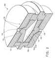
- the sample holder comprises an upstream manifold 151 and a downstream manifold 158 that together define an internal chamber 153.
- upstream and downstream are used for convenience, it should be noted here that there is no requirement that the apparatus be oriented as shown in the figures.
- a sample of the material to be tested can be placed in the holder so that the internal chamber 153 is effectively divided into an upper (upstream) portion 153a and a lower (downstream) portion 153b.
- the generated challenge particles first enter the upstream manifold 151 through an inlet 154.
- the flow of challenge particles is divided into a plurality of streams and then conducted to the edges of the sample through passages 155 so that the flow is distributed uniformly across the upstream surface of the test sample.
- the manifold also contains a star-shaped element 170 as generally depicted in Fig 3.
- the star-shaped element is constructed so that the passages 155 extend to the inner apexes 171 of the element. This provides for a uniform outward flow path of the mixture.
- Six passages 155 are provided but not all are shown in Fig. 3. However, any number of such passages can be used that provides the advantages noted above.
- a small fraction (about 300 cubic centimete-rs) of the challenge particles is extracted from the upper portion 153a through passage 156.
- the challenge particles are transported to and then counted in the Challenge Condensation Particle Counter (CCPC) 40, which provides continuous monitoring to establish a base line particle count.
- the CCPC 40 has a small internal pump (not shown) that draws in the mixture.
- the downstream manifold 158 is identical in structure to the upstream manifold, except there is a difference in the function. Depending on the barrier property of the sample, some portion of the challenge particles passes through the sample into lower portion 153b.
- a gas from supply 60 enters manifold 158 through inlet 159 and is distributed through passages 160 to portion 153b. While any gas can be used, air is satisfactory and is of course not expensive as nitrogen, for example, which is used in supply 15. This flow of air is referred to as sweep air because it picks up and transports the challenge particles through passage 161. This leads to FCPC 95, which measures the amount of challenge particles that passed through the sample.
- the manifold 158 is identical to manifold 151, therefore it also contains a structurally identical star-shaped element, but its function is primarily to provide uniform flow of sweep air so that all of the challenge particles are collected.
- FCPC 95 operates at a constant flow rate of 1.00 1/min using an external vacuum source 100 and an internal critical orifice, which is not shown.
- the driving force across the sample is primarily provided by the air demand of FCPC 95 at a constant 1 l/min and is partially provided by HEPA air source 60.
- a manometer 55 is connected to sample holder 150 to measure the pressure differential across the sample thereby providing an accurate measure of the flow rate relative to the baseline.
- the source 60 that provides air to the downstream side of the sample may be used to adjust the flow of particles in the system.
- the air passes through HEPA filter 70 before entering the downstream side of holder 150.
- HEPA High Efficiency Particle Attenuation
- the HEPA filters 70,80,90 keep the air flow throughout the system free of foreign particles that could affect the accuracy.
- HEPA filters 80,90 provide vents for excess aerosol to escape or a way for clean air to enter the system as necessary to prevent damage to the instruments.
- the particles are delivered to the FCPC 95 within the same time, irrespective of the flow rate through the sample.
- One advantage of this is allowing for relatively easy development of computer software to automate the testing procedure.
- the generator, the monitor, the classifier, the pressure regulator, the manometer, the challenge particle counter, and the filtered particle counter are all adapted for interfacing with a computer for process control and data collection.
- Orifices such as 85 are essentially very small holes, typically 50 to 100 micrometers in diameter, in a sheet of metal, usually brass. They are sized so that at flow rates greater than 0.5 standard liter per minute, the air flow reaches sonic velocity. This renders the airflow relatively insensitive to fluctuation within the chamber of the sample holder 150 or in other components. This insensitivity allows the flow rate to be kept constant over long periods of time, which is required when adjusting the flow of challenge particles through the sample to near zero by matching the demand of FCPC 95.
- This flow of sweep air can be varied from 0 to 1.0 l/min., which results in a flow across the sample of 1.0 to 0 l/min., respectively. This shows that the maximum flow through the sample of 1.00 l/min is achieved when the air supply 60 is turned off.
- the flow through the sample is the difference in demand between FCPC 95 and the HEPA air supply through critical orifice 85.
- FCPC 95 There may be excess air that is not required by FCPC 95 and this excess air can be vented through HEPA filter 90 and water trap 92. This can serve as an emergency release to prevent damage to the instrumentation and also provides a visual indication that something may be wrong in the system; a pinched hose, for example.
- Figure 4 shows in graph form that the preferred embodiment provides data at flow rates at least as low as those achieved when microbial agents are used.
- the graph shows that irrespective of the size of the aerosol oil droplet used in the preferred embodiment the ability to generate data at low flow rates is maintained.
- this limitation of conventional systems is primarily due to their inability to separate flow through the test sample from flow through the particle counter.
- the ability to separate the flow allows the subject invention to evaluate barrier properties at flow rates approaching zero. This is significant because at higher flow rates the primary mechanism of particle removal is that the particles impact the fibers of the subject material.
- Brownian movement and electrostatic attraction removes the particles. This phenomenon increases in importance as the residence time of a particle within a material increases.
- TYVEK® a registered trademark of E. I. Du Pont de Nemours and Company, Wilmington, Delaware (DuPont).
- TYVEK® a registered trademark of E. I. Du Pont de Nemours and Company, Wilmington, Delaware (DuPont).
- TYVEK® a registered trademark of E. I. Du Pont de Nemours and Company, Wilmington, Delaware (DuPont).
- the advantages of TYVEK® were not well appreciated because it has an electric charge and electrostatic attraction is an important mechanism at low flow rates.
- the preferred embodiment will be helpful in demonstrating the advantages of TYVEK® in medical products, protective apparel, desiccant packaging, filtration and other applications.
Landscapes
- Chemical & Material Sciences (AREA)
- Physics & Mathematics (AREA)
- Analytical Chemistry (AREA)
- Dispersion Chemistry (AREA)
- Health & Medical Sciences (AREA)
- Life Sciences & Earth Sciences (AREA)
- Biochemistry (AREA)
- General Health & Medical Sciences (AREA)
- General Physics & Mathematics (AREA)
- Immunology (AREA)
- Pathology (AREA)
- Fluid Mechanics (AREA)
- Sampling And Sample Adjustment (AREA)
- Investigating Or Analysing Biological Materials (AREA)
- Separation Using Semi-Permeable Membranes (AREA)
Abstract
Description
A method for measuring barrier properties of a material comprising the steps of:
an apparatus for measuring barrier properties of a material comprising:
Claims (10)
- A method for measuring barrier properties of a material comprising the steps of:a) positioning a sample of the material in a holding means (150) comprising a chamber wherein the material divides the chamber into a first portion (153a) and a second portion (153b) ;b) generating aerosol particles;c) generating a first gas for mixing with the aerosol;d) mixing the first gas and the aerosol particles;e) introducing the mixture of the aerosol particles and the first gas into the first portion (153a) and wherein some percentage of the aerosol particles pass through the sample from the first portion (153a) to the second portion (153b) ;f) extracting from the first portion (153a) a small amount of the mixture that does not pass through the sample,g) counting the aerosol particles from (f) in a first particle counter (40),h) introducing a second gas through a predetermined-sized orifice into the second portion (153b) to sweep particles that have passed through the sample;i) extracting from the second portion (153b) the mixture that passed through the sample,j) counting the aerosol particles from (i) in a second particle counter (95),k) comparing the number of aerosol particles determined in (g) to the number of aerosol particles determined in (j).
- The method of claim 1, wherein the aerosol particles have a size in the range of 0.03 micrometers to 7 micrometers.
- The method of claim 1 or 2, wherein the flow rate through the material is less than 1 liter per minute.
- The method of claim 3, wherein the flow rate approaches zero.
- The method of any preceding claim, wherein the flow rates in extracting steps (f) and (i) are independent of the flow rates of introducing steps (g) and (j).
- An apparatus for measuring barrier properties of a sample of material comprising:an aerosol particle generator (20) ;means (15) for providing a first gas,means for mixing the aerosol particles and the first gas;means for transporting the first gas and aerosol particle mixture;a sample holder (150) comprising a chamber for positioning the sample wherein the sample divides the chamber into a first portion (153a) and a second portion (153b), the first portion (153a) having an inlet and at least one outlet (156), and the second portion (153b) having an inlet and at least one outlet;means for introducing the first gas and aerosol particle mixture into the first portion (153a) through the first inlet ;means for introducing a gas into the second portion (153b) through the second inlet, and wherein, in use, the gas and aerosol particle mixture enters the first portion (153a) through the first inlet and a first percentage of the aerosol particles exits the first portion (153a) through the first outlet (156) into a first counting means (40) and a second percentage of the gas and aerosol particle mixture passes through the material into the second portion (153b) and exits the second portion (153b) through the second outlet into a second counting means (95), andmeans for comparing the aerosol particles counted in the first counting means (40) to the aerosol particles counted in the second counting means (95).
- The apparatus of claim 6, comprising means (55) for measuring the pressure differential between the first portion (153a) and the second portion (153b).
- The apparatus of claim 6 or 7, comprising means for classifying the aerosol particles in the size range of 0.03 micrometer to 0.8 micrometers.
- The apparatus of claim 6, 7 or 8, wherein the flow rate through the first counting means (40) and the flow rate through the second counting means (95) are independent of the flow through the material.
- The apparatus of any of claims 6-9, wherein the flow of the gas through the sample holder (150) has a separate path from the flow of aerosol particles through the first counting means (40) and second counting means (95).
Applications Claiming Priority (2)
| Application Number | Priority Date | Filing Date | Title |
|---|---|---|---|
| US489007 | 2000-02-04 | ||
| US09/498,007 US6532797B1 (en) | 2000-02-04 | 2000-02-04 | Barrier test apparatus and method |
Publications (2)
| Publication Number | Publication Date |
|---|---|
| EP1124126A2 true EP1124126A2 (en) | 2001-08-16 |
| EP1124126A3 EP1124126A3 (en) | 2003-10-29 |
Family
ID=23979234
Family Applications (1)
| Application Number | Title | Priority Date | Filing Date |
|---|---|---|---|
| EP01300941A Withdrawn EP1124126A3 (en) | 2000-02-04 | 2001-02-02 | Barrier test apparatus and method |
Country Status (2)
| Country | Link |
|---|---|
| US (2) | US6532797B1 (en) |
| EP (1) | EP1124126A3 (en) |
Families Citing this family (18)
| Publication number | Priority date | Publication date | Assignee | Title |
|---|---|---|---|---|
| US6532797B1 (en) * | 2000-02-04 | 2003-03-18 | E. I. Du Pont De Nemours And Company | Barrier test apparatus and method |
| US6910386B1 (en) | 2004-01-20 | 2005-06-28 | The Boeing Company | Method for testing flow characteristics of sealing materials |
| US7178384B2 (en) * | 2004-02-04 | 2007-02-20 | General Atomics | Method and apparatus for measuring ultralow permeation |
| US7257990B2 (en) * | 2005-04-25 | 2007-08-21 | General Atomics | Accelerated ultralow moisture permeation measurement |
| DE102007015584A1 (en) * | 2007-03-29 | 2008-10-02 | Maja-Maschinenfabrik Hermann Schill Gmbh & Co. Kg | Device and method for disinfecting ice machines, ice silos and / or channels for transporting ice |
| CN101809427B (en) * | 2007-09-28 | 2013-09-04 | 株式会社爱发科 | Device for measuring steam permeability, and method for the device |
| CN101701897B (en) * | 2009-10-22 | 2012-05-09 | 清华大学 | Filter material counting efficiency detection system and detection method based on quasi-monodisperse aerosol |
| US9266068B2 (en) | 2010-11-08 | 2016-02-23 | American Air Filter Company, Inc. | Aerosol generator for EPTFE filter testing and method of use |
| MY166510A (en) * | 2010-11-08 | 2018-07-05 | Aaf Mcquay Inc D/B/A Aaf Int | ePTFE Filter for Aseptic Pharmaceutical Use and Method of Using |
| CN102183444B (en) * | 2011-01-27 | 2013-09-25 | 中国商用飞机有限责任公司 | Device and method for testing gas permeability in inner direction of paving layer surface |
| CN102141504B (en) * | 2011-01-27 | 2013-06-12 | 中国商用飞机有限责任公司 | Testing device and method for testing gas penetration rate in thickness direction of overlay |
| CN103331710A (en) * | 2013-05-30 | 2013-10-02 | 苏州华达仪器设备有限公司 | Special fixture for filter material |
| CN104297423B (en) * | 2014-09-23 | 2015-12-02 | 京东方科技集团股份有限公司 | Pick-up unit and detection method |
| CN108931469A (en) * | 2017-05-25 | 2018-12-04 | 华为技术有限公司 | Dust-proof test equipment and dust-proof test method |
| CN111735750B (en) * | 2020-07-31 | 2020-11-17 | 北京核信锐视安全技术有限公司 | Device and method for detecting purification efficiency of aerosol protective equipment |
| US20220347497A1 (en) * | 2021-04-28 | 2022-11-03 | Ford Global Technologies, Llc | Methods of assembling personal air purifying respirators |
| CN113008763B (en) * | 2021-05-26 | 2021-08-13 | 北京力耘柯创医学研究院 | Method for detecting barrier property of soft infusion bag |
| EP4553480A1 (en) * | 2023-11-09 | 2025-05-14 | Volvo Car Corporation | Assembly and method for testing a cabin air quality component of a vehicle |
Family Cites Families (11)
| Publication number | Priority date | Publication date | Assignee | Title |
|---|---|---|---|---|
| US3286509A (en) * | 1964-09-22 | 1966-11-22 | St Regis Paper Co | Apparatus for measuring water vapor permeability |
| US3604246A (en) * | 1965-09-14 | 1971-09-14 | Minnesota Mining & Mfg | Permeability testing apparatus and method |
| GB1387408A (en) * | 1971-11-03 | 1975-03-19 | Atomic Energy Authority Uk | Testing of filters |
| US4619136A (en) * | 1985-07-03 | 1986-10-28 | The United States Of America As Represented By The United States Department Of Energy | Apparatus for measuring the decontamination factor of a multiple filter air-cleaning system |
| DE3641716A1 (en) * | 1986-12-06 | 1988-06-16 | Palas Gmbh | METHOD AND DEVICE FOR EXAMINING A PARTICLE-CONTAINING FLOW |
| US5203201A (en) * | 1991-12-20 | 1993-04-20 | Donaldson Company, Inc. | On-line web filtration efficiency test method |
| US5390539A (en) * | 1992-09-25 | 1995-02-21 | Modern Controls, Inc. | Device for measuring the permeability of a membrane to water vapor |
| US5412975A (en) * | 1993-11-12 | 1995-05-09 | The Regents Of The University Of California | Universal inlet for airborne-particle size-selective sampling |
| KR100213437B1 (en) * | 1997-04-17 | 1999-08-02 | 윤종용 | The testing method and filtering efficiency testing apparatus of glass fibres |
| US5817924A (en) * | 1998-01-21 | 1998-10-06 | Modern Controls, Inc. | Method and apparatus for measuring oxygen transmission through contact lenses |
| US6532797B1 (en) * | 2000-02-04 | 2003-03-18 | E. I. Du Pont De Nemours And Company | Barrier test apparatus and method |
-
2000
- 2000-02-04 US US09/498,007 patent/US6532797B1/en not_active Expired - Fee Related
-
2001
- 2001-02-02 EP EP01300941A patent/EP1124126A3/en not_active Withdrawn
-
2003
- 2003-02-21 US US10/371,302 patent/US6688160B2/en not_active Expired - Fee Related
Also Published As
| Publication number | Publication date |
|---|---|
| EP1124126A3 (en) | 2003-10-29 |
| US6688160B2 (en) | 2004-02-10 |
| US6532797B1 (en) | 2003-03-18 |
| US20030150255A1 (en) | 2003-08-14 |
Similar Documents
| Publication | Publication Date | Title |
|---|---|---|
| US6532797B1 (en) | Barrier test apparatus and method | |
| Lee et al. | On the minimum efficiency and the most penetrating particle size for fibrous filters | |
| US6125845A (en) | Respirator fit-testing with size selected aerosol | |
| Furuuchi et al. | Development and performance evaluation of air sampler with inertial filter for nanoparticle sampling | |
| US8689648B1 (en) | Compact aerosol sampler | |
| US8192523B1 (en) | Device and method for separating and increasing the concentration of charged particles in a sampled aerosol | |
| US9631222B2 (en) | Filter and blower geometry for particle sampler | |
| US20130220034A1 (en) | Personal nanoparticle respiratory depositions sampler and methods of using the same | |
| Furuuchi et al. | Development of a personal sampler for evaluating exposure to ultrafine particles | |
| US4382378A (en) | Method for testing filtration efficiency | |
| US20130141722A1 (en) | System and method for analyzing pore sizes of substrates | |
| Jensen et al. | Industrial hygiene | |
| Aitken et al. | Application of porous foams as size selectors for biologically relevant samplers | |
| Maus et al. | Determination of the fractional efficiencies of fibrous filter media by optical in situ measurements | |
| Jamriska et al. | Investigation of the filtration efficiency of HEPA and ULPA filters in submicron particle size range | |
| Li et al. | Aerosol aspiration efficiency of blunt and thin-walled samplers at different wind orientations | |
| Bahloul et al. | Development of a procedure to measure the performance of ventilation filters for nanoparticles | |
| Payne et al. | Evaluation of various face covering filter materials using particles classified by aerodynamic diameter up to 5 micrometres | |
| Dittler et al. | The influence of conditioning and regeneration on the separation behaviour of rigid surface filters for the separation of particles from gases | |
| Sharma | Penetration, pressure drop, and wickering characteristics of NIOSH certified P-100 and P95 filters under heavy DOP loading | |
| Robert et al. | Comparative study of filtration parameters depending on the nature of the filter material | |
| Halvorsen | Fit testing using size-selected aerosol | |
| Gentry et al. | Measurement of collection efficiency of amosite fibers | |
| Beamer et al. | In-Depth Survey Report: Evaluation of the Ventilation and Filtration System and Biohazard Detection System for the Automated Facer Canceller System at United States Postal Service, Cleveland Processing and Distribution Center, Cleveland, Ohio | |
| Sullivan et al. | Fluorometric method for determining the efficiency of spun-glass air filtration media |
Legal Events
| Date | Code | Title | Description |
|---|---|---|---|
| PUAI | Public reference made under article 153(3) epc to a published international application that has entered the european phase |
Free format text: ORIGINAL CODE: 0009012 |
|
| AK | Designated contracting states |
Kind code of ref document: A2 Designated state(s): AT BE CH CY DE DK ES FI FR GB GR IE IT LI LU MC NL PT SE TR |
|
| AX | Request for extension of the european patent |
Free format text: AL;LT;LV;MK;RO;SI |
|
| PUAL | Search report despatched |
Free format text: ORIGINAL CODE: 0009013 |
|
| AK | Designated contracting states |
Kind code of ref document: A3 Designated state(s): AT BE CH CY DE DK ES FI FR GB GR IE IT LI LU MC NL PT SE TR |
|
| AX | Request for extension of the european patent |
Extension state: AL LT LV MK RO SI |
|
| 17P | Request for examination filed |
Effective date: 20040301 |
|
| AKX | Designation fees paid |
Designated state(s): DE FR GB |
|
| 17Q | First examination report despatched |
Effective date: 20040623 |
|
| STAA | Information on the status of an ep patent application or granted ep patent |
Free format text: STATUS: THE APPLICATION IS DEEMED TO BE WITHDRAWN |
|
| 18D | Application deemed to be withdrawn |
Effective date: 20060408 |