EP1124005B1 - Pollution prevention method for a canvas used in a paper machine - Google Patents
Pollution prevention method for a canvas used in a paper machine Download PDFInfo
- Publication number
- EP1124005B1 EP1124005B1 EP99943344.4A EP99943344A EP1124005B1 EP 1124005 B1 EP1124005 B1 EP 1124005B1 EP 99943344 A EP99943344 A EP 99943344A EP 1124005 B1 EP1124005 B1 EP 1124005B1
- Authority
- EP
- European Patent Office
- Prior art keywords
- canvas
- silicone oil
- paper
- treatment agent
- paper strip
- Prior art date
- Legal status (The legal status is an assumption and is not a legal conclusion. Google has not performed a legal analysis and makes no representation as to the accuracy of the status listed.)
- Expired - Lifetime
Links
- 238000000034 method Methods 0.000 title claims description 31
- 230000002265 prevention Effects 0.000 title description 2
- 229920002545 silicone oil Polymers 0.000 claims description 119
- 238000005507 spraying Methods 0.000 claims description 18
- XLYOFNOQVPJJNP-UHFFFAOYSA-N water Substances O XLYOFNOQVPJJNP-UHFFFAOYSA-N 0.000 claims description 17
- 238000011109 contamination Methods 0.000 claims description 13
- 238000001035 drying Methods 0.000 claims description 13
- 238000012546 transfer Methods 0.000 claims description 10
- 238000003825 pressing Methods 0.000 claims description 7
- 239000004094 surface-active agent Substances 0.000 claims description 6
- 239000012466 permeate Substances 0.000 claims description 4
- 239000012756 surface treatment agent Substances 0.000 description 53
- 239000007921 spray Substances 0.000 description 41
- 208000018747 cerebellar ataxia with neuropathy and bilateral vestibular areflexia syndrome Diseases 0.000 description 33
- 238000012360 testing method Methods 0.000 description 23
- 239000000126 substance Substances 0.000 description 18
- 239000000356 contaminant Substances 0.000 description 15
- 230000000052 comparative effect Effects 0.000 description 8
- 230000000694 effects Effects 0.000 description 8
- 230000003373 anti-fouling effect Effects 0.000 description 7
- 239000000463 material Substances 0.000 description 6
- 230000004048 modification Effects 0.000 description 6
- 238000012986 modification Methods 0.000 description 6
- 229920001296 polysiloxane Polymers 0.000 description 5
- 230000008569 process Effects 0.000 description 5
- 239000000654 additive Substances 0.000 description 4
- 230000003247 decreasing effect Effects 0.000 description 4
- 238000007865 diluting Methods 0.000 description 4
- 239000000047 product Substances 0.000 description 4
- 230000000996 additive effect Effects 0.000 description 3
- 239000000853 adhesive Substances 0.000 description 3
- 230000001070 adhesive effect Effects 0.000 description 3
- 239000007864 aqueous solution Substances 0.000 description 3
- 238000010790 dilution Methods 0.000 description 3
- 239000012895 dilution Substances 0.000 description 3
- 238000005516 engineering process Methods 0.000 description 3
- 239000004744 fabric Substances 0.000 description 3
- 230000005484 gravity Effects 0.000 description 3
- 238000010438 heat treatment Methods 0.000 description 3
- 230000009467 reduction Effects 0.000 description 3
- 230000002829 reductive effect Effects 0.000 description 3
- 238000009825 accumulation Methods 0.000 description 2
- 239000003795 chemical substances by application Substances 0.000 description 2
- 238000010276 construction Methods 0.000 description 2
- -1 for example Substances 0.000 description 2
- 239000000203 mixture Substances 0.000 description 2
- 239000000843 powder Substances 0.000 description 2
- 238000007639 printing Methods 0.000 description 2
- 239000005871 repellent Substances 0.000 description 2
- 239000011347 resin Substances 0.000 description 2
- 229920005989 resin Polymers 0.000 description 2
- 239000004925 Acrylic resin Substances 0.000 description 1
- 239000004593 Epoxy Substances 0.000 description 1
- VGGSQFUCUMXWEO-UHFFFAOYSA-N Ethene Chemical compound C=C VGGSQFUCUMXWEO-UHFFFAOYSA-N 0.000 description 1
- 239000005977 Ethylene Substances 0.000 description 1
- 229920001410 Microfiber Polymers 0.000 description 1
- 239000004809 Teflon Substances 0.000 description 1
- 229920006362 Teflon® Polymers 0.000 description 1
- 239000002390 adhesive tape Substances 0.000 description 1
- 230000002411 adverse Effects 0.000 description 1
- 229920013822 aminosilicone Polymers 0.000 description 1
- 230000008901 benefit Effects 0.000 description 1
- 230000015572 biosynthetic process Effects 0.000 description 1
- 150000001768 cations Chemical class 0.000 description 1
- 230000008859 change Effects 0.000 description 1
- 239000000470 constituent Substances 0.000 description 1
- 238000007796 conventional method Methods 0.000 description 1
- 230000002542 deteriorative effect Effects 0.000 description 1
- 238000011161 development Methods 0.000 description 1
- 235000014113 dietary fatty acids Nutrition 0.000 description 1
- 125000004177 diethyl group Chemical group [H]C([H])([H])C([H])([H])* 0.000 description 1
- 239000006185 dispersion Substances 0.000 description 1
- 238000004945 emulsification Methods 0.000 description 1
- 238000001704 evaporation Methods 0.000 description 1
- 230000008020 evaporation Effects 0.000 description 1
- 229930195729 fatty acid Natural products 0.000 description 1
- 239000000194 fatty acid Substances 0.000 description 1
- 150000004665 fatty acids Chemical class 0.000 description 1
- 239000000835 fiber Substances 0.000 description 1
- 210000003128 head Anatomy 0.000 description 1
- 239000012943 hotmelt Substances 0.000 description 1
- 230000002401 inhibitory effect Effects 0.000 description 1
- 239000000976 ink Substances 0.000 description 1
- 238000004519 manufacturing process Methods 0.000 description 1
- 239000003658 microfiber Substances 0.000 description 1
- 231100000989 no adverse effect Toxicity 0.000 description 1
- 239000003973 paint Substances 0.000 description 1
- 239000010893 paper waste Substances 0.000 description 1
- 230000002093 peripheral effect Effects 0.000 description 1
- 230000035699 permeability Effects 0.000 description 1
- 229920003216 poly(methylphenylsiloxane) Polymers 0.000 description 1
- 229920000728 polyester Polymers 0.000 description 1
- 239000011148 porous material Substances 0.000 description 1
- 239000002994 raw material Substances 0.000 description 1
- 230000003014 reinforcing effect Effects 0.000 description 1
- 238000004381 surface treatment Methods 0.000 description 1
- 229920002994 synthetic fiber Polymers 0.000 description 1
- 239000012209 synthetic fiber Substances 0.000 description 1
- 239000002759 woven fabric Substances 0.000 description 1
Images



Classifications
-
- D—TEXTILES; PAPER
- D21—PAPER-MAKING; PRODUCTION OF CELLULOSE
- D21F—PAPER-MAKING MACHINES; METHODS OF PRODUCING PAPER THEREON
- D21F1/00—Wet end of machines for making continuous webs of paper
- D21F1/32—Washing wire-cloths or felts
-
- D—TEXTILES; PAPER
- D21—PAPER-MAKING; PRODUCTION OF CELLULOSE
- D21F—PAPER-MAKING MACHINES; METHODS OF PRODUCING PAPER THEREON
- D21F1/00—Wet end of machines for making continuous webs of paper
- D21F1/30—Protecting wire-cloths from mechanical damage
-
- D—TEXTILES; PAPER
- D21—PAPER-MAKING; PRODUCTION OF CELLULOSE
- D21H—PULP COMPOSITIONS; PREPARATION THEREOF NOT COVERED BY SUBCLASSES D21C OR D21D; IMPREGNATING OR COATING OF PAPER; TREATMENT OF FINISHED PAPER NOT COVERED BY CLASS B31 OR SUBCLASS D21G; PAPER NOT OTHERWISE PROVIDED FOR
- D21H21/00—Non-fibrous material added to the pulp, characterised by its function, form or properties; Paper-impregnating or coating material, characterised by its function, form or properties
- D21H21/02—Agents for preventing deposition on the paper mill equipment, e.g. pitch or slime control
-
- Y—GENERAL TAGGING OF NEW TECHNOLOGICAL DEVELOPMENTS; GENERAL TAGGING OF CROSS-SECTIONAL TECHNOLOGIES SPANNING OVER SEVERAL SECTIONS OF THE IPC; TECHNICAL SUBJECTS COVERED BY FORMER USPC CROSS-REFERENCE ART COLLECTIONS [XRACs] AND DIGESTS
- Y10—TECHNICAL SUBJECTS COVERED BY FORMER USPC
- Y10S—TECHNICAL SUBJECTS COVERED BY FORMER USPC CROSS-REFERENCE ART COLLECTIONS [XRACs] AND DIGESTS
- Y10S162/00—Paper making and fiber liberation
- Y10S162/04—Pitch control
Definitions
- the present invention relates to a method of preventing contamination of a canvas used in conjunction with dryers of a paper machine.
- the paper machine is equipped with a plurality of dryers used for drying, and the dryers have a construction such that a heating medium such as steam and the like are contained therein for heating from inside of the dryers.
- Moist paper undried as yet is fed continuously to the dryers of the paper machine.
- the wet paper gives off moisture contained therein by absorbing heat from the surface of the dryers when pressed by the canvas.
- the canvas is normally formed of material flexible and porous, for example, woven fabric, felt (unwoven fabric), knitted fabric, and the like.
- An enlarged view of the surface of the canvas shows that a multitude of fine pores (so-called eyes of the canvas) are formed on the surface thereof between threads making up the canvas.
- Moisture contained in the wet paper is heated by the dryers at high temperatures, and dispersed through the eyes of the canvas.
- paper contains various substances, for example, pitch / tar component contained in pulp stock itself, hotmelt, ink and microfibers originating from waste paper stock, various additive chemicals for reinforcing strength and whiteness of paper, and inclusions (foreign matter) such as paint, and so forth.
- inclusions foreign matter
- Such inclusions having tackiness will be deposited on the surface of the canvas when the wet paper is pressed hard against the surface of the dryers by the canvas, turning into contaminant (the source of contamination).
- the longer service life means that there will be an increase in accumulation of the contaminant to that extent.
- Parts of the contaminant accumulated on the canvas are then transferred from the surface of the canvas to a portion of a paper strip, newly fed, resulting in contamination of product paper.
- the contaminant having strong tackiness is also accumulated on an out-roll serving as a guide-roll for the canvas and turned into large lumps.
- the wet paper When parts of such lumps are peeled off, and adhere to the surface of the wet paper, the wet paper will be provided with additional tensile force due to the effect of the tackiness of the contaminant at the time of the dryers coming in contact with the wet paper, creating a cause for breaks of the wet paper.
- the paper machine has been faced with major technical problems in that various inclusions contained in the wet paper are adhered to the canvas, and accumulated thereon along with the operation of the paper machine, whereupon the eyes of the canvas are clogged, thereby inhibiting evaporation of moisture, and resulting in poor drying efficiency, and also in that the contaminant accumulated on the canvas as well as the out-roll causes parts of the paper strip, newly fed, to be contaminated as well or create a cause for breaks of the paper strip being processed.
- JP-A-07-292 382 discloses a stain-proofing agent containing silicone oil for paper-making drier process in which the stain-proofing agent is sprayed on a canvas endless loop which supports paper as it dries; and GB-A-2 284 833 discloses paper-making machinery which employs a roller applicator to apply a thin hyrdrophobic film of silicone to the surface of the fabric which is in contact with the paper sheet.
- the present invention has been developed in an attempt to solve various problems described in the foregoing.
- a method of preventing contamination of a canvas running in a closed loop and having an outer surface for pressing a paper strip against the surface of drum-dryers used for drying the paper strip in a paper machine whereby a silicone oil is continuously sprayed, at a supply rate of 0.1 to 200 mg/m 2 per min, onto the surface of a canvas out-roll disposed on the outer side of the canvas for guiding the canvas, in a stage of operation prior to the paper strip being pressed into contact with the canvas as well as the drum-dryers, while the paper strip is being fed by operation of the paper machine.
- a silicone oil emulsified with a surfactant is used for supplying the silicone oil.
- the silicone oil is diluted with water before being sprayed.
- the silicone oil is diluted with water, heated to a temperature in the range of 50 to 80°C immediately before spraying
- the method comprises the following steps 1) to 5): 1) a silicone oil supply step for supplying a silicone oil at a supply rate of 0.1 to 200 mg/m 2 per min to the surface of the out-roll disposed on the outer side of the canvas for guiding the canvas; 2) a silicone oil shifting step for shifting the silicone oil from the surface of the out-roll to the canvas outer surface; 3) a silicone oil permeation and adhesion step for causing the silicone oil to permeate through the canvas and adhere to the outer surface thereof under heat and pressure; 4) a silicone oil transfer step for pressing the paper strip against the canvas outer surface, causing the silicone oil to be transferred to the paper strip; and 5) a silicone oil replenishment step for replenishing the silicone oil on the canvas outer surface depleted by said transfer.
- the inventors have carried out intense studies on the subjects described, and discovered as a result that silicone can be caused to adhere to the surface of the canvas to an extent not to cause the eyes of the canvas to be clogged by continuously supplying silicone oil to the canvas without interruption.
- the inventors have succeeded in the development of the present invention on the basis of this fact.
- the silicone oil By continuously supplying the silicone oil by a predetermined amount onto the surface of the canvas, the silicone oil is adhered to the surface of the canvas.
- the silicone oil permeates through the canvas and is adhered thereto.
- the silicone oil is gradually transferred to the paper strip and depleted but, on the other hand, since the canvas is continuously supplied with the silicone oil without interruption, the canvas remains in a condition with newly supplied silicone adhered thereto after depleted portions of the silicone oil is replenished.
- Fig. 1 shows a paper machine equipped with multiple drum-dryers, comprising broadly a wire part A, a press part B, and a dry part C.
- feed stock (pulp and so forth) is fed from a flow spreader head box onto a Fourdrinier wire table A1 evenly so as to be formed into a sheet-like shape.
- a paper strip W formed in a sheet-like shape will have the moisture thereof reduced to the order of 80% while passing on the Fourdrinier wire table A1, and then be transferred to the press part B.
- the paper strip W is squeezed from both above and below by a pressing roller B1, an endless belt B2, and so forth.
- the paper strip W will have the moisture thereof reduced to the order of 50% while passing through the press part B, and thereafter, be transferred to the dry part (drying area) C.
- the greater part of humidity of the paper strip W will be given off, and the moisture thereof will be reduced to the order of 10%.
- the dry part C is provided with heated drum-dryers C1, canvases C2, C3 for pressing the paper strip against the drum-dryers, and canvas rollers C4 and so forth for guiding the canvases, so as to cause the paper strip W to give off the moisture thereof by the effect of heat.
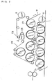
- Fig. 1 The paper machine shown in Fig. 1 comprises two dry parts, each consisting of a group of drum-dryers, and Fig. 2 is an enlarged view of one of the dry parts.
- the dry part C has a construction such that the canvases C2, C3, disposed on the upper level and the lower level, respectively, are caused to run by a plurality of the canvas rollers along paths in a given closed loop, respectively, so as to be pressed into contact with a plurality of the drum-dryers C1.
- the drum-dryers C1 in use are of a multiple type, and the plurality thereof are juxtaposed on the upper level as well as the lower level, respectively.
- the canvases C2 and C3 act to press the paper strip into contact with the respective drum-dryers, and run between the respective canvas rolls C4 in sequence.
- the inner canvas rolls C4 are disposed on the inner side of the canvases C2, C3, and out-rolls C5 are disposed on the outer side thereof.
- the out-rolls are normally set so as to be freely movable, enabling tension of the respective canvases in whole to be adjusted.
- the paper strip W (in fact, wet paper) is fed and transferred along a given path, while being pressed in contact with both the canvases and the drum-dryers.
- Drying of the paper strip W gradually proceeds as the paper strip W is pressed between the canvas and the drum-dryers at the upper level, and between the canvas and drum-dryers at the lower level, respectively.
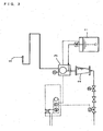
- a chemical spray unit used for spraying a chemical that is, the surface treatment agent, is shown in Fig. 3 .
- the surface treatment agent delivered from a chemical tank 1 is sprayed to the surface of the canvas through a spray nozzle S.
- Water may be taken in via a flow meter 2 as necessary, and mixed with the surface treatment agent through a mixer 3, so that water can be sprayed simultaneously through the spray nozzle S.
- a method of spraying onto the canvas may be selected in various ways by changing the type of the spray nozzle.
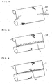
- Figs. 4 to 6 are schematic illustrations of modifications not forming part of the present invention showing various states in which the surface treatment agent is sprayed.
- Fig. 4 is a schematic illustration of a modification not forming part of the present invention showing a spraying state wherein a silicone oil is sprayed onto the surface of the canvas through fixed type spray nozzles of the chemical spray unit
- Fig. 5 a schematic illustration of a modification not forming part of the present invention showing same in the case of using the chemical spray unit provided with spray nozzles disposed lengthwise
- Fig. 6 a schematic illustration of a modification not forming part of the present invention showing same in the case of using the chemical spray unit provided with a movable spray nozzle.
- the surface treatment agent is sprayed onto the surface of the canvases through the spray nozzles set as shown in Figs. 4 to 6 , respectively, at the positions indicated by the letters X, Y, and so forth, respectively, in Fig. 2 .
- the surface treatment agent used in carrying out the invention is composed mainly of silicone oil.
- methylphenyl silicone oil diethyl silicone oil, denatured amino silicone oil, denatured epoxy silicone oil, denatured higher fatty acid silicone oil, and so forth are adopted for the silicone oil (silicone-based oil).
- the silicone oil (silicone-based oil), that is, the surface treatment agent, may preferably be emulsified by adding a surfactant thereto so as to lower viscosity thereof as well as to improve dispersion characteristic during spraying.
- the surfactant used for emulsification of the silicone oil may preferably be added in percentage corresponding to 15 to 70 wt. % of the silicone oil, and the surface treatment agent is normally prepared by diluting the silicone oil with water 4 to 15 times as much.
- the surface treatment agent is further diluted with water by a factor of 100 to 3000 in order to spray the surface treatment agent in a wider range on the canvases simultaneously.
- water used for dilution may preferably be heated to a temperature in the range of 50 to 80 DEG C to minimize a risk of the nozzles getting clogged with scum and slime.
- the surface treatment agent too is to be heated to a substantially equivalent temperature.
- the surface treatment agent containing the silicone oil is continuously supplied onto the surface of the canvases (a silicone oil supply step).
- the silicone oil supplied to the canvases is heated by conduction heat of the drum-dryers, and permeates through the canvases (a silicone oil permeation and adhesion step).
- the silicone oil makes ingress into the interior of the canvases from the surface thereof, and is closely adhered thereto.
- the silicone oil adhered to the surface of the canvases is continuously transferred by a predetermined amount to the paper strip as the canvases continue to be pressed against the paper strip (a silicone oil transfer step).
- any depleted portion of the silicone oil can be replenished quickly (a silicone oil replenishment step).
- the surface of the canvases is always in a condition where a suitable amount of the silicone oil contained in the surface treatment agent is present, enabling the canvases to withstand continuous operation satisfactorily.
- Fig. 7 is a schematic illustration showing how the surface of the canvases is treated with the surface treatment agent containing the silicone oil. The process of such treatment comprises the following steps.
- the silicone oil P is adhered to the surface of the canvas C2 (A).
- the silicone oil P is heated up by the drum-dryers, and makes ingress into the interior of the canvas C2 (B).
- the silicone oil P makes further ingress deeper into the interior of the canvas C2 (C).
- the silicone oil P is transferred to the paper strip W, undergoing natural depletion on the surface of the canvas C2 (D).
- the steps 1) to 3) described above are carried out by continuously supplying a new region of the surface of the canvas in motion with the surface treatment agent containing the silicone oil.
- an important point in carrying out the invention is an amount of the silicone oil to be supplied to the canvases at a time.
- the supply (spraying) of the silicone oil needs to be made so as to meet these two requirements.
- a supply rate of the silicone oil somewhat varies depending on the type of the canvas and quality of the paper strip, however, it is normally 0.1 to 200 mg / m 2 per min, preferably 1 to 100 mg / m 2 per min.
- the supply rate is less than 0.1 mg / m 2 per min, sufficient permeation of the silicone oil into the canvases does not occur while if the supply rate exceeds 200 mg / m 2 per min, dripping of the surface treatment agent containing the silicone oil occurs, causing clogging of the eyes of the canvases, oil stain on paper, or contamination of peripheral equipment.
- a test was carried out for a month, wherein a surface treatment agent was continuously sprayed onto the surface of a canvas through the nozzle of the chemical spray unit shown in Fig. 6 , and thereafter, the condition of the surface of the canvas at that point in time was observed.
- the surface treatment agent used in the test was an emulsified aqueous solution prepared by diluting a mixture composed of the silicone oil and a surfactant mixed at wt. ratio of 10 : 5 with water 6 times as much as the silicone oil (specific gravity at about 1.0 g / cc).
- a test was carried out for a month, wherein a surface treatment agent was continuously sprayed onto the surface of the canvas through the nozzle of the chemical spray unit shown in Fig. 5 , and thereafter, the surface condition of an outroll for the canvas at that point in time was observed.
- the surface treatment agent used in the test was an emulsified aqueous solution prepared by diluting the surface treatment agent used in the embodiment 1 with water heated to 60°C in quantity 200 times as much (specific gravity at about 1.0 g/ cc).
- breaks of paper occurred 8 times in the dry part during the test, representing a marked reduction in frequency of occurrence of the breaks in comparison with that experienced before application of the technology disclosed herein, which was 40 times per month.
- a test was carried out for a month, wherein a surface treatment agent was continuously sprayed onto the surface of the canvas through the nozzle of the chemical spray unit shown in Fig. 6 , and thereafter, the condition of the surface of the canvas at that point in time was observed.
- the surface treatment agent used in the test was an emulsified aqueous solution prepared by diluting a mixture composed of the silicone oil and the surfactant mixed at wt. ratio of 10 : 8 with water 14 times as much as the silicone oil (specific gravity at about 1.0 g / cc).
- breaks of paper occurred 6 times in the dry part during the test, representing a marked reduction in frequency of occurrence of the breaks in comparison with that experienced before application of the technology disclosed herein, which was 20 times per month.
- Test results showed that in the case of using water at room temperature, the nozzle was clogged up frequently (once a week or once every other week) while in the case of using water heated up, no clogging of the nozzle occurred at all, enabling efficient spraying to be carried out.
- Fig. 15 shows the result of such comparison.
- the method described hereinbefore relates to the method of supplying the surface treatment agent directly onto the surface of the canvas.
- This disclosure provides an alternative method, in accordance with the invention as claimed, of supplying the surface treatment agent indirectly onto the surface of the canvas other than the method of supplying the surface treatment agent directly onto the surface of the canvas.
- Fig. 8 shows a method of supplying a surface treatment agent indirectly onto the surface of the canvas by way of example, and particularly in this case, an example wherein the surface treatment agent is sprayed onto an outroll in a pulled-back position is shown.
- a surface treatment agent containing the silicone oil is sprayed onto the surface of the outroll through spray nozzles (fixed type) of the chemical spray unit.
- Fig. 9 is a view showing an example wherein the surface treatment agent is sprayed onto the surface of the outroll through a movable type spray nozzle of the chemical spray unit.
- Fig. 10 is a view showing an example wherein the surface treatment agent is sprayed onto the surface of the outroll using the chemical spray unit provided with spray nozzles disposed lengthwise.
- an advantage of preventing scattering of the surface treatment agent is gained by applying spraying to the outroll C5 disposed in a pulled-back position (position indicated by the letter Z in Fig. 2 ) because a narrow space formed between the top side and the underside of the outroll C5 can be isolated by a canvas C2.
- the silicone oil P is adhered to the surface of the outroll.
- the silicone oil P is shifted from the surface of the outroll to the canvas C2, and as a result, the silicone oil P is adhered to the surface of the canvas.
- a position where spraying is made is selectable optionally within the paper machine as long as the position will not interfere with the operation of the paper machine.
Landscapes
- Paper (AREA)
- Prevention Of Fouling (AREA)
- Materials Applied To Surfaces To Minimize Adherence Of Mist Or Water (AREA)
- Treatments For Attaching Organic Compounds To Fibrous Goods (AREA)
Description
- The present invention relates to a method of preventing contamination of a canvas used in conjunction with dryers of a paper machine.
- Paper has recently been put to numerous applications in an extensive range, and paper stock having functions never heard before has been developed up to date.
- As a result, paper produced by a paper machine has come to be diversified, and is numerous in type. As paper produced by a paper machine has to go through a drying process before turned into a product, the drying process occupies a very important position from the technical viewpoint.
- The paper machine is equipped with a plurality of dryers used for drying, and the dryers have a construction such that a heating medium such as steam and the like are contained therein for heating from inside of the dryers.
- Moist paper undried as yet is fed continuously to the dryers of the paper machine.
- It is a canvas as it is called that plays a role of pressing hard wet paper into contact with the surface of the dryers.
- The wet paper gives off moisture contained therein by absorbing heat from the surface of the dryers when pressed by the canvas.
- For this reason, the canvas is normally formed of material flexible and porous, for example, woven fabric, felt (unwoven fabric), knitted fabric, and the like.
- An enlarged view of the surface of the canvas shows that a multitude of fine pores (so-called eyes of the canvas) are formed on the surface thereof between threads making up the canvas.
- Moisture contained in the wet paper is heated by the dryers at high temperatures, and dispersed through the eyes of the canvas.
- Incidentally, paper contains various substances, for example, pitch / tar component contained in pulp stock itself, hotmelt, ink and microfibers originating from waste paper stock, various additive chemicals for reinforcing strength and whiteness of paper, and inclusions (foreign matter) such as paint, and so forth. Such inclusions having tackiness will be deposited on the surface of the canvas when the wet paper is pressed hard against the surface of the dryers by the canvas, turning into contaminant (the source of contamination).
- That is, the inclusions contained in paper undergo denaturization due to the effect of pressure and heat, and adhere to the surface of the canvas, causing the eyes of the canvas to be clogged.
- There has since been a shift in raw material for the canvas from natural fiber to synthetic fiber with the result that the canvas has come to have a longer service life due to longer durability thereof.
- The longer service life means that there will be an increase in accumulation of the contaminant to that extent.
- Accordingly, after the operation of the paper machine for a long duration, there will occur fairly often a phenomenon wherein the eyes of the canvas get clogged with the contaminant.
- In recent times, addition of, for example, polyacrylic resin to paper has been in practice during a paper making process in order to reinforce paper strength and to improve a product yield, and particularly, in the case of an additive of a cation type being used, the additive is easily transferred to the canvas, and adheres thereto, causing the eyes of the canvas to be clogged.
- Once the clogging of the eyes of the canvas occurs, air permeability of the canvas deteriorates drastically, resulting in poor drying efficiency of paper.
- More specifically, sufficient moisture is normally emitted from the wet paper through the eyes of the canvas when the wet paper is pressed hard between the dryers and the canvas, however, once the clogging of the eyes of the canvas occurs, emitted moisture can not find its way out. In such a state, the drying efficiency deteriorates significantly.
- Parts of the contaminant accumulated on the canvas are then transferred from the surface of the canvas to a portion of a paper strip, newly fed, resulting in contamination of product paper.
- The contaminant having strong tackiness is also accumulated on an out-roll serving as a guide-roll for the canvas and turned into large lumps.
- When parts of such lumps are peeled off, and adhere to the surface of the wet paper, the wet paper will be provided with additional tensile force due to the effect of the tackiness of the contaminant at the time of the dryers coming in contact with the wet paper, creating a cause for breaks of the wet paper.
- For solving such problems as described above, countermeasures have been adopted wherein periodical cleanups of the canvas are carried out frequently or an interval between replacements of the canvas is rendered shorter. These countermeasures, however, have turned out to be expensive in terms of time and cost.
- Accordingly, there has been developed a method of preventing contamination of the canvas by applying surface treatment to the canvas.
- That is, it is a method whereby the surface of the canvas is treated with a water-repellent or oil-repellent resin, for example, ethylene resin tetrafluoride.
- Such treatment, however, will result in formation of regions where the eyes of the canvas are partially clogged, causing the drying efficiency to be deteriorated.
- Furthermore, such an anti-fouling treatment will be effective only in the initial stage of operation of the paper machine, and the effect of the treatment will decrease in several days (for example, in 5 to 6 days after the treatment is applied), so that a treated canvas then will not be different at all from the canvas untreated.
- As described in the foregoing, the paper machine has been faced with major technical problems in that various inclusions contained in the wet paper are adhered to the canvas, and accumulated thereon along with the operation of the paper machine, whereupon the eyes of the canvas are clogged, thereby inhibiting evaporation of moisture, and resulting in poor drying efficiency, and also in that the contaminant accumulated on the canvas as well as the out-roll causes parts of the paper strip, newly fed, to be contaminated as well or create a cause for breaks of the paper strip being processed.
-
JP-A-07-292 382 GB-A-2 284 833 - The present invention has been developed in an attempt to solve various problems described in the foregoing.
- According to the present invention, there is provided a method of preventing contamination of a canvas running in a closed loop and having an outer surface for pressing a paper strip against the surface of drum-dryers used for drying the paper strip in a paper machine, whereby a silicone oil is continuously sprayed, at a supply rate of 0.1 to 200 mg/m2 per min, onto the surface of a canvas out-roll disposed on the outer side of the canvas for guiding the canvas, in a stage of operation prior to the paper strip being pressed into contact with the canvas as well as the drum-dryers, while the paper strip is being fed by operation of the paper machine.
- In preferred embodiments, a silicone oil emulsified with a surfactant is used for supplying the silicone oil.
- In more preferred embodiments, the silicone oil is diluted with water before being sprayed.
- In yet more preferred embodiments, the silicone oil is diluted with water, heated to a temperature in the range of 50 to 80°C immediately before spraying
- In still further preferred embodiments, the method comprises the following steps 1) to 5): 1) a silicone oil supply step for supplying a silicone oil at a supply rate of 0.1 to 200 mg/m2 per min to the surface of the out-roll disposed on the outer side of the canvas for guiding the canvas; 2) a silicone oil shifting step for shifting the silicone oil from the surface of the out-roll to the canvas outer surface; 3) a silicone oil permeation and adhesion step for causing the silicone oil to permeate through the canvas and adhere to the outer surface thereof under heat and pressure; 4) a silicone oil transfer step for pressing the paper strip against the canvas outer surface, causing the silicone oil to be transferred to the paper strip; and 5) a silicone oil replenishment step for replenishing the silicone oil on the canvas outer surface depleted by said transfer.
- It is therefore an object of the invention to provide a method of preventing contamination of a canvas used in a paper machine, capable of not only maintaining the antifouling effect thereof at all times but also ensuring precise drying efficiency thereof.
- In this respect, the inventors have carried out intense studies on the subjects described, and discovered as a result that silicone can be caused to adhere to the surface of the canvas to an extent not to cause the eyes of the canvas to be clogged by continuously supplying silicone oil to the canvas without interruption. The inventors have succeeded in the development of the present invention on the basis of this fact.
- By continuously supplying the silicone oil by a predetermined amount onto the surface of the canvas, the silicone oil is adhered to the surface of the canvas.
- As the canvas and the paper strip are pressed into contact with each other, and subjected to heating by the dryers, the silicone oil permeates through the canvas and is adhered thereto.
- On one hand, the silicone oil is gradually transferred to the paper strip and depleted but, on the other hand, since the canvas is continuously supplied with the silicone oil without interruption, the canvas remains in a condition with newly supplied silicone adhered thereto after depleted portions of the silicone oil is replenished.
- Accordingly, various inclusions contained in the paper strip are prevented from adhering to the surface of the canvas.
- To enable a better understanding of the present invention, and to show how the same may be carried into effect, reference will now be made, by way of example only, to the accompanying drawings, in which:-
-
Fig. 1 is a schematic illustration showing a paper machine in whole, provided with a dry part having multiple drum-dryers; -
Fig. 2 is an enlarged view of the dry part shown inFig. 1 ; -
Fig. 3 is a schematic illustration showing a chemical spray unit used for spraying a surface treatment agent; -
Fig. 4 is a view showing a state of spraying the surface treatment agent onto a canvas of the paper machine through fixed type spray nozzles of the chemical spray unit which does not form part of the present invention; -
Fig. 5 is a view showing a state of spraying the surface treatment agent onto a canvas of the paper machine through spray nozzles disposed lengthwise, which does not form part of the present invention; -
Fig. 6 is a view showing a state of spraying the surface treatment agent onto a canvas of the paper machine through a movable type spray nozzle, which does not form part of the present invention; -
Fig. 7 is a schematic illustration showing the principle of silicone oil adhering to the surface of a canvas; -
Fig. 8 is a view showing a state of spraying the surface treatment agent onto the surface of an out-roll of the paper machine through the fixed type spray nozzles of the chemical spray unit; -
Fig. 9 is a view showing a state of spraying the surface treatment agent onto the surface of an out-roll of the paper machine through the movable type spray nozzle; -
Fig. 10 is a view showing a state of spraying the surface treatment agent onto the surface of an out-roll of the paper machine through the spray nozzles disposed lengthwise; -
Fig. 11 is a photograph showing the result of carrying out a first embodiment of a method not forming part of the claimed invention; -
Fig. 12 is a photograph showing the result of carrying out a second embodiment of a method not forming part of the claimed invention; -
Fig. 13 is a photograph showing the result of carrying out acomparative example method 1; -
Fig. 14 is a photograph showing the result of carrying out acomparative example method 2; and -
Fig. 15 is a photograph showing the result of carrying out acomparative example method 3. - First, an example of a paper machine to which the invention is applied is described.
-
Fig. 1 shows a paper machine equipped with multiple drum-dryers, comprising broadly a wire part A, a press part B, and a dry part C. - Operation of the paper machine is briefly described as follows.
- In the wire part A, feed stock (pulp and so forth) is fed from a flow spreader head box onto a Fourdrinier wire table A1 evenly so as to be formed into a sheet-like shape.
- A paper strip W formed in a sheet-like shape will have the moisture thereof reduced to the order of 80% while passing on the Fourdrinier wire table A1, and then be transferred to the press part B.
- In the press part B, the paper strip W is squeezed from both above and below by a pressing roller B1, an endless belt B2, and so forth.
- The paper strip W will have the moisture thereof reduced to the order of 50% while passing through the press part B, and thereafter, be transferred to the dry part (drying area) C.
- In the dry part C, the greater part of humidity of the paper strip W will be given off, and the moisture thereof will be reduced to the order of 10%.
- More specifically, the dry part C is provided with heated drum-dryers C1, canvases C2, C3 for pressing the paper strip against the drum-dryers, and canvas rollers C4 and so forth for guiding the canvases, so as to cause the paper strip W to give off the moisture thereof by the effect of heat.
- The paper machine shown in
Fig. 1 comprises two dry parts, each consisting of a group of drum-dryers, andFig. 2 is an enlarged view of one of the dry parts. - The dry part C has a construction such that the canvases C2, C3, disposed on the upper level and the lower level, respectively, are caused to run by a plurality of the canvas rollers along paths in a given closed loop, respectively, so as to be pressed into contact with a plurality of the drum-dryers C1.
- The drum-dryers C1 in use are of a multiple type, and the plurality thereof are juxtaposed on the upper level as well as the lower level, respectively.
- As described above, the canvases C2 and C3 act to press the paper strip into contact with the respective drum-dryers, and run between the respective canvas rolls C4 in sequence.
- As is evident from the figure, the inner canvas rolls C4 are disposed on the inner side of the canvases C2, C3, and out-rolls C5 are disposed on the outer side thereof.
- The out-rolls are normally set so as to be freely movable, enabling tension of the respective canvases in whole to be adjusted.
- Now, in the dry part C of the paper machine described above, the paper strip W (in fact, wet paper) is fed and transferred along a given path, while being pressed in contact with both the canvases and the drum-dryers.
- Drying of the paper strip W gradually proceeds as the paper strip W is pressed between the canvas and the drum-dryers at the upper level, and between the canvas and drum-dryers at the lower level, respectively.
- Now, for guidance, a chemical spray unit used for spraying a chemical, that is, the surface treatment agent, is shown in
Fig. 3 . - With the chemical spray unit, the surface treatment agent delivered from a
chemical tank 1 is sprayed to the surface of the canvas through a spray nozzle S. - Water may be taken in via a
flow meter 2 as necessary, and mixed with the surface treatment agent through amixer 3, so that water can be sprayed simultaneously through the spray nozzle S. - A method of spraying onto the canvas may be selected in various ways by changing the type of the spray nozzle.
-
Figs. 4 to 6 are schematic illustrations of modifications not forming part of the present invention showing various states in which the surface treatment agent is sprayed. -
Fig. 4 is a schematic illustration of a modification not forming part of the present invention showing a spraying state wherein a silicone oil is sprayed onto the surface of the canvas through fixed type spray nozzles of the chemical spray unit,Fig. 5 a schematic illustration of a modification not forming part of the present invention showing same in the case of using the chemical spray unit provided with spray nozzles disposed lengthwise, andFig. 6 a schematic illustration of a modification not forming part of the present invention showing same in the case of using the chemical spray unit provided with a movable spray nozzle. - For prevention of contamination of the canvases, the surface treatment agent is sprayed onto the surface of the canvases through the spray nozzles set as shown in
Figs. 4 to 6 , respectively, at the positions indicated by the letters X, Y, and so forth, respectively, inFig. 2 . - The surface treatment agent used in carrying out the invention is composed mainly of silicone oil.
- In this case, methylphenyl silicone oil, diethyl silicone oil, denatured amino silicone oil, denatured epoxy silicone oil, denatured higher fatty acid silicone oil, and so forth are adopted for the silicone oil (silicone-based oil).
- The silicone oil (silicone-based oil), that is, the surface treatment agent, may preferably be emulsified by adding a surfactant thereto so as to lower viscosity thereof as well as to improve dispersion characteristic during spraying.
- The surfactant used for emulsification of the silicone oil may preferably be added in percentage corresponding to 15 to 70 wt. % of the silicone oil, and the surface treatment agent is normally prepared by diluting the silicone oil with water 4 to 15 times as much.
- Needless to say, other additives may be further added thereto as necessary.
- There may be cases where the surface treatment agent is further diluted with water by a factor of 100 to 3000 in order to spray the surface treatment agent in a wider range on the canvases simultaneously.
- Further, water used for dilution may preferably be heated to a temperature in the range of 50 to 80 DEG C to minimize a risk of the nozzles getting clogged with scum and slime.
- Naturally, in this case, the surface treatment agent too is to be heated to a substantially equivalent temperature.
- Now, a series of steps for supplying the canvases with the surface treatment agent are described hereinafter.
- As shown in
Figs. 4 to 6 , which are illustrations of modifications not forming part of the present invention, the surface treatment agent containing the silicone oil is continuously supplied onto the surface of the canvases (a silicone oil supply step). - As the canvases are pressed into contact with the drum-dryers via the paper strip, the silicone oil supplied to the canvases is heated by conduction heat of the drum-dryers, and permeates through the canvases (a silicone oil permeation and adhesion step).
- Since the silicone oil is supplied by a small batch as described hereinafter, clogging of the eyes of the canvases does not occur.
- While the paper machine is in continuous operation, the silicone oil makes ingress into the interior of the canvases from the surface thereof, and is closely adhered thereto.
- Meanwhile, the silicone oil adhered to the surface of the canvases is continuously transferred by a predetermined amount to the paper strip as the canvases continue to be pressed against the paper strip (a silicone oil transfer step).
- Consequently, the silicone oil adhered to the canvases will be gradually depleted (wasted).
- On the other hand, as constant supply of the silicone oil to the canvases still continues, any depleted portion of the silicone oil can be replenished quickly (a silicone oil replenishment step).
- Such depletion of the silicone oil and replenishment thereof as described above are not phenomena occurring independently from each other but operations implemented simultaneously in conjunction with each other.
- In marked contrast with a conventional method wherein canvases to which anti-fouling treatment has been applied beforehand are in use, there will not occur a gradual decrease in the effect of the anti-fouling treatment in this case according as the canvases are used over time.
- Accordingly, the surface of the canvases is always in a condition where a suitable amount of the silicone oil contained in the surface treatment agent is present, enabling the canvases to withstand continuous operation satisfactorily.
-
Fig. 7 is a schematic illustration showing how the surface of the canvases is treated with the surface treatment agent containing the silicone oil. The process of such treatment comprises the following steps. - That is, in the silicone oil supply step 1), the silicone oil P is adhered to the surface of the canvas C2 (A).
- Next, in the silicone oil permeation and adhesion step 2), the silicone oil P is heated up by the drum-dryers, and makes ingress into the interior of the canvas C2 (B).
- In the subsequent step 3), as supply of the silicone oil continues, the silicone oil P makes further ingress deeper into the interior of the canvas C2 (C).
- In the silicone oil transfer step 4), the silicone oil P is transferred to the paper strip W, undergoing natural depletion on the surface of the canvas C2 (D).
- Then, in the silicone oil replenishment step 5), a portion of the silicone oil, depleted due to transfer thereof to the paper strip W, is replenished quickly as necessary by supply of a new batch of the silicone oil (E).
- As described in the foregoing, in the initial stage of the operation of the paper machine, the steps 1) to 3) described above are carried out by continuously supplying a new region of the surface of the canvas in motion with the surface treatment agent containing the silicone oil.
- Subsequently, the steps 4) to 5) described above are carried out by continuing supply of the silicone oil.
- But, in fact, the steps 4) and 5) are indistinguishable from each other as described in the foregoing, and implemented simultaneously.
- Thus, respective operations described above are caused to come into play when the process of treatment goes through each of the four steps, that is, the silicone oil supply step, the silicone oil permeation and adhesion step, the silicone oil transfer step, and the silicone oil replenishment step, thereby developing antifouling effects on the canvases.
- Now, an important point in carrying out the invention is an amount of the silicone oil to be supplied to the canvases at a time.
- The reason for this is that an excessive supply rate of the silicone oil will result in clogging of the eyes of the canvases, deteriorating drying efficiency. On the other hand, with an insufficient supply rate of the silicone oil, a depleted amount of the silicone oil on the canvases can not be replenished constantly.
- Accordingly, the supply (spraying) of the silicone oil needs to be made so as to meet these two requirements.
- A supply rate of the silicone oil somewhat varies depending on the type of the canvas and quality of the paper strip, however, it is normally 0.1 to 200 mg / m2 per min, preferably 1 to 100 mg / m2 per min.
- If the supply rate is less than 0.1 mg / m2 per min, sufficient permeation of the silicone oil into the canvases does not occur while if the supply rate exceeds 200 mg / m2 per min, dripping of the surface treatment agent containing the silicone oil occurs, causing clogging of the eyes of the canvases, oil stain on paper, or contamination of peripheral equipment.
- Next, tests (
embodiment 1 through embodiment 3) on the method of preventing contamination of the canvas were conducted by varying the supply rate of the silicone oil, and the results thereof are described hereinafter. - Other tests (comparative examples) were also conducted using a canvas with pretreatment applied thereto, and the result thereof are described as well.
- With the multiple drum-dryer type paper machine (manufactured by K. K. Kobayashi Seisakusho) shown in
Fig. 1 , a test was carried out for a month, wherein a surface treatment agent was continuously sprayed onto the surface of a canvas through the nozzle of the chemical spray unit shown inFig. 6 , and thereafter, the condition of the surface of the canvas at that point in time was observed. - Also, the quality of paper (liner) produced during the test was inspected.
- The surface treatment agent used in the test was an emulsified aqueous solution prepared by diluting a mixture composed of the silicone oil and a surfactant mixed at wt. ratio of 10 : 5 with water 6 times as much as the silicone oil (specific gravity at about 1.0 g / cc).
- In this case, the size of an area on the surface of the canvas against which a paper strip is pressed was 50 m2 and a supply rate of the silicone oil for a unit area per a unit time was:

- The result showed that clogging of the eyes of the canvas was hardly observed (refer to
Fig. 11 ), and any stain on paper, caused by the contaminant and the silicone oil contained in the surface treatment agent, was not observed at all. Further, breaks of paper occurred about 5 times in the dry part during the test, representing a marked reduction in frequency of occurrence of the breaks in comparison with that experienced before application of the technology disclosed herein, which was 25 times per month. - With the multiple drum-dryer type paper machine (manufactured by Mitsubishi Heavy Industries Co., Ltd.) shown in
Fig. 1 , a test was carried out for a month, wherein a surface treatment agent was continuously sprayed onto the surface of the canvas through the nozzle of the chemical spray unit shown inFig. 5 , and thereafter, the surface condition of an outroll for the canvas at that point in time was observed. - Also, the quality of paper (corrugating medium material) produced during the test was inspected.
- The surface treatment agent used in the test was an emulsified aqueous solution prepared by diluting the surface treatment agent used in the
embodiment 1 with water heated to 60°C in quantity 200 times as much (specific gravity at about 1.0 g/ cc). - In this case, the size of an area of the surface of the canvas against which a paper strip is pressed was 160 m2 and a supply rate of the silicone oil for a unit area per a unit time was:

- The result showed that no accumulation of the contaminant was observed on the surface of the outroll at all (refer to
Fig. 12 ), and any stain on paper, caused by the contaminant and the silicone oil, was not observed at all either. - Further, breaks of paper occurred 8 times in the dry part during the test, representing a marked reduction in frequency of occurrence of the breaks in comparison with that experienced before application of the technology disclosed herein, which was 40 times per month.
- With the multiple drum-dryer type paper machine (manufactured by K. K. Kobayashi Seisakusho) shown in
Fig. 1 , a test was carried out for a month, wherein a surface treatment agent was continuously sprayed onto the surface of the canvas through the nozzle of the chemical spray unit shown inFig. 6 , and thereafter, the condition of the surface of the canvas at that point in time was observed. - Also, the quality of paper (low grade printing paper) produced during the test was inspected.
- The surface treatment agent used in the test was an emulsified aqueous solution prepared by diluting a mixture composed of the silicone oil and the surfactant mixed at wt. ratio of 10 : 8 with water 14 times as much as the silicone oil (specific gravity at about 1.0 g / cc).
- In this case, the size of an area on the surface of the canvas against which a paper strip is pressed was 90 m2 and a supply rate of the silicone oil for a unit area per a unit time was:

- The result showed that no clogging of the eyes of the canvas was observed at all, and neither transfer of the contaminant to the surface of paper nor adhesion of the silicone oil thereto was observed.
- Further, breaks of paper occurred 6 times in the dry part during the test, representing a marked reduction in frequency of occurrence of the breaks in comparison with that experienced before application of the technology disclosed herein, which was 20 times per month.
- With reference to the embodiments described in the foregoing, there were two different cases wherein the surface treatment agent was sprayed through the nozzle / nozzles. In one case, water used for dilution of the surface treatment agent was heated up to 50 to 80°C immediately before spraying while in the other case, water used for dilution of the surface treatment agent remained at room temperature (on the order of 23°C).
- Test results showed that in the case of using water at room temperature, the nozzle was clogged up frequently (once a week or once every other week) while in the case of using water heated up, no clogging of the nozzle occurred at all, enabling efficient spraying to be carried out.
- With the multiple drum-dryer type paper machine shown in
Fig. 1 , a test was carried out for a month, using a canvas with antifouling treatment applied thereto by use of a water repellant (Teflon), and thereafter, the surface condition of the canvas was observed. - Also, data were gathered on the surface condition of paper (corrugating medium material) produced during the test and frequency of occurrence of downtimes during operation, caused by breaks of paper.
- The result showed that the eyes of the canvas, in a number of parts thereof, were found clogged with adhesive material (refer to
Fig. 14 ) and similar adhesive material in lumps were found accumulated on the surface of the outrolls (refer toFig. 13 ). Also, much adhesive material such as pitch, paper powders, and so forth were observed on the surface of paper. - During the test, product paper of poor quality due to adhesion of pitch, paper powders, and so forth was produced 23 times, and breaks of paper occurred 42 times.
- After tests were carried out under the same conditions as for the
embodiment 1 for a month, the surface condition of the canvas at that point in time was observed (observation 1). - While increasing a spray amount of the surface treatment agent 2.5-fold, 5-fold, 7.5-fold, 10-fold, and 12.5-fold, respectively, every five hours, the surface condition of the canvas was observed, and the quality of paper (liner) produced during the test was also inspected (observation 2).
- 15, 30, 45, 60, and 75 cc per min, respectively
- 50, 100, 150, 200, and 250 mg/m2 per min, respectively
- The result showed that upon
observation 2 when a spray amount was at 30 cc per min (the silicone oil supply rate at 100 mg / m2 per min), a trace of contaminant found adhered to the surface of the canvas uponobservation 1 was found substantially disappeared. - When a spray amount was further increased, no change in the surface condition of the canvas resulted, however, it was found that at a spray amount of 75 cc per min (at a silicone oil supply rate of 250 mg/m2 per min), dripping of the surface treatment agent in excess from the canvas occurred, causing the eyes of the canvas to start clogging, and the periphery of the canvas to become slippery with the silicone oil. Thus, a test operation was thrown into a dangerous state.
- After a test was carried out under the same conditions as for the
embodiment 3, the surface condition of the canvas at that point in time was observed (observation 1). - By decreasing an amount (in weight) of the silicone oil contained in the surface treatment agent by half, one quarter, one eighth, one tenth, and one twentieth, respectively, every five hours, while keeping a spray amount of the surface treatment agent at a constant level, the surface condition of the canvas was observed, and the quality of paper (low grade printing paper) produced during the test was also inspected (observation 2).
- 0.8, 0,4, 0.2, 0.16, and 0.08 mg / m2 per min, respectively
- The result showed that in comparison with the surface condition of the canvas upon
observation 1, an amount of the contaminant found adhered to the surface of the canvas gradually increased uponobservation 2 according as the supply rate was decreased, however, until the supply rate was decreased to 0.16 mg / m2 per min, there was observed no adverse effect on paper without causing clogging of the eyes of the canvas. - When the supply rate was decreased to as low as 0.08 mg/m2 per min, however, there was observed a sudden increase in an amount of the contaminant adhered to the surface of the canvas, causing clogging of the eyes of the canvas to start with the result that the contaminated canvas came to cause adverse effects on paper.
- For comparison of the result of the
embodiment 1 with that of the comparative example 3 (the supply rate of the silicone oil at 0.8 mg/ m2 per min), operation of the paper machine was stopped, and the constituents of the contaminant were sampled by applying a polyester adhesive tape (5 cm in width) to the surface of the canvas.Fig. 15 shows the result of such comparison. - Now, the method described hereinbefore relates to the method of supplying the surface treatment agent directly onto the surface of the canvas.
- This disclosure, however, provides an alternative method, in accordance with the invention as claimed, of supplying the surface treatment agent indirectly onto the surface of the canvas other than the method of supplying the surface treatment agent directly onto the surface of the canvas.
-
Fig. 8 shows a method of supplying a surface treatment agent indirectly onto the surface of the canvas by way of example, and particularly in this case, an example wherein the surface treatment agent is sprayed onto an outroll in a pulled-back position is shown. - As shown in the figure, a surface treatment agent containing the silicone oil is sprayed onto the surface of the outroll through spray nozzles (fixed type) of the chemical spray unit.
-
Fig. 9 is a view showing an example wherein the surface treatment agent is sprayed onto the surface of the outroll through a movable type spray nozzle of the chemical spray unit. -
Fig. 10 is a view showing an example wherein the surface treatment agent is sprayed onto the surface of the outroll using the chemical spray unit provided with spray nozzles disposed lengthwise. - In the examples described above, an advantage of preventing scattering of the surface treatment agent is gained by applying spraying to the outroll C5 disposed in a pulled-back position (position indicated by the letter Z in
Fig. 2 ) because a narrow space formed between the top side and the underside of the outroll C5 can be isolated by a canvas C2. - Now, a series of steps for supplying the surface treatment agent containing the silicone oil indirectly, or onto the surface of the outroll will be described hereinafter.
- The silicone oil P is adhered to the surface of the outroll.
- The silicone oil P is shifted from the surface of the outroll to the canvas C2, and as a result, the silicone oil P is adhered to the surface of the canvas.
- Succeeding steps thereafter are the same as those for the method of supplying the surface treatment agent directly to the canvas as described in the foregoing.
- Thus, respective operations described above are caused to come into play when the process of treatment goes through each of the five steps, that is, the silicone oil supply step, the silicone oil shifting step, the silicone oil permeation and adhesion step, the silicone oil transfer step, and the silicone oil replenishment step, thereby developing antifouling effects on the canvases.
- While specific embodiments of the invention have been described in the foregoing, it is to be understood that the scope of the invention is not limited thereto, and various other modifications may be made without departing from the scope of the invention as defined by the claims.
- For example, a position where spraying is made is selectable optionally within the paper machine as long as the position will not interfere with the operation of the paper machine.
- The same may be said of the outrolls.
- Although the invention is applied in the above description to a canvas used in conjunction with dryers of a paper machine, the principles can be utilized in the entire technical field for manufacturing paper where they would be expected to have the same effect.
Claims (5)
- A method of preventing contamination of a canvas (C2, C3) running in a closed loop and having an outer surface for pressing a paper strip (W) against the surface of drum-dryers (C1) used for drying the paper strip (W) in a paper machine, whereby a silicone oil is continuously sprayed, at a supply rate of 0.1 to 200 mg/m2 per min, onto the surface of a canvas out-roll (C5) disposed on the outer side of the canvas for guiding the canvas (C2, C3), in a stage of operation prior to the paper strip (W) being pressed into contact with the canvas (C2, C3) as well as the drum-dryers (C1), while the paper strip (W) is being fed by operation of the paper machine.
- A method of preventing contamination of the canvas (C2, C3) according to Claim 1, wherein, for supplying the silicone oil, a silicone oil emulsified with a surfactant is used.
- A method of preventing contamination of the canvas (C2, C3) according to Claim 1or 2, wherein the silicone oil is diluted with water before being sprayed.
- A method of preventing contamination of the canvas (C2, C3) according to Claim 1 or 2, wherein the silicone oil is diluted with water, heated to a temperature in the range of 50 to 80°C immediately before spraying.
- The method of claim 1, wherein said method comprises the following steps 1) to 5):1) a silicone oil supply step for supplying the silicone oil at a supply rate of 0.1 to 200 mg/m2 per min to the surface of the out-roll (C5) disposed on the outer side of the canvas for guiding the canvas (C2, C3);2) a silicone oil shifting step for shifting the silicone oil from the surface of the out-roll (C5) to the canvas (C2, C3) outer surface;3) a silicone oil permeation and adhesion step for causing the silicone oil to permeate through the canvas (C2, C3) and adhere to the outer surface thereof under heat and pressure;4) a silicone oil transfer step for pressing the paper strip (W) against the canvas (C2, C3) outer surface, causing the silicone oil to be transferred to the paper strip; and5) a silicone oil replenishment step for replenishing the silicone oil on the canvas (C2, C3) outer surface depleted by said transfer.
Applications Claiming Priority (3)
| Application Number | Priority Date | Filing Date | Title |
|---|---|---|---|
| JP28894598A JP3608709B2 (en) | 1998-09-25 | 1998-09-25 | Contamination prevention method for canvas used in paper machine |
| JP28894598 | 1998-09-25 | ||
| PCT/JP1999/005023 WO2000019009A1 (en) | 1998-09-25 | 1999-09-14 | Pollution prevention method for canvas used in paper machine |
Publications (3)
| Publication Number | Publication Date |
|---|---|
| EP1124005A1 EP1124005A1 (en) | 2001-08-16 |
| EP1124005A4 EP1124005A4 (en) | 2005-05-25 |
| EP1124005B1 true EP1124005B1 (en) | 2014-01-08 |
Family
ID=17736849
Family Applications (1)
| Application Number | Title | Priority Date | Filing Date |
|---|---|---|---|
| EP99943344.4A Expired - Lifetime EP1124005B1 (en) | 1998-09-25 | 1999-09-14 | Pollution prevention method for a canvas used in a paper machine |
Country Status (12)
| Country | Link |
|---|---|
| US (1) | US7323086B1 (en) |
| EP (1) | EP1124005B1 (en) |
| JP (1) | JP3608709B2 (en) |
| KR (1) | KR100388539B1 (en) |
| CN (1) | CN1170032C (en) |
| AU (1) | AU5651199A (en) |
| CA (1) | CA2345472C (en) |
| ES (1) | ES2453341T3 (en) |
| ID (1) | ID29456A (en) |
| PT (1) | PT1124005E (en) |
| TW (1) | TW445330B (en) |
| WO (1) | WO2000019009A1 (en) |
Families Citing this family (16)
| Publication number | Priority date | Publication date | Assignee | Title |
|---|---|---|---|---|
| JP3608709B2 (en) | 1998-09-25 | 2005-01-12 | 株式会社メンテック | Contamination prevention method for canvas used in paper machine |
| JP2000096479A (en) * | 1998-09-25 | 2000-04-04 | Mentec:Kk | Method for preventing contamination of cylindrical dryer used in paper machine |
| EP1312719A1 (en) | 2001-11-16 | 2003-05-21 | Wemas GmbH | Hinged support for a beacon |
| JP3388450B1 (en) * | 2002-01-11 | 2003-03-24 | 株式会社メンテック | Stain inhibitor for paper machine and method of preventing stain using the same |
| MXPA05006958A (en) * | 2002-12-26 | 2006-03-10 | Maintech Co Ltd | Method for providing canvas of paper-making machine with anti-staining agent through sprinkling, and sliding sprinkle device and anti-staining agent for use therein. |
| TW200422486A (en) * | 2003-02-18 | 2004-11-01 | Maintech Co Ltd | Method for preventing paper web surface from fraying in papermaking machine, printing paper for use in offset printing, and release agent |
| BRPI0608025A2 (en) | 2005-03-09 | 2009-11-03 | Astenjohnson Inc | contaminant resistant nano-particle coated papermaking fabrics, and in situ application method |
| DE102006042934A1 (en) * | 2006-09-13 | 2008-03-27 | Voith Patent Gmbh | Tape pollution |
| JP5616578B2 (en) | 2008-10-22 | 2014-10-29 | 東レ・ダウコーニング株式会社 | Non-curing coating composition |
| US20130053512A1 (en) | 2010-02-25 | 2013-02-28 | Kazuhiko Kojima | Contamination Inhibitor |
| JP5634738B2 (en) | 2010-04-20 | 2014-12-03 | 東レ・ダウコーニング株式会社 | Non-curing coating composition |
| US9937521B2 (en) * | 2013-03-04 | 2018-04-10 | Maintech Co., Ltd. | Method for spraying chemical solution |
| JP5907576B2 (en) * | 2014-03-31 | 2016-04-26 | 株式会社メンテック | How to spray chemicals |
| KR102051137B1 (en) * | 2018-07-09 | 2019-12-03 | 주식회사 웨이브컴퍼니 | Fabric coated with functional silicone rubber |
| CN110964436A (en) * | 2019-12-17 | 2020-04-07 | 山东易石环保新材料有限公司 | Organic silicon emulsion type paper machine dry net stripping agent and preparation method thereof |
| CN110922891A (en) * | 2019-12-17 | 2020-03-27 | 山东易石环保新材料有限公司 | Emulsion type silicone paper machine drying cylinder stripping agent and preparation method thereof |
Family Cites Families (16)
| Publication number | Priority date | Publication date | Assignee | Title |
|---|---|---|---|---|
| US3014832A (en) | 1957-02-12 | 1961-12-26 | Kimberly Clark Co | Method of fabricating tissue |
| JPS57171790A (en) | 1980-12-06 | 1982-10-22 | Nihon Felt Kk | Papermaking cloth having anti-stain property |
| JPS60134092A (en) | 1983-12-20 | 1985-07-17 | タイホ−工業株式会社 | Method for preventing scale adhesion inside the digester during the kraft pulp manufacturing process |
| JPS6314855A (en) | 1986-07-07 | 1988-01-22 | Toyota Central Res & Dev Lab Inc | Surface treatment method and surface treatment agent |
| US4861429A (en) | 1988-07-29 | 1989-08-29 | Betz Laboratories, Inc. | Process for inhibiting white pitch deposition in papermaking felts |
| JPH0369690A (en) | 1989-08-03 | 1991-03-26 | Permachem Asia Ltd | Method for preventing adhesion of pitch in paper-making process |
| US5073235A (en) * | 1990-04-12 | 1991-12-17 | The Procter & Gamble Company | Process for chemically treating papermaking belts |
| JPH07292591A (en) | 1990-04-24 | 1995-11-07 | Kunio Sekiya | Paper machine dryer surface damage prevention method and chemical spraying equipment and water-soluble lubricating oil used for it |
| JPH04130190A (en) | 1990-09-20 | 1992-05-01 | Nippon Oil & Fats Co Ltd | Agent for cleaning and lubricating the surface of paper-making dryer |
| JPH06280181A (en) | 1992-09-07 | 1994-10-04 | Mentetsuku:Kk | Method of forming solid lubricant film on the surface of paper machine dryer by spraying solid lubricant, chemical spraying device and solid lubricant used therefor |
| JPH06175892A (en) | 1992-12-08 | 1994-06-24 | Oki Electric Ind Co Ltd | Work magnetic disk file management device |
| GB2284833A (en) * | 1993-11-02 | 1995-06-21 | Steven Frederick Finch | Inhibiting the deposition of sticky particles on paper mill dryer fabrics |
| JP3408320B2 (en) | 1994-04-28 | 2003-05-19 | タイホー工業株式会社 | Antifouling agent for papermaking dryer process |
| DE19519268C1 (en) | 1995-05-31 | 1997-01-23 | Stockhausen Chem Fab Gmbh | Use of pulp and paper making agents |
| JP2000096479A (en) * | 1998-09-25 | 2000-04-04 | Mentec:Kk | Method for preventing contamination of cylindrical dryer used in paper machine |
| JP3608709B2 (en) | 1998-09-25 | 2005-01-12 | 株式会社メンテック | Contamination prevention method for canvas used in paper machine |
-
1998
- 1998-09-25 JP JP28894598A patent/JP3608709B2/en not_active Expired - Fee Related
-
1999
- 1999-09-14 CN CNB998136603A patent/CN1170032C/en not_active Expired - Fee Related
- 1999-09-14 ID IDW20010699A patent/ID29456A/en unknown
- 1999-09-14 AU AU56511/99A patent/AU5651199A/en not_active Abandoned
- 1999-09-14 CA CA002345472A patent/CA2345472C/en not_active Expired - Lifetime
- 1999-09-14 KR KR10-2001-7003860A patent/KR100388539B1/en not_active Expired - Fee Related
- 1999-09-14 PT PT99943344T patent/PT1124005E/en unknown
- 1999-09-14 WO PCT/JP1999/005023 patent/WO2000019009A1/en not_active Ceased
- 1999-09-14 US US09/486,483 patent/US7323086B1/en not_active Expired - Lifetime
- 1999-09-14 EP EP99943344.4A patent/EP1124005B1/en not_active Expired - Lifetime
- 1999-09-14 ES ES99943344.4T patent/ES2453341T3/en not_active Expired - Lifetime
- 1999-09-23 TW TW088116352A patent/TW445330B/en not_active IP Right Cessation
Also Published As
| Publication number | Publication date |
|---|---|
| US7323086B1 (en) | 2008-01-29 |
| JP2000096476A (en) | 2000-04-04 |
| EP1124005A1 (en) | 2001-08-16 |
| EP1124005A4 (en) | 2005-05-25 |
| JP3608709B2 (en) | 2005-01-12 |
| ID29456A (en) | 2001-08-30 |
| CN1170032C (en) | 2004-10-06 |
| CA2345472C (en) | 2006-08-01 |
| AU5651199A (en) | 2000-04-17 |
| TW445330B (en) | 2001-07-11 |
| KR100388539B1 (en) | 2003-06-25 |
| WO2000019009A1 (en) | 2000-04-06 |
| KR20010075379A (en) | 2001-08-09 |
| ES2453341T3 (en) | 2014-04-07 |
| CN1328608A (en) | 2001-12-26 |
| CA2345472A1 (en) | 2000-04-06 |
| PT1124005E (en) | 2014-02-14 |
Similar Documents
| Publication | Publication Date | Title |
|---|---|---|
| US7323086B1 (en) | Pollution prevention method for canvas used in paper machine | |
| EP1124006B1 (en) | Pollution control method for cylindrical dryer used in paper machine | |
| DE69914982T2 (en) | Papermaking belt | |
| US4761309A (en) | Coating apparatus and method | |
| DE69712412T2 (en) | Use of a coating web in a paper coating system | |
| DE60016699T2 (en) | Transfer belt for a paper machine | |
| US6187142B1 (en) | Process and device for acting on a paper or cardboard web with one of a fluid and pasty coating medium | |
| JP3197576B2 (en) | Apparatus and method for preventing occurrence of bumps in paper coating process | |
| DE69213953T2 (en) | OIL TRANSFER COMPONENT | |
| EP1124007B1 (en) | Pollution prevention method for cylindrical dryers used in paper machines | |
| NO147997B (en) | WE ARE CALCULATED FOR USING THE WATER END OF A PAPER MACHINE | |
| US6468394B1 (en) | Method of preventing over-adhesion of paper onto press roll of paper machine | |
| CA2248892C (en) | Reverse feed film applicator | |
| JP4271636B2 (en) | Contamination prevention method for dry parts in paper machines | |
| JP3273137B2 (en) | Method for preventing excessive adhesion of paper to press roll of paper machine | |
| EP0881329A2 (en) | Method and apparatus for adding minute fibers etc. at press section of a paper machine | |
| US20060213631A1 (en) | Staining prevention method for dry part of paper machine and staining inhibitor used for the method | |
| JP4185091B2 (en) | Shoe press belt for papermaking | |
| JP3644643B2 (en) | Contamination prevention method for dry parts in paper machines | |
| DD216643A1 (en) | APPLICATION METHOD FOR METAL PATCHES WITH ORGANIC COATINGS, ESPECIALLY PVC PLASTISOLS | |
| WO2007074685A1 (en) | Belt for conveying wet web | |
| KR19990023136A (en) | Papermaking Closing and Pollution Prevention Method |
Legal Events
| Date | Code | Title | Description |
|---|---|---|---|
| PUAI | Public reference made under article 153(3) epc to a published international application that has entered the european phase |
Free format text: ORIGINAL CODE: 0009012 |
|
| 17P | Request for examination filed |
Effective date: 20010410 |
|
| AK | Designated contracting states |
Kind code of ref document: A1 Designated state(s): AT BE CH CY DE DK ES FI FR GB GR IE IT LI LU MC NL PT SE |
|
| A4 | Supplementary search report drawn up and despatched |
Effective date: 20050412 |
|
| RIC1 | Information provided on ipc code assigned before grant |
Ipc: 7D 21F 1/30 B Ipc: 7D 21F 1/32 A |
|
| 17Q | First examination report despatched |
Effective date: 20070820 |
|
| REG | Reference to a national code |
Ref country code: DE Ref legal event code: R079 Ref document number: 69944972 Country of ref document: DE Free format text: PREVIOUS MAIN CLASS: D21F0001320000 Ipc: D21F0001300000 |
|
| GRAP | Despatch of communication of intention to grant a patent |
Free format text: ORIGINAL CODE: EPIDOSNIGR1 |
|
| RIC1 | Information provided on ipc code assigned before grant |
Ipc: D21H 21/02 20060101ALI20130710BHEP Ipc: D21F 1/30 20060101AFI20130710BHEP Ipc: D21F 1/32 20060101ALI20130710BHEP |
|
| INTG | Intention to grant announced |
Effective date: 20130801 |
|
| GRAS | Grant fee paid |
Free format text: ORIGINAL CODE: EPIDOSNIGR3 |
|
| GRAA | (expected) grant |
Free format text: ORIGINAL CODE: 0009210 |
|
| AK | Designated contracting states |
Kind code of ref document: B1 Designated state(s): AT BE CH CY DE DK ES FI FR GB GR IE IT LI LU MC NL PT SE |
|
| REG | Reference to a national code |
Ref country code: GB Ref legal event code: FG4D |
|
| REG | Reference to a national code |
Ref country code: CH Ref legal event code: NV Representative=s name: NOVAGRAAF INTERNATIONAL SA, CH Ref country code: CH Ref legal event code: EP |
|
| REG | Reference to a national code |
Ref country code: IE Ref legal event code: FG4D |
|
| REG | Reference to a national code |
Ref country code: PT Ref legal event code: SC4A Free format text: AVAILABILITY OF NATIONAL TRANSLATION Effective date: 20140204 |
|
| REG | Reference to a national code |
Ref country code: AT Ref legal event code: REF Ref document number: 648850 Country of ref document: AT Kind code of ref document: T Effective date: 20140215 |
|
| REG | Reference to a national code |
Ref country code: DE Ref legal event code: R096 Ref document number: 69944972 Country of ref document: DE Effective date: 20140220 |
|
| REG | Reference to a national code |
Ref country code: SE Ref legal event code: TRGR |
|
| REG | Reference to a national code |
Ref country code: NL Ref legal event code: T3 |
|
| REG | Reference to a national code |
Ref country code: ES Ref legal event code: FG2A Ref document number: 2453341 Country of ref document: ES Kind code of ref document: T3 Effective date: 20140407 |
|
| PG25 | Lapsed in a contracting state [announced via postgrant information from national office to epo] |
Ref country code: CY Free format text: LAPSE BECAUSE OF FAILURE TO SUBMIT A TRANSLATION OF THE DESCRIPTION OR TO PAY THE FEE WITHIN THE PRESCRIBED TIME-LIMIT Effective date: 20140108 |
|
| REG | Reference to a national code |
Ref country code: DE Ref legal event code: R097 Ref document number: 69944972 Country of ref document: DE |
|
| PG25 | Lapsed in a contracting state [announced via postgrant information from national office to epo] |
Ref country code: DK Free format text: LAPSE BECAUSE OF FAILURE TO SUBMIT A TRANSLATION OF THE DESCRIPTION OR TO PAY THE FEE WITHIN THE PRESCRIBED TIME-LIMIT Effective date: 20140108 |
|
| PLBE | No opposition filed within time limit |
Free format text: ORIGINAL CODE: 0009261 |
|
| STAA | Information on the status of an ep patent application or granted ep patent |
Free format text: STATUS: NO OPPOSITION FILED WITHIN TIME LIMIT |
|
| 26N | No opposition filed |
Effective date: 20141009 |
|
| REG | Reference to a national code |
Ref country code: DE Ref legal event code: R097 Ref document number: 69944972 Country of ref document: DE Effective date: 20141009 |
|
| PG25 | Lapsed in a contracting state [announced via postgrant information from national office to epo] |
Ref country code: MC Free format text: LAPSE BECAUSE OF FAILURE TO SUBMIT A TRANSLATION OF THE DESCRIPTION OR TO PAY THE FEE WITHIN THE PRESCRIBED TIME-LIMIT Effective date: 20140108 Ref country code: LU Free format text: LAPSE BECAUSE OF FAILURE TO SUBMIT A TRANSLATION OF THE DESCRIPTION OR TO PAY THE FEE WITHIN THE PRESCRIBED TIME-LIMIT Effective date: 20140914 |
|
| REG | Reference to a national code |
Ref country code: IE Ref legal event code: MM4A |
|
| PG25 | Lapsed in a contracting state [announced via postgrant information from national office to epo] |
Ref country code: IE Free format text: LAPSE BECAUSE OF NON-PAYMENT OF DUE FEES Effective date: 20140914 |
|
| PG25 | Lapsed in a contracting state [announced via postgrant information from national office to epo] |
Ref country code: GR Free format text: LAPSE BECAUSE OF FAILURE TO SUBMIT A TRANSLATION OF THE DESCRIPTION OR TO PAY THE FEE WITHIN THE PRESCRIBED TIME-LIMIT Effective date: 20140409 |
|
| REG | Reference to a national code |
Ref country code: FR Ref legal event code: PLFP Year of fee payment: 18 |
|
| REG | Reference to a national code |
Ref country code: FR Ref legal event code: PLFP Year of fee payment: 19 |
|
| REG | Reference to a national code |
Ref country code: FR Ref legal event code: PLFP Year of fee payment: 20 |
|
| PGFP | Annual fee paid to national office [announced via postgrant information from national office to epo] |
Ref country code: IT Payment date: 20180920 Year of fee payment: 20 Ref country code: FR Payment date: 20180925 Year of fee payment: 20 Ref country code: DE Payment date: 20180927 Year of fee payment: 20 |
|
| PGFP | Annual fee paid to national office [announced via postgrant information from national office to epo] |
Ref country code: NL Payment date: 20180926 Year of fee payment: 20 Ref country code: GB Payment date: 20180927 Year of fee payment: 20 Ref country code: FI Payment date: 20180927 Year of fee payment: 20 Ref country code: AT Payment date: 20180904 Year of fee payment: 20 Ref country code: SE Payment date: 20180927 Year of fee payment: 20 |
|
| PGFP | Annual fee paid to national office [announced via postgrant information from national office to epo] |
Ref country code: PT Payment date: 20180906 Year of fee payment: 20 |
|
| PGFP | Annual fee paid to national office [announced via postgrant information from national office to epo] |
Ref country code: BE Payment date: 20180927 Year of fee payment: 20 Ref country code: CH Payment date: 20181002 Year of fee payment: 20 Ref country code: ES Payment date: 20181001 Year of fee payment: 20 |
|
| REG | Reference to a national code |
Ref country code: CH Ref legal event code: PL |
|
| REG | Reference to a national code |
Ref country code: DE Ref legal event code: R071 Ref document number: 69944972 Country of ref document: DE |
|
| REG | Reference to a national code |
Ref country code: NL Ref legal event code: MK Effective date: 20190913 |
|
| REG | Reference to a national code |
Ref country code: GB Ref legal event code: PE20 Expiry date: 20190913 |
|
| REG | Reference to a national code |
Ref country code: BE Ref legal event code: MK Effective date: 20190914 |
|
| REG | Reference to a national code |
Ref country code: SE Ref legal event code: EUG |
|
| PG25 | Lapsed in a contracting state [announced via postgrant information from national office to epo] |
Ref country code: PT Free format text: LAPSE BECAUSE OF EXPIRATION OF PROTECTION Effective date: 20190926 |
|
| REG | Reference to a national code |
Ref country code: AT Ref legal event code: MK07 Ref document number: 648850 Country of ref document: AT Kind code of ref document: T Effective date: 20190914 |
|
| PG25 | Lapsed in a contracting state [announced via postgrant information from national office to epo] |
Ref country code: GB Free format text: LAPSE BECAUSE OF EXPIRATION OF PROTECTION Effective date: 20190913 |
|
| REG | Reference to a national code |
Ref country code: ES Ref legal event code: FD2A Effective date: 20201203 |
|
| PG25 | Lapsed in a contracting state [announced via postgrant information from national office to epo] |
Ref country code: ES Free format text: LAPSE BECAUSE OF EXPIRATION OF PROTECTION Effective date: 20190915 |