EP1123783A2 - Pivoting assembly for positioning tools on support structures - Google Patents
Pivoting assembly for positioning tools on support structures Download PDFInfo
- Publication number
- EP1123783A2 EP1123783A2 EP00106300A EP00106300A EP1123783A2 EP 1123783 A2 EP1123783 A2 EP 1123783A2 EP 00106300 A EP00106300 A EP 00106300A EP 00106300 A EP00106300 A EP 00106300A EP 1123783 A2 EP1123783 A2 EP 1123783A2
- Authority
- EP
- European Patent Office
- Prior art keywords
- sleeve
- pivot bearing
- profile
- bearing according
- notches
- Prior art date
- Legal status (The legal status is an assumption and is not a legal conclusion. Google has not performed a legal analysis and makes no representation as to the accuracy of the status listed.)
- Withdrawn
Links
- 238000006073 displacement reaction Methods 0.000 claims 1
- 238000011161 development Methods 0.000 description 3
- 230000018109 developmental process Effects 0.000 description 3
- 244000089486 Phragmites australis subsp australis Species 0.000 description 1
- 230000002411 adverse Effects 0.000 description 1
- 230000001419 dependent effect Effects 0.000 description 1
- 238000001514 detection method Methods 0.000 description 1
- 230000000694 effects Effects 0.000 description 1
- 230000002093 peripheral effect Effects 0.000 description 1
Images

Classifications
-
- F—MECHANICAL ENGINEERING; LIGHTING; HEATING; WEAPONS; BLASTING
- F16—ENGINEERING ELEMENTS AND UNITS; GENERAL MEASURES FOR PRODUCING AND MAINTAINING EFFECTIVE FUNCTIONING OF MACHINES OR INSTALLATIONS; THERMAL INSULATION IN GENERAL
- F16B—DEVICES FOR FASTENING OR SECURING CONSTRUCTIONAL ELEMENTS OR MACHINE PARTS TOGETHER, e.g. NAILS, BOLTS, CIRCLIPS, CLAMPS, CLIPS OR WEDGES; JOINTS OR JOINTING
- F16B7/00—Connections of rods or tubes, e.g. of non-circular section, mutually, including resilient connections
- F16B7/04—Clamping or clipping connections
- F16B7/0406—Clamping or clipping connections for rods or tubes being coaxial
- F16B7/0413—Clamping or clipping connections for rods or tubes being coaxial for tubes using the innerside thereof
-
- B—PERFORMING OPERATIONS; TRANSPORTING
- B25—HAND TOOLS; PORTABLE POWER-DRIVEN TOOLS; MANIPULATORS
- B25J—MANIPULATORS; CHAMBERS PROVIDED WITH MANIPULATION DEVICES
- B25J15/00—Gripping heads and other end effectors
- B25J15/0052—Gripping heads and other end effectors multiple gripper units or multiple end effectors
- B25J15/0061—Gripping heads and other end effectors multiple gripper units or multiple end effectors mounted on a modular gripping structure
-
- F—MECHANICAL ENGINEERING; LIGHTING; HEATING; WEAPONS; BLASTING
- F16—ENGINEERING ELEMENTS AND UNITS; GENERAL MEASURES FOR PRODUCING AND MAINTAINING EFFECTIVE FUNCTIONING OF MACHINES OR INSTALLATIONS; THERMAL INSULATION IN GENERAL
- F16B—DEVICES FOR FASTENING OR SECURING CONSTRUCTIONAL ELEMENTS OR MACHINE PARTS TOGETHER, e.g. NAILS, BOLTS, CIRCLIPS, CLAMPS, CLIPS OR WEDGES; JOINTS OR JOINTING
- F16B21/00—Means for preventing relative axial movement of a pin, spigot, shaft or the like and a member surrounding it; Stud-and-socket releasable fastenings
- F16B21/02—Releasable fastening devices locking by rotation
-
- Y—GENERAL TAGGING OF NEW TECHNOLOGICAL DEVELOPMENTS; GENERAL TAGGING OF CROSS-SECTIONAL TECHNOLOGIES SPANNING OVER SEVERAL SECTIONS OF THE IPC; TECHNICAL SUBJECTS COVERED BY FORMER USPC CROSS-REFERENCE ART COLLECTIONS [XRACs] AND DIGESTS
- Y10—TECHNICAL SUBJECTS COVERED BY FORMER USPC
- Y10T—TECHNICAL SUBJECTS COVERED BY FORMER US CLASSIFICATION
- Y10T403/00—Joints and connections
- Y10T403/70—Interfitted members
- Y10T403/7026—Longitudinally splined or fluted rod
- Y10T403/7035—Specific angle or shape of rib, key, groove, or shoulder
Definitions
- the present invention relates to a rotary bearing formed from profile bars, particularly attached to robot arms and from these movable supports for attachment of tools, such as clamping, suction, gripping devices and / or other work tools.
- Such profile bars are used for the assembly of support frames, which in turn are intended in particular for attachment to robot arms and for the connection of tools, such as clamping, suction, gripping devices and / or other working aids.
- the profile bars provided for this purpose which are connected to one another by appropriately profile-adapted clamping pieces, are generally octagon profiles, which in turn are generally provided with at least two radially opposing grooves.
- Octagonal profile bars are therefore preferably used for the stated purpose in order to be able to attach the profile-matched clamping pieces in eight different radial orientations to the profile bars, depending on the orientation with which the above-mentioned tools are seated on the support frame or the crossing direction held by the same clamping piece Should have profile bars.
- the object of the present invention is therefore a To create swivel bearings on such profile bars, the simple Wisely and with simple means in relation to the longitudinal axis the profile bars can be centered exactly.
- the sleeve Since the highest possible positioning accuracies are required for the tools arranged on them, supported by robot arms and movable in all possible directions, the sleeve must also be centered exactly on the longitudinal axis of the profile rod, which centering requirement the notches according to the invention with the cylindrical pins meet in a very simple manner . These pins not only represent an anti-rotation device for the sleeve, but with these two pins, in particular, an exact centering of the sleeve to the axis of the profile rod is ensured.
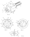
- Fig.1,2 are typical, octagonal profile bars 1 in Section shown as for the compilation of Robotic arms arranged support frames are used.
- the profile bars 1 with each other by so-called Clamping pieces KS are connected, which have no special explanation need, because they are known and not immediate here Interest.
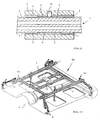
- the in Fig. 10 rod connectors shown in the introduction the aforementioned clamp-turntable combinations, with which the gripper G shown is not immediate to the axes A of the profile rods 1 continuously rotatable can be.
- profile bars shown in section in Fig. 1,2 1 are cross-sectionally octagonal profiles that essentially only by their cross-sectional size and distinguish the number of their grooves 2.
- Overall stability or rigidity of such from the profile bars Assembled carrying frames have the profile bars relatively thick walls, i.e. how they relate to each Diameters are shown, for example.
- an at least externally cylindrical sleeve 3 is essential, which is provided on its inner circumferential surface 4 with two diametrically opposed notches 5, at least two Corresponding notch grooves 6 are provided diametrically opposite on the outer circumferential surface of the respective profile rod 1, which are aligned with the notch grooves 5 of the sleeve 3.
- cylindrical pins 7, which lie against the surfaces 5 ', 6' of the notches 5, 6, are arranged according to the invention. Concerning. the assignment of the pins 7 to the notch grooves 5, 6 is referred to the greatly enlarged illustration in FIG. 8.
- the pins 7 are used in conjunction with the notches 5,6 triangular in the cross-section both for exact centering of the sleeve 3 to the axis A of the profile rod 1 and at the same time for securing the sleeve 3 against rotation with respect to the profile rod 1.
- the sleeve 3 forming the pivot bearing according to the invention has two radially inward facing, radially opposing and in webs 2 of the profile bar 1 matching webs 8 is provided, the grooves 2 and the webs 8 being arranged offset to the notch pairs 5,6.
- the anti-rotation device is thus taken over in particular by the webs 8 engaging in the grooves 2, ie the notch grooves and the dowel pins 7 can in this case be dimensioned smaller, as in the embodiment according to FIG. 3.
- the exemplary embodiment according to FIG. 4 also serves for illustration an embodiment in which the sleeve 3 with its inner surface 4 'essentially the polygonal cross-sectional shape the profile rod 1 is adapted.
- FIG. 5 shows the arrangement of the pivot bearing according to the invention or the sleeve 3 on a profile rod 1 illustrates in perspective, wherein also a clamped on the sleeve 3 fixed Adapter AR is shown with a tool can be attached.
- Adapter AR can fixed in any radial position on the sleeve 3 become.
- the length L of the sleeve 3 corresponds advantageously at least twice the size of their diameter by one such adapter AR also different in the axial direction to be able to position.
- the sleeve 6 is a special embodiment of the sleeve in this respect 3, as this consists of two identical shell halves 3 'is formed, which, as shown, at their joints can be entangled or busy and also there in the area conjugated diameter D 'to each other by means of dashed lines only shown screws 10 are screwed.
- the Heads of the screws 10 must of course in the Screw holes 11 must be accommodated, i.e., they may do not protrude the outer peripheral surface 12 of the sleeve 3.
- FIG. 7 shows an embodiment of the invention clarifies which is a cylindrical tube acts as a profile rod 1, the sleeve 3 despite its inner Excess 13 is exactly centered, which also this embodiment by driving in or pushing in of the two cylindrical pins 7 into those also present here Core groove pairs 5.6 is effected.
- Oversize 13 which is of the order of 1 to 2 mm can, of course, is also the case with the other exemplary embodiments between profile rod 1 and sleeve 3.
- Figure 9 is a section along line IX-IX in Figure 5 by the Pivot bearing shown. It follows that the notches 5.6 both on the sleeve 3 and on the profile rod 1 over the entire length of which is extended. Not with the pins 7 a length corresponding to the length L of the sleeve 3 in the core groove pairs have to drive in with a light press fit the pins 7 in relation to the length of the notches 5 in the Dimension sleeve 3 shorter and from both sides into the notch pairs inserted. In addition, as also from Fig. 9 can be seen for an additional axial fixing of the sleeve 3 provided on the profile rod 1 by a countersunk screw 15 become.
- FIG. 10 The exemplary embodiment shown in FIG. 10 is concerned itself, as mentioned in the introduction, to a support frame TG Clamping pieces KS assembled profile bars 1.
- This Support frame TG is from a robot arm, not shown here worn, on which it is arranged by means of a centrally Connection plate 14 is attached. Since it's just a Example of a support frame TG known type are on this example, no pivot bearing shown according to the invention.
Abstract
Die Erfindung betrifft ein Drehlager an aus Profilstangen (1) gebildeten und insbesondere an Roboterarmen befestigten und von diesen bewegbaren Traggestellen (TG) für die Anbringung von Werkzeugen, wie Spann-, Saug-, Greifvorrichtungen und/oder sonstigen Arbeitshilfsmitteln. Nach der Erfindung ist ein solches Drehlager gebildet aus einer mindesten außen zylindrische Hülse (3), die an ihrer Innenumfangsfläche (4) mit zwei diametral gegenüber angeordneten Kerbnuten (5) versehen ist, und durch mindestens zwei diametral gegenüber an der Außenumfangsfläche der Profilstange (1) angeordnete Kerbnuten (6), die fluchtend zu den Kerbnuten (5) der Hülse (3) ausgerichtet sind, wobei in den Kerbnutenpaaren (5,6) zylindrische, an den Flächen (5',6') der Kerbnuten (5,6) anliegende Stifte (7) angeordnet sind. <IMAGE>The invention relates to a pivot bearing on support frames (TG) formed from profile bars (1) and in particular fastened to robot arms and movable by them for the attachment of tools, such as clamping, suction, gripping devices and / or other working aids. According to the invention, such a rotary bearing is formed from an at least externally cylindrical sleeve (3), which is provided on its inner circumferential surface (4) with two diametrically opposite notches (5), and by at least two diametrically opposite on the outer circumferential surface of the profile rod (1 ) arranged notches (6), which are aligned with the notches (5) of the sleeve (3), wherein in the notch pairs (5,6) cylindrical, on the surfaces (5 ', 6') of the notches (5,6 ) adjacent pins (7) are arranged. <IMAGE>
Description
Die vorliegende Erfindung bezieht sich auf ein Drehlager an aus Profilstangen gebildeten, insbesondere an Roboterarmen befestigten und von diesen bewegbaren Traggestellen für die Anbringung von Werkzeugen, wie Spann-,Saug-,Greifvorrichtungen und/oder sonstigen Arbeitshilfsmitteln.The present invention relates to a rotary bearing formed from profile bars, particularly attached to robot arms and from these movable supports for attachment of tools, such as clamping, suction, gripping devices and / or other work tools.
Derartige Profilstangen werden für die Zusammenstellung von
Traggestellen verwendet, die ihrerseits insbesondere zur Anbringung
an Roboterarmen und für die Anbindung von Werkzeugen,
wie Spann-, Saug-, Greifvorrichtungen und/oder sonstigen Arbeitshilfsmitteln
bestimmt sind.
Bei den dafür vorgesehenen Profilstangen, die untereinander
durch entsprechend profilangepaßte Klemmstücke verbunden werden,
handelt es sich in der Regel um Achteckprofile, die wiederum
in der Regel mit mindestens zwei sich radial gegenüberstehenden
Nuten versehen sind. Achteckprofilstangen werden
deshalb für den genannten Zweck bevorzugt verwendet, um die
profilangepaßten Klemmstücke in acht unterschiedlichen radialen
Orientierungen an den Profilstangen ansetzen zu können,
und zwar jenachdem mit welcher Orientierung die bspw. oben genannten
Werkzeuge am Traggestell sitzen oder welche Orientierung
kreuzende, vom gleichen Klemmstück gehaltene Profilstangen
haben sollen. Eine unmittelbare stufenlose Orientierungseinstellung
solcher Werkzeuge in Bezug auf solche vieleckigen
Profilstangen via Klemmstück ist also nicht möglich
und bedurfte bislang einer besonderen Ausbildung der Klemmstücke
bspw. dahingehend, daß diese in aufwendiger Weise mit
einem Drehscheibenpaar kombiniert werden mußten, wenn eine
stufenlose Verdrehung gewünscht wurde.
Bezgl. an Profilstangen anlegbarer Klemmstücke wird auf das
US-A-4,032,245 verwiesen.
Nach der GB-A-2 275 737 A sind aber auch Traggestelle dieser
Art bekannt, bei denen die Tragstangen aus zylindrischen Profilrohren
bestehen. Da es sich bei den Profilstangen, egal ob
zylindrisch oder vieleckig, um gezogenes Material handelt,
treten hierbei unvermeidbar Ungenauigkeiten auf, die sich
nachteilig für die exakte Einstellung angebundener Werkzeuge
der oben genannten Art bemerkbar machen können.
Außerdem ist ein verdrehfester Sitz in allen radialen Orientierungen
allein durch Verklemmen nicht gewährleistet.Such profile bars are used for the assembly of support frames, which in turn are intended in particular for attachment to robot arms and for the connection of tools, such as clamping, suction, gripping devices and / or other working aids.
The profile bars provided for this purpose, which are connected to one another by appropriately profile-adapted clamping pieces, are generally octagon profiles, which in turn are generally provided with at least two radially opposing grooves. Octagonal profile bars are therefore preferably used for the stated purpose in order to be able to attach the profile-matched clamping pieces in eight different radial orientations to the profile bars, depending on the orientation with which the above-mentioned tools are seated on the support frame or the crossing direction held by the same clamping piece Should have profile bars. An immediate stepless orientation adjustment of such tools in relation to such polygonal profile bars via a clamping piece is therefore not possible and has hitherto required a special design of the clamping pieces, for example in that they had to be combined in a complex manner with a pair of turntables if a continuous rotation was desired.
Reg. Clamping pieces which can be attached to profile rods are referred to US Pat. No. 4,032,245.
According to GB-A-2 275 737 A, support frames of this type are also known, in which the support rods consist of cylindrical profiled tubes. Since the profile bars, whether cylindrical or polygonal, are drawn material, inevitable inaccuracies occur which can have an adverse effect on the exact setting of connected tools of the type mentioned above.
In addition, a twist-proof fit in all radial orientations is not guaranteed by jamming alone.
Die Aufgabe der vorliegenden Erfindung besteht also darin, ein Drehlager an solchen Profilstangen zu schaffen, das auf einfache Weise und mit einfachen Mitteln in Bezug auf die Längsachse der Profilstangen exakt zentrierbar ist.The object of the present invention is therefore a To create swivel bearings on such profile bars, the simple Wisely and with simple means in relation to the longitudinal axis the profile bars can be centered exactly.
Diese Aufgabe ist durch ein Drehlager gemäß unabhängigen Patentanspruch
1 gelöst. Vorteilhafte Weiterbildungen ergeben
sich nach den abhängigen Patentansprüchen 2 bis 8.This object is a pivot bearing according to the
Unter "Drehlager" ist im vorliegenden Zusammenhang selbstverständlich nicht ein Element zu verstehen, um das ständig ein anderes Element drehen soll, sondern gewissermaßen eine inneres, stationäres Lager für ein darauf anzuordnendes Element, das auf diesem "Drehlager" in beliebiger Radialstellung fixiert werden kann.In the present context, "pivot bearing" is a matter of course not an element to understand the constantly is supposed to rotate another element, but in a way one inner, stationary bearing for an element to be placed on it, this on this "pivot bearing" in any radial position can be fixed.
Mit der mindestens außen zylindrischen Hülse wird also an der gewünschten Anordnungsstelle ein verdrehfestes Drehlager der jeweiligen Profilstange zugeordnet, auf dem dann unmittelbar ein entsprechend innenzylindrischer Adapter aufgeschoben wird, der stufenlos in jeder gewünschten radialen Orientierung an der Hülse bzw. dem Drehlager nach der vorliegenden Erfindung fixiert werden kann, was noch näher erläutert wird.With the at least outside cylindrical sleeve is on the desired location a non-rotatable pivot bearing assigned to each profile bar, on which then immediately a corresponding inner cylindrical adapter is pushed on, which is infinitely variable in any desired radial orientation the sleeve or the pivot bearing according to the present invention can be fixed, which is explained in more detail.
An einem solchen Adapter ist dann das an dieser Stelle gewünschte
Werkzeug in geeigneter Weise befestigt.
Da bei derartigen, von Roboterarmen getragenen und in allen
möglichen Richtungen bewegbaren Traggestellen höchstmögliche
Positionierungsgenauigkeiten für die daran angeordneten Werkzeuge
gefordert sind, muß auch die Hülse genau zur Längsachse
der Profilstange zentriert sein, welcher Zentrierungsforderung
die erfindungsgemäßen Kerbnuten mit den zylindrischen Stiften
auf sehr einfache Weise genügen. Diese Stifte stellen dabei
nicht nur eine Verdrehsicherung für die Hülse dar, sondern mit
diesen beiden Stiften ist auch insbesondere für eine exakte
Zentrierung der Hülse zur Achse der Profilstange gesorgt.The tool desired at this point is then fastened in a suitable manner to such an adapter.
Since the highest possible positioning accuracies are required for the tools arranged on them, supported by robot arms and movable in all possible directions, the sleeve must also be centered exactly on the longitudinal axis of the profile rod, which centering requirement the notches according to the invention with the cylindrical pins meet in a very simple manner . These pins not only represent an anti-rotation device for the sleeve, but with these two pins, in particular, an exact centering of the sleeve to the axis of the profile rod is ensured.
Da ferner derartige Profilstangen für den genannten Zweck der Erstellung von robotergetragenen und bewegten Trageinrichtungen, wie vorerwähnt, in der Regel und insbesondere bei vieleckigen Querschnitten auch mit mindestens zwei Nuten versehen sind, besteht nach der vorliegenden Erfindung eine vorteilhafte Ausgestaltung am Drehlager darin, daß die Hülse mit zwei radial nach innen weisenden, sich radial gegenüberstehenden und in Nuten der Profilstange passenden und eingreifenden Stegen versehen ist, wobei die Nuten und die Stege versetzt zu den Kerbnutenpaaren angeordnet sind. Bei dieser Ausführungsform nehmen also insbesondere und vorteilhaft die Stege der Hülse an der Verdrehsicherung teil.Since such profile bars for the stated purpose of Creation of robot-carried and moving support devices, as mentioned, usually and in particular at polygonal cross sections also provided with at least two grooves are, according to the present invention, an advantageous Design on the pivot bearing in that the sleeve with two radially inward facing, radially opposite and fitting and engaging in grooves of the profile bar Is provided webs, the grooves and the webs offset the notch pairs are arranged. In this embodiment So take the webs in particular and advantageously Part of the anti-rotation lock.
Das erfindungsgemäße Drehlager und dessen vorteilhaften Weiterbildungen und Ausführungsformen werden nachfolgend anhand der zeichnerischen Darstellung von Ausführungsbeispielen näher erläutert.The pivot bearing according to the invention and its advantageous developments and embodiments are described below the drawing of exemplary embodiments closer explained.
Es zeigt
- Fig.1
- einen Schnitt durch eine achteckige Profilstange mit vier Nuten;
- Fig.2
- einen Schnitt durch eine achteckige Profilstange mit zwei Nuten;
- Fig.3
- einen Schnitt durch eine Profilstange mit dem auf ihr zentriert angeordneten Drehlager;
- Fig.4
- einen entsprechenden Schnitt gemäß Fig.3 in anderer Ausführungsform;
- Fig.5
- in perspektivischer Darstellung eine Profilstange mit dem erfindungsgemäßen Drehlager und einem darauf befestigtem Adapter;
- Fig.6
- im Schnitt eine weitere Ausführungsform des Drehlalagers in Verbindung mit einer Profilstange gemäß Fig.2;
- Fig.7
- im Schnitt das Drehlager in Verbindung mit einem im Querschnitt kreisförmigen Rohr als Profilstange;
- Fig.8
- stark vergrößert einen Schnitt durch den Anordnungsbereich eines Kerbnutenpaares;
- Fig.9
- einen Schnitt durch das Drehlager längs Linie IX-IX in Fig.5 und
- Fig. 10
- in perspektivischer Darstellung ein Ausführungsbeispiel eines Traggestelles für die Erfassung und den Transport eines Karosseriebleches.
- Fig. 1
- a section through an octagonal profile bar with four grooves;
- Fig. 2
- a section through an octagonal profile bar with two grooves;
- Fig. 3
- a section through a profile rod with the pivot bearing arranged centered on it;
- Fig. 4
- a corresponding section according to Figure 3 in another embodiment;
- Fig. 5
- a perspective view of a profile rod with the pivot bearing according to the invention and an adapter fastened thereon;
- Fig. 6
- in section a further embodiment of the rotary bearing in connection with a profile rod according to Figure 2;
- Fig. 7
- on average the pivot bearing in connection with a tube with a circular cross section as a profile rod;
- Fig. 8
- greatly enlarged a section through the arrangement area of a pair of notches;
- Fig. 9
- a section through the pivot bearing along line IX-IX in Fig.5 and
- Fig. 10
- a perspective view of an embodiment of a support frame for the detection and transport of a body panel.
In den Fig.1,2 sind typische, achteckige Profilstangen 1 im
Schnitt dargestellt, wie sie für die Zusammenstellung von an
Roboterarmen angeordneten Traggestellen Verwendung finden. Ein
solches Traggestell ist nur als Beispiel in Fig.10 verdeutlicht,
wobei die Profilstangen 1 untereinander durch sogenannte
Klemmstücke KS verbunden sind, die keiner besonderen Erläuterung
bedürfen, da bekannt und hier nicht von unmittelbarem
Interesse. Hingewiesen sei nur darauf, daß es sich bei den in
Fig.10 dargestellten Stangenverbindern um die in der Einleitung
vorerwähnten Klemmstück-Drehscheiben-Kombinationen handelt,
mit denen die dargestellten Greifer G nicht unmittelbar
zu den Achsen A der Profilstangen 1 stufenlos drehbar eingestellt
werden können.In Fig.1,2 are typical,
Bei den in den Fig.1,2 im Schnitt dargestellten Profilstangen
1 handelt es sich um im Querschnitt achteckige Profile, die
sich im wesentlich lediglich durch ihre Querschnittsgröße und
die Anzahl ihrer Nuten 2 unterscheiden. Mit Rücksicht auf die
Gesamtstabilität bzw. Steifigkeit solcher aus den Profilstangen
zusammengestellter Tragegestelle haben die Profilstangen
relativ dicke Wandstärken, d.h., wie sie in Bezug auf den jeweiligen
Durchmesser bspw. dargestellt sind. In the profile bars shown in section in Fig. 1,2
1 are cross-sectionally octagonal profiles that
essentially only by their cross-sectional size and
distinguish the number of their
Für das Drehlager nach der vorliegenden Erfindung, das an solchen
Profilstangen 1 ausgebildet werden soll, ist unter Verweis
auf Fig.3 wesentlich eine mindesten außen zylindrische
Hülse 3, die an ihrer Innenumfangsfläche 4 mit zwei diametral
gegenüber angeordneten Kerbnuten 5 versehen ist, wobei mindestens
zwei diametral gegenüber an der Außenumfangsfläche der
jeweiligen Profilstange 1 angeordnete, entsprechende Kerbnuten
6 vorgesehen sind, die fluchtend zu den Kerbnuten 5 der Hülse
3 ausgerichtet sind. In den so gebildeten Kerbutenpaaren 5,6
sind dabei erfindungsgemäß zylindrische, an den Flächen 5',6'
der Kerbnuten 5,6 anliegende Stifte 7 angeordnet.
Bzgl. der Zuordnung der Stifte 7 zu den Kerbnuten 5,6 wird auf
die stark vergrößerte Darstellung in Fig.8 verwiesen. Die
Stifte 7 dienen in Verindung mit den im Querschitt dreieckigen
Kerbnuten 5,6 sowohl zur exakten Zentrierung der Hülse 3 zur
Achse A der Profilstange 1 als auch gleichzeitig zur Verdrehsicherung
der Hülse 3 gegenüber der Profilstange 1.For the rotary bearing according to the present invention, which is to be formed on
Concerning. the assignment of the
Da, wie vorerwähnt, für die vorliegenden Zweck, insbesondere
Profilstangen gemäß der Fig.1,2 verwendet werden, die also mit
Nuten 3 versehen sind, besteht eine vorteilhafte Weiterbildung
gemäß Fig.4 darin, daß die das erfindungsgemäße Drehlager bildende
Hülse 3 mit zwei radial nach innen weisenden, sich radial
gegenüberstehenden und in Nuten 2 der Profilstange 1 passenden
Stegen 8 versehen ist, wobei die Nuten 2 und die Stege
8 versetzt zu den Kerbnutenpaaren 5,6 angeordnet sind.
Die Verdrehsicherung wird hierbei also insbesondere von den in
die Nuten 2 eingreifenden Stegen 8 übernommen, d.h., die Kerbnuten
und die Päßstifte 7 können in diesem Falle kleiner dimensioniert
werden, wie beim Ausführungsbeispiel nach Fig.3.Since, as mentioned above, for the present purpose, in particular profile bars according to FIG. 1, 2 are used, which are thus provided with
The anti-rotation device is thus taken over in particular by the
Das Ausführungsbeispiel gemäß Fig.4 dient auch zur Darstellung
einer Ausführungsform, bei der die erfindungsgemäße Hülse 3
mit ihrer Innenfläche 4' im wesentlichen der vieleckigen Querschnittsform
der Profilstange 1 angepaßt ist. The exemplary embodiment according to FIG. 4 also serves for illustration
an embodiment in which the
In Fig.5 ist die Anordnung des erfindungsgemäßen Drehlagers
bzw. der Hülse 3 auf einer Profilstange 1 perspektivisch verdeutlicht,
wobei auch ein auf der Hülse 3 aufgeklemmt fixierter
Adapter AR mit dargestellt ist, an dem dann ein Werkzeug
befestigt werden kann. Ein solcher Adapter AR kann also
in jeder beliebigen radialen Stellung an der Hülse 3 fixiert
werden. Die Länge L der Hülse 3 entspricht dabei vorteilhaft
mindestens der doppelten Größe ihres Durchmessers, um einen
solchen Adapter AR auch in axialer Richtung unterschiedlich
positionieren zu können.5 shows the arrangement of the pivot bearing according to the invention
or the
In Fig.6 ist eine insoweit besondere Ausführungsform der Hülse
3 dargestellt, als diese aus zwei identischen Schalenhälften
3' gebildet ist, die, wie dargestellt, an ihren Stoßstellen
verschränkt oder geschäftet sein können und auch dort im Bereich
konjugierter Durchmesser D' miteinander mittels nur gestrichelt
dargestellter Schrauben 10 verschraubt sind. Die
Köpfe der Schrauben 10 müssen dabei selbstverständlich in den
Schraubenbohrungen 11 mit untergebracht sein, d.h., diese dürfen
die Außenumfangsfläche 12 der Hülse 3 nicht überragen.6 is a special embodiment of the sleeve in this
In Fig.7 ist schließlich noch eine Ausführungsform der Erfindung
verdeutlicht, bei der es sich um eine zylindrisches Rohr
als Profilstange 1 handelt, der die Hülse 3 trotz ihres inneren
Übermaßes 13 genau zentrisch zuzuordnen ist, was auch bei
dieser Ausführungsform durch das Eintreiben bzw. Einschieben
der beiden zylindrischen Stifte 7 in die auch hierbei vorhandenen
Kernutenpaare 5,6 bewirkt wird. Das hier angesprochene
Übermaß 13, das durchaus in der Größenordnung 1 bis 2 mm betragen
kann, ist natürlich auch bei den anderen Ausführungsbeispielen
zwischen Profilstange 1 und Hülse 3 vorhanden.Finally, FIG. 7 shows an embodiment of the invention
clarifies which is a cylindrical tube
acts as a
In Fig.9 ist ein Schnitt längs Linie IX-IX in Fig.5 durch das
Drehlager dargestellt. Hieraus ergibt sich, daß die Kerbnuten
5,6 sowohl an der Hülse 3 als auch an der Profilstange 1 über
deren ganze Länge erstreckt sind. Um die Stifte 7 nicht mit
einer der Länge L der Hülse 3 entsprechenden Länge in die Kernutenpaare
mit leichtem Preßsitz einschlagen zu müssen, sind
die Stifte 7 in Bezug auf die Länge der Kerbnuten 5 in der
Hülse 3 kürzer bemessen und von beiden Seiten in die Kerbnutenpaare
eingeschoben. Außerdem kann, wie ebenfalls aus Fig.9
ersichtlich, für eine zusätzliche axiale Festlegung der Hülse
3 an der Profilstange 1 durch eine Senkschraube 15 gesorgt
werden.In Figure 9 is a section along line IX-IX in Figure 5 by the
Pivot bearing shown. It follows that the notches
5.6 both on the
Beim in Fig.10 dargestellten Ausführungsbeispiel handelt es
sich, wie einleitend erwähnt, um zu einem Traggestell TG mittels
Klemmstücken KS zusammengefügte Profilstangen 1. Dieses
Traggestell TG wird von einem hier nicht dargestellten Roboterarm
getragen, an dem es mittels einer zentrisch angeordneten
Verbindungsplatte 14 befestigt ist. Da es sich nur um ein
Beispiel für ein Traggestell TG bekannter Art handelt, sind an
diesem Beispiel keine Drehlager nach der Erfindung dargestellt.The exemplary embodiment shown in FIG. 10 is concerned
itself, as mentioned in the introduction, to a support frame TG
Clamping pieces KS assembled profile bars 1. This
Support frame TG is from a robot arm, not shown here
worn, on which it is arranged by means of a centrally
Claims (8)
gekennzeichnet durch
eine mindesten außen zylindrische Hülse (3), die an ihrer Innenumfangsfläche (4) mit zwei diametral gegenüber angeordneten Kerbnuten (5) versehen ist, und durch mindestens zwei diametral gegenüber an der Außenumfangsfläche der Profilstange (1) angeordnete Kerbnuten (6), die fluchtend zu den Kerbnuten (5) der Hülse (3) ausgerichtet sind, wobei in den Kerbnutenpaaren (5,6) zylindrische, an den Flächen (5',6') der Kerbnuten (5,6) anliegende Stifte (7) angeordnet sind.Pivot bearings on support frames (TG) formed from profile bars (1) and in particular fastened to robot arms and movable by them for the attachment of tools, such as clamping, suction, gripping devices and / or other working aids,
marked by
an at least externally cylindrical sleeve (3), which is provided on its inner circumferential surface (4) with two diametrically opposite notch grooves (5), and by at least two diametrically opposite notch grooves (6) arranged on the outer circumferential surface of the profile bar (1), which are aligned are aligned with the notch grooves (5) of the sleeve (3), cylindrical pins (7) lying against the surfaces (5 ', 6') of the notch grooves (5,6) being arranged in the notch pairs (5,6).
dadurch gekennzeichnet,
daß die Kerbnuten (5,6) über die ganze Länge sowohl der Hülse (3) als auch der Profilstange (1) erstreckt sind.Pivot bearing according to claim 1,
characterized,
that the notches (5,6) extend over the entire length of both the sleeve (3) and the profile rod (1).
dadurch gekennzeichnet,
daß die in Bezug auf die Länge der Kerbnuten (5,6) kürzer bemessenen Stifte (7) von beiden Seiten in die Kerbnuten (5,6) eingeschoben sind.Pivot bearing according to claim 1 or 2
characterized,
that the pins (7), which are shorter in relation to the length of the notches (5, 6), are inserted into the notches (5, 6) from both sides.
dadurch gekennzeichnet,
daß die Hülse (3) mit mindestens einer Senkschraube (15) gegen axialen Verschub an der Profilstange (1) festgelegt ist. Pivot bearing according to one of claims 1 to 3,
characterized,
that the sleeve (3) is fixed with at least one countersunk screw (15) against axial displacement on the profile rod (1).
dadurch gekennzeichnet,
däß die Innenfläche (4') der Hülse (3), im Querschnitt gesehen, im wesentlichen dem Querschnitt der Profilstange (1) entspricht.Pivot bearing according to one of claims 1 to 4,
characterized,
däß the inner surface (4 ') of the sleeve (3), seen in cross section, corresponds essentially to the cross section of the profile rod (1).
dadurch gekennzeichnet,
daß die Hülse (3) aus zwei Halbschalen (3') gebildet ist und daß die Halbschalen (3') im Bereich ihrer Wand auf zur Achse (A) der Profilstange gleichabständigen, konjugierten Durchmessern (D') miteinander verschraubt sind.Pivot bearing according to one of claims 1 to 5,
characterized,
that the sleeve (3) is formed from two half-shells (3 ') and that the half-shells (3') are screwed together in the region of their wall on conjugated diameters (D ') which are equally spaced from the axis (A) of the profile rod.
dadurch gekennzeichnet,
daß die Hülse (3) mit zwei radial nach innen weisenden, sich radial gegenüberstehenden und in Nuten (2) der Profilstange (1) passenden Stegen (8) versehen ist, die Nuten (2) und die Stege (8) sind versetzt zu den Kerbnutenpaaren (5,6) angeordnet.Pivot bearing according to one of claims 1 to 6,
characterized,
that the sleeve (3) is provided with two radially inwardly facing, radially opposite and in grooves (2) of the profile rod (1) matching webs (8), the grooves (2) and the webs (8) are offset from the Notched groove pairs (5,6) arranged.
dadurch gekennzeichnet,
daß die Hülse (3) mit einer Länge (L) bemessen ist, die mindestens dem doppelten Außendurchmesser (D) der Hülse (3) entspricht.Pivot bearing according to one of claims 1 to 7,
characterized,
that the sleeve (3) is dimensioned with a length (L) which corresponds to at least twice the outer diameter (D) of the sleeve (3).
Applications Claiming Priority (2)
| Application Number | Priority Date | Filing Date | Title |
|---|---|---|---|
| US09/501,878 US6318926B1 (en) | 2000-02-10 | 2000-02-10 | Pivot bearing provided on support structures formed of shaped bars |
| US501878 | 2000-02-10 |
Publications (2)
| Publication Number | Publication Date |
|---|---|
| EP1123783A2 true EP1123783A2 (en) | 2001-08-16 |
| EP1123783A3 EP1123783A3 (en) | 2002-03-20 |
Family
ID=23995386
Family Applications (1)
| Application Number | Title | Priority Date | Filing Date |
|---|---|---|---|
| EP00106300A Withdrawn EP1123783A3 (en) | 2000-02-10 | 2000-03-23 | Pivoting assembly for positioning tools on support structures |
Country Status (2)
| Country | Link |
|---|---|
| US (1) | US6318926B1 (en) |
| EP (1) | EP1123783A3 (en) |
Cited By (1)
| Publication number | Priority date | Publication date | Assignee | Title |
|---|---|---|---|---|
| WO2007120795A2 (en) * | 2006-04-13 | 2007-10-25 | Norgren Automotive, Inc. | Apparatus for accurately positioning and supporting modular tooling |
Families Citing this family (2)
| Publication number | Priority date | Publication date | Assignee | Title |
|---|---|---|---|---|
| FR2855089B1 (en) * | 2003-05-21 | 2006-09-22 | A M G | PREHENSING BODY FOR RETAINING A WORKPIECE BY A MANIPULATOR, AGENCY IN TINTED STRUCTURE COMPRISING A BEAM ON WHICH ARTICLES OF ARMS CARRIED OF A RETENTION HEAD ARE JOINED |
| WO2004103652A2 (en) * | 2003-05-21 | 2004-12-02 | Societe Amg | Gripper element for retaining a part to be displaced by a manipulator, provided with a layered structure comprising a beam on which carrier arms for a retainer head are disposed |
Citations (2)
| Publication number | Priority date | Publication date | Assignee | Title |
|---|---|---|---|---|
| US4032245A (en) | 1976-07-09 | 1977-06-28 | Gramor Machine Company | Agricultural equipment clamp |
| GB2275737A (en) | 1993-03-05 | 1994-09-07 | Donald Lee Hufford | Instrument support boom assemblies and unions thereof |
Family Cites Families (6)
| Publication number | Priority date | Publication date | Assignee | Title |
|---|---|---|---|---|
| US3147829A (en) * | 1960-06-15 | 1964-09-08 | Sealing Corp Of America | Telescoping elevating support |
| CA893414A (en) * | 1970-08-25 | 1972-02-22 | W. Reilly Frederick | Connector for joining tubular members |
| DE4317579A1 (en) * | 1993-05-27 | 1994-12-01 | Kurt Ehrenberg | Clamping connection between a sleeve and a shaft |
| DE29501158U1 (en) * | 1995-01-25 | 1995-03-30 | Electrolux Corporate Patents & | Locking device for a drive shaft |
| GB2304792A (en) * | 1995-09-08 | 1997-03-26 | Nastech Europ Ltd | Snap connection system |
| DE29905687U1 (en) * | 1999-03-27 | 1999-07-08 | Sta Co Mettallerzeugnisse Gmbh | Carrying device |
-
2000
- 2000-02-10 US US09/501,878 patent/US6318926B1/en not_active Expired - Fee Related
- 2000-03-23 EP EP00106300A patent/EP1123783A3/en not_active Withdrawn
Patent Citations (2)
| Publication number | Priority date | Publication date | Assignee | Title |
|---|---|---|---|---|
| US4032245A (en) | 1976-07-09 | 1977-06-28 | Gramor Machine Company | Agricultural equipment clamp |
| GB2275737A (en) | 1993-03-05 | 1994-09-07 | Donald Lee Hufford | Instrument support boom assemblies and unions thereof |
Cited By (3)
| Publication number | Priority date | Publication date | Assignee | Title |
|---|---|---|---|---|
| US8108978B2 (en) | 2005-07-06 | 2012-02-07 | Norgren Automation Solutions, Inc. | Apparatus for accurately positioning and supporting modular tooling |
| WO2007120795A2 (en) * | 2006-04-13 | 2007-10-25 | Norgren Automotive, Inc. | Apparatus for accurately positioning and supporting modular tooling |
| WO2007120795A3 (en) * | 2006-04-13 | 2008-04-17 | Norgren Automotive Inc | Apparatus for accurately positioning and supporting modular tooling |
Also Published As
| Publication number | Publication date |
|---|---|
| US6318926B1 (en) | 2001-11-20 |
| EP1123783A3 (en) | 2002-03-20 |
Similar Documents
| Publication | Publication Date | Title |
|---|---|---|
| EP1330611B1 (en) | Telescopic arm | |
| EP1819480B1 (en) | Workpiece positioning device | |
| DE19521710B4 (en) | Panoramic head for optical devices, in particular for cameras | |
| EP0626604A2 (en) | Flexible endoscope tube | |
| EP0614035A1 (en) | Ceiling mount | |
| WO2015144613A1 (en) | Robot arm and assembly set | |
| DE3434224A1 (en) | REMOVABLE FRAME | |
| EP2700608A1 (en) | Mounting plate and lifting column | |
| DE102020125969A1 (en) | LINEAR EXPANSION MECHANISM | |
| DE3636194C1 (en) | Homokinetic double joint | |
| WO2000045991A1 (en) | Parallel kinematics machine | |
| WO1999008832A1 (en) | Device for moving and positioning an object in a plane | |
| DE102012108031A1 (en) | Holder for a joining device | |
| EP2926759A2 (en) | Holding arm for positioning a medical instrument or a medical appliance | |
| DE102006030314A1 (en) | Bearing cage with a variety of connecting straps | |
| DE3636462C2 (en) | ||
| EP1123783A2 (en) | Pivoting assembly for positioning tools on support structures | |
| EP1249406B1 (en) | Return device for a conveyor system | |
| EP0585563B1 (en) | Device for generating a synchronous translational/rotational movement | |
| EP0034640B1 (en) | Screw mechanism | |
| DE102019130855A1 (en) | Connection system and shelving system | |
| DE3042427C2 (en) | Twin screw extruder for processing thermoplastic molding compounds, in particular plastics | |
| EP2031175A1 (en) | Side section for a roller shutter housing | |
| EP1980359B1 (en) | Adjustment unit | |
| DE10015186B4 (en) | lens Mounting |
Legal Events
| Date | Code | Title | Description |
|---|---|---|---|
| PUAI | Public reference made under article 153(3) epc to a published international application that has entered the european phase |
Free format text: ORIGINAL CODE: 0009012 |
|
| AK | Designated contracting states |
Kind code of ref document: A2 Designated state(s): AT BE CH CY DE DK ES FI FR GB GR IE IT LI LU MC NL PT SE |
|
| AX | Request for extension of the european patent |
Free format text: AL;LT;LV;MK;RO;SI |
|
| PUAL | Search report despatched |
Free format text: ORIGINAL CODE: 0009013 |
|
| AK | Designated contracting states |
Kind code of ref document: A3 Designated state(s): AT BE CH CY DE DK ES FI FR GB GR IE IT LI LU MC NL PT SE |
|
| AX | Request for extension of the european patent |
Free format text: AL;LT;LV;MK;RO;SI |
|
| AKX | Designation fees paid | ||
| REG | Reference to a national code |
Ref country code: DE Ref legal event code: 8566 |
|
| STAA | Information on the status of an ep patent application or granted ep patent |
Free format text: STATUS: THE APPLICATION IS DEEMED TO BE WITHDRAWN |
|
| 18D | Application deemed to be withdrawn |
Effective date: 20020921 |