EP1123680B1 - Shower tray and doors - Google Patents
Shower tray and doors Download PDFInfo
- Publication number
- EP1123680B1 EP1123680B1 EP01301135A EP01301135A EP1123680B1 EP 1123680 B1 EP1123680 B1 EP 1123680B1 EP 01301135 A EP01301135 A EP 01301135A EP 01301135 A EP01301135 A EP 01301135A EP 1123680 B1 EP1123680 B1 EP 1123680B1
- Authority
- EP
- European Patent Office
- Prior art keywords
- shower
- grille
- channels
- door
- tray
- Prior art date
- Legal status (The legal status is an assumption and is not a legal conclusion. Google has not performed a legal analysis and makes no representation as to the accuracy of the status listed.)
- Expired - Lifetime
Links
Images


Classifications
-
- A—HUMAN NECESSITIES
- A47—FURNITURE; DOMESTIC ARTICLES OR APPLIANCES; COFFEE MILLS; SPICE MILLS; SUCTION CLEANERS IN GENERAL
- A47K—SANITARY EQUIPMENT NOT OTHERWISE PROVIDED FOR; TOILET ACCESSORIES
- A47K3/00—Baths; Douches; Appurtenances therefor
- A47K3/28—Showers or bathing douches
- A47K3/30—Screens or collapsible cabinets for showers or baths
- A47K3/36—Articulated screens
- A47K3/362—Articulated screens comprising sliding and articulated panels
-
- A—HUMAN NECESSITIES
- A47—FURNITURE; DOMESTIC ARTICLES OR APPLIANCES; COFFEE MILLS; SPICE MILLS; SUCTION CLEANERS IN GENERAL
- A47K—SANITARY EQUIPMENT NOT OTHERWISE PROVIDED FOR; TOILET ACCESSORIES
- A47K3/00—Baths; Douches; Appurtenances therefor
- A47K3/28—Showers or bathing douches
- A47K3/40—Pans or trays
Definitions
- the present invention relates to a shower tray and doors or screens for use with a shower tray, in particular a shower tray having application for people of reduced mobility.
- DE-A-36000945 which is considered to constitute the closest prior art, describes a shower system comprising a shower tray, a cover grille, and at least one retractable shower door assembly, wherein the shower tray comprises a shower area having a drainage channel along the edge thereof, the shower area having a floor sloping towards the drainage channel, wherein the drainage channel is provided with means to support the cover grille thereover, the cover grille being positioned, shaped and dimensioned to provide an elongate drainage aperture between the edge cover grille and the shower area edge and the shower tray outer edge, wherein the cover grille, includes means adapted to receive a lower edge of the retractable shower door.
- the present invention provides a shower system comprising a shower tray including a cover grille and at least one retractable shower door assembly, wherein the shower tray comprises a general rectilinear shower area having drainage channels along the, in use, front edge thereof and at least one other edge adjacent thereto, the showering area having a floor sloping towards the drainage channels; wherein the drainage channels are provided with means to support the cover grille thereover, the cover grille being positioned, shaped and dimensioned to provide an elongate drainage aperture between the shower area edges and the corresponding outer edges of the shower tray, wherein the grille includes elongate changes adapted to receive and support a lower edge of the retractable shower door; and wherein each drainage channel has a first sidewall adjoining the edge of the shower area and a second sidewall adjoining the edge of the shower tray; wherein the first and second sidewalls are formed with respective grille-support members and wherein a raised longitudinal ridge is provided within the drainage channel intermediate the first and second side walls, thereby defining a primary flow
- the ridge is formed closer to the second sidewall than to the first sidewall.
- the ride is discontinuous to allow fluid communication between the primary and secondary flow channels.
- At least one of the grille-support members associated with the first and second sidewalls comprises a plurality of generally arcuate members projecting outwardly from the respective sidewall.
- the shower door assembly comprises two retractable shower doors each being mountable upon respective walls adjacent the shower area and being adapted to pivot outwardly from or inwardly over the shower area pivoting at a point substantially adjacent the respective wall, wherein each door comprises a plurality of door panels which are adapted in said elongate channels of said grille.
- the door panels are adapted to run in the elongate grille channels by means of runners or wheels being provided in a lower surface of each door panel.
- each door is adapted to pivot outwardly by being provided with a mechanism which includes a lifting mechanism to raise the runners or wheels of each panel out of engagement with the changes of the grille.
- the lifting mechanism includes a cap or pillar secured to the edge of that door panel adjacent the pivot point, which cap is pivotally mounted upon an intermediate element slidably mounted within a wall-mountable retaining channel; and wherein a hook element is mounted on the intermediate element for pivotal movement about a horizontal axis such that a rotational element and wherein such pivotal movement is preferably actuated by means of a hook arm in the hook element engaging a rod or pin mounted eccentrically upon a rotatable pivot disc.
- each door comprises at least a first and a second door panel, wherein each panel is mounted between respective top and bottom rails and the first panel includes a respective channel on a first face thereof each of which channels receives a respective slider element secured to the second face of the second panel; wherein each slider element is constrained to slide within its respective channel by top and bottom end caps including a retractable insert having extended legs adapted to bear against a respective slider element.
- pivot disc is caused to rotate by means of a handle connected thereto.
- the pivot disc may be caused to rotate by electromechanical means such as an electric or hydraulic motor.
- a linear motion to the intermediate element is caused by means of a control cable preferably a Bowden cable, being coupled at one end thereof the intermediate element, and at the other end thereof to actuating means, typically a handle or electromechanical means.
- actuating means typically a handle or electromechanical means.
- FIGS 1 to 3 illustrates the principle elements of a shower tray 10 in accordance with the present invention.
- the tray 10 includes a rectangular shower area 11 and front 12 and side 13 drainage channels along two adjacent edges thereof.
- the shower area 11 is raised at its rearward edge in order to produce an incline towards the drainage channels.
- the shower area 11 is divided into two drainage areas 14,15, each directing the flow of water predominantly into one of the channels 12,13.
- the tray is provided with upstanding splash-backs 16,17 around the sides not provided with drainage channels and a grille 30 over substantially the entire length of the drainage channels 12,13.
- the channels 12,13 need to be let into the surface of the floor by removal, as shown, of sections 20 of floorboards 25.
- the depth of the shower tray in the area of the channels is, accordingly, chosen to correspond to the thickness of a standard floorboard such that the bottom surface 22 (in Figure 2) of the tray is supported upon one or more floor joists 26. Additional support may also be provided to give support to the tray between the joists. For example, the whole area below the shower tray may be excavated and a board put in place to create a continuous and flat surface upon which the tray can sit.
- the shower tray has a drainage hole 23 at one end of a channel, the particular position being chosen such that the associated drain gully 24 occupies a position between adjacent floor joists.
- no drainage hole is provided but an enlarged flat area 21 is provided at the end of side drainage channel 13 for on-site cutting of a drainage hole in an appropriate position to avoid underlying floor joists.
- a corresponding channel 20 is chased out of the floor, together with the necessary space for the drainage components 24.
- shower trays in accordance with the present invention will be provided in a range of configurations.
- the side channel 13 may be on the left or the right hand side and for each of these configurations, the drain may be provided at the end of the side channel 13 or at the end of the front channel 12.
- Alternative embodiments can be envisaged such as one in which the drainage hole is provided at the junction of the two channels 12,13.
- drainage of water from the tray will be by conventional gravity means.
- pump-assisted drainage may be provided.
- the outer edge of the tray 10 is stepped to provide regions for overlapping floor coverings.
- the tray abuts the adjacent floor board 25.
- the tray has a recessed or stepped portion 31 to receive a sheet of waterproofed board 27 such that the waterproofed board overlaps both the floorboard 25 and the tray 10.
- the final floor covering 28 typically a slip resistant linoleum-type material, such as that sold under the trade mark 'Altro', such that final floor covering 28 overlaps the waterproofed board 27 and the tray 10.
- the shower area 11 of the tray may also be recessed to receive a sheet of matching floor covering 33 although this is not an essential feature.
- the channel has a first sidewall 40 adjoining the edge of the shower area 11, curving downwardly towards the base 41 of the channel 12 and a second sidewall 43 which may also be curved.
- First sidewall 40 includes a plurality of arcuate grille-support members 42 projecting outwardly therefrom.
- Second side wall 43 includes a ledge 44 also acting as a grille support.
- arcuate grille-support members 42 are replaced by a continuous support ledge.
- a raised longitudinal ridge 45 is provided within the channel intermediate sidewalls to provide additional grille support, thereby dividing the drainage channel into two flow channels, a primary flow channel 50 adjacent the showering area 14 and a secondary flow channel 51 adjacent the outer edge of the shower tray. As shown, preferably the raised ridge 45 is positioned closer to the outer edge of the shower tray than it is to the showering area, providing a primary flow channel 50 of greater width than the secondary flow channel.
- the grille 60 itself will now be described in further detail with particular reference to Figures 5 and 6 which show a section of grille to be positioned at the junction between the two channels 12,13.
- the grille 60 includes a plurality of longitudinal drainage apertures 61 formed in channels 62 which encourage drainage therethrough. Alternatively, the apertures could be axial or diagonally orientated. As is most clearly seen in Figure 6, the grille is provided with a slight camber to encourage drainage.
- the grille 60 includes downwardly depending inner leg components or ledge 63 which engage corresponding ledges 64 formed in the arcuate grille support members 42.
- the grille and arcuate grille support members are dimensioned so as to provide a spacing for drainage between the inner edge 64 of the grille and the first sidewall of the channel.
- the inner edge 64 of the grille is also provided with an angled profile to provide a clear drainage pathway from the shower area to the drainage flow channel 50.
- the underside of the grille 60 includes an elongate track 65 depending therefrom and being profiled to rest, for support, on ridge 45 of the drainage channel.
- raised ridge 45 is discontinuous and includes a number of overflow channels 52 to allow fluid communication between the two flow channels 50,51.
- raised ridge 45 is continuous and elongate track 65 includes discontinuities to provide the desired fluid communication. To ensure adequate flow in this arrangement, typically ridge 45 will be lower in height than in the embodiment illustrated and elongate track 65 is extended downwardly to contact the ridge 45.
- the grille 30 may be a unitary element. However, preferably, the grille is formed by a number of discrete grille elements.
- the upper surface of the grille includes a plurality of further channels 70, preferably perforated for drainage, which act as running tracks for a sliding door assembly 71 ( Figure 4).
- a sliding door assembly 71 Figure 4
- the present invention ensures that there is little or no flooding of water outside the shower doors. Any water that may, for example, splash over the top of any shower doors will fall onto that part of the grille outside the doors, draining through the grille and into the distal flow channel. This is a significant advantage of the present invention.
- the shower door assembly 71 includes a long door 80 and a short door 81 and, by way of example, the operation of the long door will now be described in a more detail.
- Long door 80 comprises three panels, a hinge panel 82, a central panel 83 and an end panel 84.
- Each panel which may be made of toughened or safety glass or of a polymeric material such as acrylic or polycarbonate, is mounted for slidable movement with respect to each adjacent panel.
- End panel 84 is held between a top rail 90 and bottom rail 91 both of extruded aluminium and including left end caps 92 and right end caps 94.
- Mounted in the lower edge of bottom rail 91 are two wheels 93 which engage the innermost channel 70 of the grille.
- Central panel 83 is similarly mounted between top and bottom rails 90,91, the latter of which includes wheels 93 to run in central channel 70 of the grille.
- Top and bottom rails 90 and 91 of the central panel each include a respective channel 95,96 on the rear face thereof which each receive a respective slider element 100,101 secured to the front face of the end panel.
- Each slider element 100,101 is restrained to slide within its respective channel by top and bottom end caps 98.
- End caps 98 include a removable insert 99 having extended legs 99a. In use in position in the end cap, the legs 99a of each insert 99 bear against the respective slider element arresting the sliding movement of the end panel 84 over the central panel 83 typically resulting in an overlap between the two panels of several inches, providing a resilient door.
- tubular elements 105,106 are mounted upon the external vertical edges of the respective end panels. Tubular elements 105,106 include opposing magnetic strip elements which serve to retain the doors when closed and provide a degree of waterproofing.
- Hinge panel 82 is provided with a pillar 119 along its vertical end edge which is adapted to pivot within an intermediate element 120 coupled to a wall adjustment element 121 itself slidably mountable within a wall-mounted retaining channel 122.
- Intermediate element 120 includes means, as shown, in the form of an additional stub component 123, including means for resiliently receiving a distal end of a Bowden cable 124.
- Bowden cable 124 passes over a bar 125 and engages, at its other, proximal end, actuating handle 130 which is located for rotational movement within the wall-mounted retaining channel 122.
- actuating handle 130 As actuating handle 130 is rotated, the proximal end of Bowden cable 124 is pulled downwardly, thus raising the distal end of Bowden cable 124 and with it the stub component 123 and thereby the whole door. With the wheels raised from engagement with the channels of the grille, the door can be swung outwardly.
- FIG. 9 An alternative lifting mechanism is illustrated in Figures 9 to 12.
- a tubular pillar 127 is provided on the vertical edge of the hinge panel 82.
- This cap engages lower and upper hinge plates 125,126 mounted at respective ends of a channel 131 fixedly mounted upon a box-section intermediate element 132 which is adapted to slide in a channel 133 of wall-mounted retaining channel 122.
- Hinge caps 125,126 allow a full pivoting movement of pillar 120 and thus the doors.
- Lifting of the doors is achieved as follows. Secured to intermediate element 132 are two plates 134 and 135. Plates 134 and 135 are shaped as to combine to form a hook plate 140 ( Figure 12) open around three sides.
- hook arm 141 Sandwiched between plates 134,135 of hook plate 140 for pivotal movement is a hook arm 141 having a hook at its uppermost (as shown) end.
- the hook of hook arm 141 engages a pivot rod 142 mounted between two pivot discs 143, 144 at a position adjacent the periphery thereof.
- Pivot discs 143,144 are mounted upon a spindle 145 which engages actuating handle 130.
- Rotation of handle 130 causes hook arm 141 and thus hook plate 140 to lift via a cam action thereby also raising the doors which are then free to pivot open.
- Alternative cam action mechanisms will be readily apparent to those skilled in the art.
- FIG. 14 Such an alternative is illustrated in side view in Figure 14 and in an exploded view in Figure 15.
- the construction of this embodiment is broadly similar to that of Figures 11 and 12.
- the hook assembly 140,141,142,144 is replaced by a cam element 150 operatively mounted upon spindle 145 which engages actuating handle 130.
- Cam element 150 is generally trapezoidal in plan view. Plates 134,135 secured to intermediate element 132 are modified from the embodiment described above by provision of a cut-out portion 151 adapted to engage cam element 150. Plates 134,135 may, of course, be formed from a single component.
- a gas strut or piston 152 is included below plates 134, 135 to act as a damper to slow the decent of the doors
- the doors can also pivot over the shower tray for the purposes of drainage.
- the doors are held in the closed position by means of magnetic strips.
- a simple male cap 150 having a pin depending therefrom mounted on the end cap of one end panel engages a corresponding aperture in a corresponding female cap 151 mounted on the end cap of the other end panel.
- the male and female components can, of course, be reversed with advantageous results in avoiding pooling of water within the cavity of the male cap.
- the shower tray of the present invention provides a number of significant advantages over the prior art, in particular the tray of US 5,243,716.
- the use of a drainage channel around more than one edge of the tray allows the use of lower flow rates, which in turn allows the use of shallower gradients and thus tray depths.
- it allows the use of increased water flows for the same gradients and depths.
- As the doors overlap the grille generally centrally, water hitting the door from the shower can drain freely into the channel. There is no pooling or flooding as occurs with existing shower door designs.
- It also provides a shower tray with true level access on two sides, that is to say, it provides enhanced, open, access, a significant advantage for wheelchair bound users and their carers.
- the shower doors of the present invention provide additional significant advantages to those with disabilities. Users with restricted mobility will tend to lean upon any available surfaces for support. All surfaces in showers designed for the disabled should therefore to be able to bear a significant force, although often such showers are not so designed.
- the present invention satisfies this requirement in a number of aspects.
- lateral movement of the shower doors is resisted to a slight degree by wheels 93 running in the channels 70 of the grille.
- the running of the doors in the channels also allows vertical forces exerted on the top of the doors to be transmitted vertically down to the grille and thus to the shower tray.
- the tray and grille may be made out of many materials as will be apparent to one skilled in the art.
- the tray may be made by vacuum forming, preferably from glass reinforced plastics materials or by infusion or resin transfer moulding.
- the grille may be extruded or moulded, from aluminium, a plastics or resinous materials, optionally reinforced, such as a carbon fibre resin material.
- moulding is a preferred method for the production of the grille as it allows the addition of arcuate vanes or flow directors 110 to the underside surface of the grille (as shown in Figure 13).
- vanes act to direct the flow of water specifically towards the drainage area 21 reducing turbulence and aiding water flow velocity.
- the vanes will be left-handed or right-handed to correspond to the required direction of flow.
- the vanes 110 project approximately 5mm below the level of the inner ledge 63. As the channel 13 slopes downwardly towards the gully 23, the gap between the bottom of the vanes increases from approximately 5mm to around 16-18mm.
Landscapes
- Health & Medical Sciences (AREA)
- Public Health (AREA)
- Epidemiology (AREA)
- General Health & Medical Sciences (AREA)
- Bathtubs, Showers, And Their Attachments (AREA)
- Spinning Or Twisting Of Yarns (AREA)
- Residential Or Office Buildings (AREA)
- Basic Packing Technique (AREA)
Abstract
Description
- The present invention relates to a shower tray and doors or screens for use with a shower tray, in particular a shower tray having application for people of reduced mobility.
- Conventional square shower trays are unacceptably small for people of reduced mobility such as the elderly or disabled. For the disabled and others of reduced mobility, easy access into a shower area is essential. In the design of purpose-built accommodation, level access shower areas can be easily incorporated. However, the mobility of most people deteriorates over the course of a number of years and they will wish to delay leaving their own homes for as long as possible. It is known to remove existing baths and replace them by low-level access shower trays. However, conventionally, such trays sit on the floor of the bathroom in one corner and also include a drain in the comer. To enable the water to drain to the corner, the floor of the shower tray must be inclined towards the drain. This results in the front edge of the tray being raised above floor level, presenting the user with a step to overcome in order to enter the shower area. An example of such a tray is shown in GB 2 270 836A. Even a small step can present a significant obstacle to one whose mobility is impaired, particularly, of course, if that person is wheelchair bound.
- There is a need therefore for a shower tray for which access thereto is at the same level as the surrounding floor. One solution is to excavate the floor covering in order to let the shower tray described above into the floor, but this is not entirely satisfactory particularly if the floor is of concrete construction. An alternative and more satisfactory solution is described in US Patent No 5,243,716. This describes a shower tray draining towards an integral trough positioned adjacent the front (in use) edge of the tray. Only the trough need be let into the floor and provides genuinely level access to the shower tray. The tray is installed between two fixed walls, allowing access from the front only. Nevertheless, there are a number of perceived disadvantages of this tray including the rate of drainage and thus limits on the water flow or power of the shower taken. There are also questions about access, it being the case that users will often have assistance showering from others who also need to be able to gain easy access to the shower tray. It is with these problems in mind that the present invention has been devised.
- DE-A-36000945, which is considered to constitute the closest prior art, describes a shower system comprising a shower tray, a cover grille, and at least one retractable shower door assembly, wherein the shower tray comprises a shower area having a drainage channel along the edge thereof, the shower area having a floor sloping towards the drainage channel, wherein the drainage channel is provided with means to support the cover grille thereover, the cover grille being positioned, shaped and dimensioned to provide an elongate drainage aperture between the edge cover grille and the shower area edge and the shower tray outer edge, wherein the cover grille, includes means adapted to receive a lower edge of the retractable shower door.
- The present invention provides a shower system comprising a shower tray including a cover grille and at least one retractable shower door assembly, wherein the shower tray comprises a general rectilinear shower area having drainage channels along the, in use, front edge thereof and at least one other edge adjacent thereto, the showering area having a floor sloping towards the drainage channels; wherein the drainage channels are provided with means to support the cover grille thereover, the cover grille being positioned, shaped and dimensioned to provide an elongate drainage aperture between the shower area edges and the corresponding outer edges of the shower tray, wherein the grille includes elongate changes adapted to receive and support a lower edge of the retractable shower door; and wherein each drainage channel has a first sidewall adjoining the edge of the shower area and a second sidewall adjoining the edge of the shower tray; wherein the first and second sidewalls are formed with respective grille-support members and wherein a raised longitudinal ridge is provided within the drainage channel intermediate the first and second side walls, thereby defining a primary flow channel adjacent the shower area and a secondary flow channel adjacent the edge of the shower tray.
- Preferably, the ridge is formed closer to the second sidewall than to the first sidewall.
- Preferably the ride is discontinuous to allow fluid communication between the primary and secondary flow channels.
- Preferably, at least one of the grille-support members associated with the first and second sidewalls comprises a plurality of generally arcuate members projecting outwardly from the respective sidewall.
- Preferably, the shower door assembly comprises two retractable shower doors each being mountable upon respective walls adjacent the shower area and being adapted to pivot outwardly from or inwardly over the shower area pivoting at a point substantially adjacent the respective wall, wherein each door comprises a plurality of door panels which are adapted in said elongate channels of said grille.
- Suitably, the door panels are adapted to run in the elongate grille channels by means of runners or wheels being provided in a lower surface of each door panel.
- Preferably, each door is adapted to pivot outwardly by being provided with a mechanism which includes a lifting mechanism to raise the runners or wheels of each panel out of engagement with the changes of the grille.
- Preferably, the lifting mechanism includes a cap or pillar secured to the edge of that door panel adjacent the pivot point, which cap is pivotally mounted upon an intermediate element slidably mounted within a wall-mountable retaining channel; and wherein a hook element is mounted on the intermediate element for pivotal movement about a horizontal axis such that a rotational element and wherein such pivotal movement is preferably actuated by means of a hook arm in the hook element engaging a rod or pin mounted eccentrically upon a rotatable pivot disc.
- Preferably, each door comprises at least a first and a second door panel, wherein each panel is mounted between respective top and bottom rails and the first panel includes a respective channel on a first face thereof each of which channels receives a respective slider element secured to the second face of the second panel; wherein each slider element is constrained to slide within its respective channel by top and bottom end caps including a retractable insert having extended legs adapted to bear against a respective slider element.
- In an alternative embodiment not covered by the appended claims, pivot disc is caused to rotate by means of a handle connected thereto. Alternatively, the pivot disc may be caused to rotate by electromechanical means such as an electric or hydraulic motor.
- In an other alternative embodiment not covered by the appended claims, a linear motion to the intermediate element is caused by means of a control cable preferably a Bowden cable, being coupled at one end thereof the intermediate element, and at the other end thereof to actuating means, typically a handle or electromechanical means.
- The above and other aspects of the present invention will now be described in further detail, by way of example only, with reference to the accompanying figures, in which:
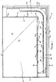
- Figure 1 is a plan view of a first embodiment of a shower tray in accordance with the present invention, with grille panels omitted;
- Figure 2 is a cross-section along the line II-II of Figure 1;
- Figure 3 is an exploded perspective view illustrating a typical installation of a modification of the tray of Figure 1;
- Figure 4 is a part perspective sectional view of a further embodiment of a shower tray in accordance with the present invention, together with shower doors; Figure 5 is a plan view illustrating the principal features of an embodiment of a grille of a shower tray in accordance with the present invention;
- Figure 6 is a cross section along the line VI-VI of Figure 5;
- Figure 7 is an exploded view of a first embodiment of a shower door assembly in accordance with the second aspect of the present invention;
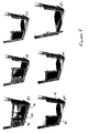
- Figure 8 is a sequence of views illustrating the operation of the shower door assembly of Figure 7;
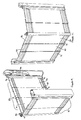
- Figure 9 is a perspective view to one side of a second embodiment of a shower door assembly in accordance with the present invention;
- Figure 10 is a front perspective view of the shower door assembly of Figure 9;
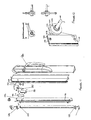
- Figure 11 is an exploded view of the components of the door lifting mechanism of the assembly of Figures 9 and 10;
- Figure 12 shows in a plan, two side and a perspective view the principle assembled components of the door lifting mechanism of Figure 11;
- Figure 13 is a perspective view of the underside of an alternative embodiment of a grille in the form of a tile;
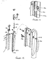
- Figure 14 is a side view of an alternative door lifting mechanism; and
- Figure 15 is an exploded view of the components of the door lifting mechanism of Figure 14.
-
- Figures 1 to 3 illustrates the principle elements of a shower tray 10 in accordance with the present invention. The tray 10 includes a rectangular shower area 11 and
front 12 andside 13 drainage channels along two adjacent edges thereof. The shower area 11 is raised at its rearward edge in order to produce an incline towards the drainage channels. The shower area 11 is divided into twodrainage areas channels backs grille 30 over substantially the entire length of thedrainage channels - The
channels floorboards 25. The depth of the shower tray in the area of the channels is, accordingly, chosen to correspond to the thickness of a standard floorboard such that the bottom surface 22 (in Figure 2) of the tray is supported upon one ormore floor joists 26. Additional support may also be provided to give support to the tray between the joists. For example, the whole area below the shower tray may be excavated and a board put in place to create a continuous and flat surface upon which the tray can sit. - The shower tray has a
drainage hole 23 at one end of a channel, the particular position being chosen such that the associateddrain gully 24 occupies a position between adjacent floor joists. In the embodiment shown in Figure 1, no drainage hole is provided but an enlarged flat area 21 is provided at the end ofside drainage channel 13 for on-site cutting of a drainage hole in an appropriate position to avoid underlying floor joists. Similarly with floors of solid construction such as concrete, a corresponding channel 20 is chased out of the floor, together with the necessary space for thedrainage components 24. - Rather than provide shower trays with two enlarged flat areas 21, it will be appreciated that shower trays in accordance with the present invention will be provided in a range of configurations. For example, when viewed from the front, the
side channel 13 may be on the left or the right hand side and for each of these configurations, the drain may be provided at the end of theside channel 13 or at the end of thefront channel 12. Alternative embodiments can be envisaged such as one in which the drainage hole is provided at the junction of the twochannels - Typically, drainage of water from the tray will be by conventional gravity means. Alternatively, pump-assisted drainage may be provided.
- As is most clearly illustrated in Figure 2, the outer edge of the tray 10 is stepped to provide regions for overlapping floor coverings. Firstly, the tray abuts the
adjacent floor board 25. The tray has a recessed or steppedportion 31 to receive a sheet of waterproofedboard 27 such that the waterproofed board overlaps both thefloorboard 25 and the tray 10. Finally, there is a further steppedportion 32 to receive the final floor covering 28, typically a slip resistant linoleum-type material, such as that sold under the trade mark 'Altro', such that final floor covering 28 overlaps the waterproofedboard 27 and the tray 10. As shown, the shower area 11 of the tray may also be recessed to receive a sheet of matching floor covering 33 although this is not an essential feature. - The features of the drainage channel itself are most clearly illustrated in Figures 1 and 2. As illustrated, the channel has a
first sidewall 40 adjoining the edge of the shower area 11, curving downwardly towards thebase 41 of thechannel 12 and asecond sidewall 43 which may also be curved.First sidewall 40 includes a plurality of arcuate grille-support members 42 projecting outwardly therefrom.Second side wall 43 includes a ledge 44 also acting as a grille support. In an alternative embodiment (not shown), arcuate grille-support members 42 are replaced by a continuous support ledge. A raisedlongitudinal ridge 45 is provided within the channel intermediate sidewalls to provide additional grille support, thereby dividing the drainage channel into two flow channels, a primary flow channel 50 adjacent the showeringarea 14 and asecondary flow channel 51 adjacent the outer edge of the shower tray. As shown, preferably the raisedridge 45 is positioned closer to the outer edge of the shower tray than it is to the showering area, providing a primary flow channel 50 of greater width than the secondary flow channel. - In the preferred embodiment, as is illustrated in Figures 1 and 2, preferably all surfaces over or around which water will flow are arcuate or rounded to encourage a smooth or laminar flow.
- The grille itself will now be described in further detail with particular reference to Figures 5 and 6 which show a section of grille to be positioned at the junction between the two
channels grille 60 includes a plurality oflongitudinal drainage apertures 61 formed inchannels 62 which encourage drainage therethrough. Alternatively, the apertures could be axial or diagonally orientated. As is most clearly seen in Figure 6, the grille is provided with a slight camber to encourage drainage. Thegrille 60 includes downwardly depending inner leg components orledge 63 which engage correspondingledges 64 formed in the arcuategrille support members 42. The grille and arcuate grille support members are dimensioned so as to provide a spacing for drainage between theinner edge 64 of the grille and the first sidewall of the channel. Theinner edge 64 of the grille is also provided with an angled profile to provide a clear drainage pathway from the shower area to the drainage flow channel 50. The underside of thegrille 60 includes anelongate track 65 depending therefrom and being profiled to rest, for support, onridge 45 of the drainage channel. - In the embodiment shown, raised
ridge 45 is discontinuous and includes a number ofoverflow channels 52 to allow fluid communication between the twoflow channels 50,51. In an alternative embodiment, not shown, raisedridge 45 is continuous andelongate track 65 includes discontinuities to provide the desired fluid communication. To ensure adequate flow in this arrangement, typicallyridge 45 will be lower in height than in the embodiment illustrated andelongate track 65 is extended downwardly to contact theridge 45. - As shown in Figure 3, the
grille 30 may be a unitary element. However, preferably, the grille is formed by a number of discrete grille elements. - The upper surface of the grille includes a plurality of
further channels 70, preferably perforated for drainage, which act as running tracks for a sliding door assembly 71 (Figure 4). By ensuring that the door assembly runs in tracks in the grille, the present invention ensures that there is little or no flooding of water outside the shower doors. Any water that may, for example, splash over the top of any shower doors will fall onto that part of the grille outside the doors, draining through the grille and into the distal flow channel. This is a significant advantage of the present invention. - The shower door assembly 71 includes a
long door 80 and ashort door 81 and, by way of example, the operation of the long door will now be described in a more detail.Long door 80 comprises three panels, ahinge panel 82, acentral panel 83 and anend panel 84. Each panel, which may be made of toughened or safety glass or of a polymeric material such as acrylic or polycarbonate, is mounted for slidable movement with respect to each adjacent panel.End panel 84 is held between atop rail 90 andbottom rail 91 both of extruded aluminium and including left end caps 92 andright end caps 94. Mounted in the lower edge ofbottom rail 91 are two wheels 93 which engage theinnermost channel 70 of the grille.Central panel 83 is similarly mounted between top andbottom rails central channel 70 of the grille. Top andbottom rails respective channel 95,96 on the rear face thereof which each receive a respective slider element 100,101 secured to the front face of the end panel. Each slider element 100,101 is restrained to slide within its respective channel by top and bottom end caps 98. End caps 98 include a removable insert 99 having extended legs 99a. In use in position in the end cap, the legs 99a of each insert 99 bear against the respective slider element arresting the sliding movement of theend panel 84 over thecentral panel 83 typically resulting in an overlap between the two panels of several inches, providing a resilient door. However, if the insert is removed, the slider elements are free to move to the end of thechannels 95,96, being restrained only by the end caps themselves. This reduces the overlap between the panels to a minimal amount, useful for cleaning. The sliding action of thecentral panel 83 over thehinge panel 82 is exactly the same. The end panels of the long and short doors are provided with locking means to hold them together in a closed configuration. In this embodiment, tubular elements 105,106 are mounted upon the external vertical edges of the respective end panels. Tubular elements 105,106 include opposing magnetic strip elements which serve to retain the doors when closed and provide a degree of waterproofing. - Once the doors are retracted, in order to allow fully open access to the shower area, the shower doors of the present invention are provided with a hinge mechanism to allow the doors to swing outwardly. However, the doors must also be raised in order to disengage the wheels 93 from the
channels 70 of the grille. In the embodiment shown in Figure 7, this is achieved as follows.Hinge panel 82 is provided with a pillar 119 along its vertical end edge which is adapted to pivot within anintermediate element 120 coupled to awall adjustment element 121 itself slidably mountable within a wall-mountedretaining channel 122.Intermediate element 120 includes means, as shown, in the form of anadditional stub component 123, including means for resiliently receiving a distal end of aBowden cable 124.Bowden cable 124 passes over abar 125 and engages, at its other, proximal end, actuatinghandle 130 which is located for rotational movement within the wall-mountedretaining channel 122. As actuatinghandle 130 is rotated, the proximal end ofBowden cable 124 is pulled downwardly, thus raising the distal end ofBowden cable 124 and with it thestub component 123 and thereby the whole door. With the wheels raised from engagement with the channels of the grille, the door can be swung outwardly. - An alternative lifting mechanism is illustrated in Figures 9 to 12. As before a
tubular pillar 127 is provided on the vertical edge of thehinge panel 82. This cap engages lower and upper hinge plates 125,126 mounted at respective ends of achannel 131 fixedly mounted upon a box-sectionintermediate element 132 which is adapted to slide in a channel 133 of wall-mountedretaining channel 122. Hinge caps 125,126 allow a full pivoting movement ofpillar 120 and thus the doors. Lifting of the doors is achieved as follows. Secured tointermediate element 132 are twoplates Plates hook arm 141 having a hook at its uppermost (as shown) end. The hook ofhook arm 141 engages apivot rod 142 mounted between twopivot discs spindle 145 which engages actuatinghandle 130. Rotation ofhandle 130causes hook arm 141 and thus hook plate 140 to lift via a cam action thereby also raising the doors which are then free to pivot open. Alternative cam action mechanisms will be readily apparent to those skilled in the art. - Such an alternative is illustrated in side view in Figure 14 and in an exploded view in Figure 15. As will be apparent from Figure 15, the construction of this embodiment is broadly similar to that of Figures 11 and 12. However, the hook assembly 140,141,142,144 is replaced by a
cam element 150 operatively mounted uponspindle 145 which engages actuatinghandle 130.Cam element 150 is generally trapezoidal in plan view. Plates 134,135 secured tointermediate element 132 are modified from the embodiment described above by provision of a cut-outportion 151 adapted to engagecam element 150. Plates 134,135 may, of course, be formed from a single component. - As is illustrated in Figure 14, although the feature is equally applicable to any embodiment, preferably a gas strut or
piston 152 is included belowplates - In both cases described above, the doors can also pivot over the shower tray for the purposes of drainage.
- In the embodiment described above, the doors are held in the closed position by means of magnetic strips. In the embodiment shown in Figures 9 and 10, a simple
male cap 150 having a pin depending therefrom mounted on the end cap of one end panel engages a corresponding aperture in a correspondingfemale cap 151 mounted on the end cap of the other end panel. The male and female components can, of course, be reversed with advantageous results in avoiding pooling of water within the cavity of the male cap. - The shower tray of the present invention provides a number of significant advantages over the prior art, in particular the tray of US 5,243,716. For example, the use of a drainage channel around more than one edge of the tray allows the use of lower flow rates, which in turn allows the use of shallower gradients and thus tray depths. Alternatively, it allows the use of increased water flows for the same gradients and depths. As the doors overlap the grille generally centrally, water hitting the door from the shower can drain freely into the channel. There is no pooling or flooding as occurs with existing shower door designs. It also provides a shower tray with true level access on two sides, that is to say, it provides enhanced, open, access, a significant advantage for wheelchair bound users and their carers.
- The shower doors of the present invention provide additional significant advantages to those with disabilities. Users with restricted mobility will tend to lean upon any available surfaces for support. All surfaces in showers designed for the disabled should therefore to be able to bear a significant force, although often such showers are not so designed. The present invention satisfies this requirement in a number of aspects. In particular, in use, lateral movement of the shower doors is resisted to a slight degree by wheels 93 running in the
channels 70 of the grille. The running of the doors in the channels also allows vertical forces exerted on the top of the doors to be transmitted vertically down to the grille and thus to the shower tray. - The tray and grille may be made out of many materials as will be apparent to one skilled in the art. For example, the tray may be made by vacuum forming, preferably from glass reinforced plastics materials or by infusion or resin transfer moulding. The grille may be extruded or moulded, from aluminium, a plastics or resinous materials, optionally reinforced, such as a carbon fibre resin material.
- For certain embodiments, moulding is a preferred method for the production of the grille as it allows the addition of arcuate vanes or flow
directors 110 to the underside surface of the grille (as shown in Figure 13). Such vanes act to direct the flow of water specifically towards the drainage area 21 reducing turbulence and aiding water flow velocity. It will be appreciated that the vanes will be left-handed or right-handed to correspond to the required direction of flow. Typically, thevanes 110 project approximately 5mm below the level of theinner ledge 63. As thechannel 13 slopes downwardly towards thegully 23, the gap between the bottom of the vanes increases from approximately 5mm to around 16-18mm.
Claims (9)
- A shower system comprising a shower tray (10) including a cover grille (30) and at least one retractable shower door assembly (71), wherein the shower tray (10) comprises a generally rectilinear shower area (11) having drainage channels (12,13) along the, in use, front edge thereof and at least one other edge adjacent thereto, the showering area (11) having a floor (14,15) sloping towards the drainage channels(12,13); wherein the drainage channels (12,13) are provided with means to support the cover grille (30) thereover, the cover grille (30) being positioned, shaped and dimensioned to provide an elongate drainage aperture between the shower area edges and the corresponding outer edges of the shower tray, wherein the grille includes elongate channels (70) adapted to receive and support a lower edge of the retractable shower door (71); and wherein each drainage channel (12,13) has a first sidewall (40) adjoining the edge of the shower area (11) and a second sidewall (43) adjoining the edge of the shower tray (10); wherein the first and second sidewalls (40,43) are formed with respective grille-support members (42,44) and wherein a raised longitudinal ridge (45) is provided within the drainage channel (12,13) intermediate the first and second sidewalls, thereby providing an additional support for the cover grille (30) and defining a primary flow channel (50) adjacent the shower area (11) and a secondary flow channel (51) adjacent the edge of the shower tray.
- A shower system as claimed in Claim 1 wherein ridge (45) is formed closer to the second sidewall (43) than to the first sidewall (40).
- A shower system as claimed in Claim 1 or claim 2 wherein the ridge (45) is discontinuous to allow fluid communication between the primary and secondary flow channels (50,51).
- A shower system as claimed in any one of Claims 1 to 3 wherein at least one of the grille-support members (42, 44) associated with the first and second sidewalls (40,43) comprises a plurality of generally arcuate members (42) projecting outwardly from the respective sidewall.
- A shower system as claimed in any preceding claim wherein the shower door assembly (71) comprises two retractable shower doors (80,81) each being mountable upon respective walls adjacent the shower area (11) and being adapted to pivot outwardly from or inwardly over the shower area (11) pivoting at a point substantially adjacent the respective wall, wherein each door comprises a plurality of door panels (82,83,84) which are adapted to run in said elongate channels (70) of said grille (30).
- A shower system as claimed in Claim 5 wherein the door panels (82, 83, 84) are adapted to run in the elongate grille channels (70) by means of runners or wheels (93) being provided in a lower surface (91) of each door panel (82,83,84).
- A shower system as claimed in Claim 5 or Claim 6 wherein each door (80,81) is adapted to pivot outwardly by being provided with a mechanism which includes a lifting mechanism to raise the runners or wheels (93) of each panel (82,83,84) out of engagement with the channels (70) of the grille (30).
- A shower system as claimed in Claim 7 wherein the lifting mechanism includes a cap or pillar (119,127) secured to the edge of that door panel (82) adjacent the pivot point, which cap (119,127) is pivotally mounted upon an intermediate element (120,132) slidably mounted (121,133) within a wall-mountable retaining channel (122); and wherein a hook element (140,141) is mounted on the intermediate element (132) for pivotal movement about a horizontal axis such that a rotational movement of the hook element (140,141) imparts a linear motion to the intermediate element (132) and wherein such pivotal movement is preferably actuated by means of a hook arm (141) in the hook element engaging a rod or pin (142) mounted eccentrically upon a rotatable pivot disc (143, 144).
- A shower system as claimed in any one of Claims 5 to 8 wherein each door comprises at least a first and a second door panel, wherein each panel is mounted between respective top (90) and bottom (91) rails and the first panel includes a respective channel (95,96) on a first face thereof each of which channels (95,96) receives a respective slider element (100,101) secured to the second face of the second panel; wherein each slider element (100,101) is constrained to slide within its respective channel by top and bottom end caps (98) including a retractable insert (99) having extended legs (99a) adapted to bear against a respective slider element (100,101).
Priority Applications (1)
| Application Number | Priority Date | Filing Date | Title |
|---|---|---|---|
| DK01301135T DK1123680T3 (en) | 2000-02-09 | 2001-02-08 | Shower tray and doors |
Applications Claiming Priority (2)
| Application Number | Priority Date | Filing Date | Title |
|---|---|---|---|
| GBGB0002939.7A GB0002939D0 (en) | 2000-02-09 | 2000-02-09 | Shower tray and doors |
| GB0002939 | 2000-02-09 |
Publications (2)
| Publication Number | Publication Date |
|---|---|
| EP1123680A1 EP1123680A1 (en) | 2001-08-16 |
| EP1123680B1 true EP1123680B1 (en) | 2004-12-15 |
Family
ID=9885227
Family Applications (1)
| Application Number | Title | Priority Date | Filing Date |
|---|---|---|---|
| EP01301135A Expired - Lifetime EP1123680B1 (en) | 2000-02-09 | 2001-02-08 | Shower tray and doors |
Country Status (5)
| Country | Link |
|---|---|
| EP (1) | EP1123680B1 (en) |
| AT (1) | ATE284642T1 (en) |
| DE (1) | DE60107726T2 (en) |
| DK (1) | DK1123680T3 (en) |
| GB (1) | GB0002939D0 (en) |
Cited By (1)
| Publication number | Priority date | Publication date | Assignee | Title |
|---|---|---|---|---|
| US11905697B2 (en) | 2020-05-21 | 2024-02-20 | Oatey Co. | Drain assembly and method of installation |
Families Citing this family (2)
| Publication number | Priority date | Publication date | Assignee | Title |
|---|---|---|---|---|
| GB0227920D0 (en) | 2002-11-29 | 2003-01-08 | Esl Healthcare Ltd | Improvements in or relating to shower screens |
| US9433325B2 (en) | 2014-01-28 | 2016-09-06 | Liberty Hardware Mfg. Corp. | Sliding shower door guide and drain assembly |
Family Cites Families (4)
| Publication number | Priority date | Publication date | Assignee | Title |
|---|---|---|---|---|
| DE3600945A1 (en) * | 1985-01-16 | 1986-10-23 | Waldemar 7057 Leutenbach Beutel | Sliding-door means, in particular for a unitized unit |
| DE9101583U1 (en) * | 1991-02-12 | 1992-06-04 | Schwitters, Henry, 2944 Wittmund | Floor part of a shower cubicle |
| US5243716A (en) | 1991-07-17 | 1993-09-14 | Herman Miller, Inc. | Barrier-free drainage apparatus |
| GB9220511D0 (en) | 1992-09-29 | 1992-11-11 | Eastbourne Showers Ltd | Shower tray |
-
2000
- 2000-02-09 GB GBGB0002939.7A patent/GB0002939D0/en not_active Ceased
-
2001
- 2001-02-08 AT AT01301135T patent/ATE284642T1/en not_active IP Right Cessation
- 2001-02-08 EP EP01301135A patent/EP1123680B1/en not_active Expired - Lifetime
- 2001-02-08 DK DK01301135T patent/DK1123680T3/en active
- 2001-02-08 DE DE60107726T patent/DE60107726T2/en not_active Expired - Fee Related
Cited By (1)
| Publication number | Priority date | Publication date | Assignee | Title |
|---|---|---|---|---|
| US11905697B2 (en) | 2020-05-21 | 2024-02-20 | Oatey Co. | Drain assembly and method of installation |
Also Published As
| Publication number | Publication date |
|---|---|
| GB0002939D0 (en) | 2000-03-29 |
| EP1123680A1 (en) | 2001-08-16 |
| ATE284642T1 (en) | 2005-01-15 |
| DE60107726T2 (en) | 2005-12-08 |
| DK1123680T3 (en) | 2005-04-04 |
| DE60107726D1 (en) | 2005-01-20 |
Similar Documents
| Publication | Publication Date | Title |
|---|---|---|
| US8813290B1 (en) | Operable ramp | |
| US8646120B2 (en) | Bathing device, systems and methods | |
| CA2731855A1 (en) | Low profile shower base | |
| US20120079652A1 (en) | Reversible low profile shower base | |
| US5243716A (en) | Barrier-free drainage apparatus | |
| EP1123680B1 (en) | Shower tray and doors | |
| JP3364465B2 (en) | Structure around the bathroom door | |
| GB2352393A (en) | Bath having a door | |
| TWM606364U (en) | Door sheet guide, and barrier-free shower sliding door structure including the same | |
| JPH0828144A (en) | Drain structure | |
| EP4349226A1 (en) | A frame for a shower cubicle, a shower cubicle and a method | |
| AU2006203623A1 (en) | A Modular Bathroom | |
| US20230010114A1 (en) | Retractable shower floor | |
| AU2010226970A1 (en) | Shower base | |
| JP2640925B2 (en) | Substructure of entrance | |
| JP3446511B2 (en) | Bathroom entrance structure | |
| GB2299607A (en) | Drainage unit for door sill | |
| US20130239319A1 (en) | Threshold assembly for barrier free shower units | |
| JPH0220298Y2 (en) | ||
| RU2780668C1 (en) | Floor threshold system for movable sliding or lifting and sliding window or door sash | |
| JP3622815B2 (en) | Bathroom door structure | |
| JP2000303523A (en) | Drainage ditch for bathroom | |
| JP3481053B2 (en) | Door sash | |
| JPH1018379A (en) | Sanitary room, sanitary unit, doorway structure of sanitary room, and waterproof pan | |
| JP3451416B2 (en) | Sliding door frame |
Legal Events
| Date | Code | Title | Description |
|---|---|---|---|
| PUAI | Public reference made under article 153(3) epc to a published international application that has entered the european phase |
Free format text: ORIGINAL CODE: 0009012 |
|
| AK | Designated contracting states |
Kind code of ref document: A1 Designated state(s): AT BE CH CY DE DK ES FI FR GB GR IE IT LI LU MC NL PT SE TR |
|
| AX | Request for extension of the european patent |
Free format text: AL;LT;LV;MK;RO;SI |
|
| 17P | Request for examination filed |
Effective date: 20020208 |
|
| AKX | Designation fees paid |
Free format text: AT BE CH CY DE DK ES FI FR GB GR IE IT LI LU MC NL PT SE TR |
|
| 17Q | First examination report despatched |
Effective date: 20030314 |
|
| GRAP | Despatch of communication of intention to grant a patent |
Free format text: ORIGINAL CODE: EPIDOSNIGR1 |
|
| GRAS | Grant fee paid |
Free format text: ORIGINAL CODE: EPIDOSNIGR3 |
|
| GRAA | (expected) grant |
Free format text: ORIGINAL CODE: 0009210 |
|
| AK | Designated contracting states |
Kind code of ref document: B1 Designated state(s): AT BE CH CY DE DK ES FI FR GB GR IE IT LI LU MC NL PT SE TR |
|
| PG25 | Lapsed in a contracting state [announced via postgrant information from national office to epo] |
Ref country code: IT Free format text: LAPSE BECAUSE OF FAILURE TO SUBMIT A TRANSLATION OF THE DESCRIPTION OR TO PAY THE FEE WITHIN THE PRESCRIBED TIME-LIMIT;WARNING: LAPSES OF ITALIAN PATENTS WITH EFFECTIVE DATE BEFORE 2007 MAY HAVE OCCURRED AT ANY TIME BEFORE 2007. THE CORRECT EFFECTIVE DATE MAY BE DIFFERENT FROM THE ONE RECORDED. Effective date: 20041215 Ref country code: NL Free format text: LAPSE BECAUSE OF FAILURE TO SUBMIT A TRANSLATION OF THE DESCRIPTION OR TO PAY THE FEE WITHIN THE PRESCRIBED TIME-LIMIT Effective date: 20041215 Ref country code: LI Free format text: LAPSE BECAUSE OF FAILURE TO SUBMIT A TRANSLATION OF THE DESCRIPTION OR TO PAY THE FEE WITHIN THE PRESCRIBED TIME-LIMIT Effective date: 20041215 Ref country code: FI Free format text: LAPSE BECAUSE OF FAILURE TO SUBMIT A TRANSLATION OF THE DESCRIPTION OR TO PAY THE FEE WITHIN THE PRESCRIBED TIME-LIMIT Effective date: 20041215 Ref country code: CH Free format text: LAPSE BECAUSE OF FAILURE TO SUBMIT A TRANSLATION OF THE DESCRIPTION OR TO PAY THE FEE WITHIN THE PRESCRIBED TIME-LIMIT Effective date: 20041215 Ref country code: TR Free format text: LAPSE BECAUSE OF FAILURE TO SUBMIT A TRANSLATION OF THE DESCRIPTION OR TO PAY THE FEE WITHIN THE PRESCRIBED TIME-LIMIT Effective date: 20041215 Ref country code: AT Free format text: LAPSE BECAUSE OF FAILURE TO SUBMIT A TRANSLATION OF THE DESCRIPTION OR TO PAY THE FEE WITHIN THE PRESCRIBED TIME-LIMIT Effective date: 20041215 |
|
| REG | Reference to a national code |
Ref country code: CH Ref legal event code: EP Ref country code: GB Ref legal event code: FG4D |
|
| REG | Reference to a national code |
Ref country code: IE Ref legal event code: FG4D |
|
| REF | Corresponds to: |
Ref document number: 60107726 Country of ref document: DE Date of ref document: 20050120 Kind code of ref document: P |
|
| PG25 | Lapsed in a contracting state [announced via postgrant information from national office to epo] |
Ref country code: CY Free format text: LAPSE BECAUSE OF FAILURE TO SUBMIT A TRANSLATION OF THE DESCRIPTION OR TO PAY THE FEE WITHIN THE PRESCRIBED TIME-LIMIT Effective date: 20050208 |
|
| PG25 | Lapsed in a contracting state [announced via postgrant information from national office to epo] |
Ref country code: MC Free format text: LAPSE BECAUSE OF NON-PAYMENT OF DUE FEES Effective date: 20050228 |
|
| PG25 | Lapsed in a contracting state [announced via postgrant information from national office to epo] |
Ref country code: GR Free format text: LAPSE BECAUSE OF FAILURE TO SUBMIT A TRANSLATION OF THE DESCRIPTION OR TO PAY THE FEE WITHIN THE PRESCRIBED TIME-LIMIT Effective date: 20050315 |
|
| REG | Reference to a national code |
Ref country code: SE Ref legal event code: TRGR |
|
| PG25 | Lapsed in a contracting state [announced via postgrant information from national office to epo] |
Ref country code: ES Free format text: LAPSE BECAUSE OF FAILURE TO SUBMIT A TRANSLATION OF THE DESCRIPTION OR TO PAY THE FEE WITHIN THE PRESCRIBED TIME-LIMIT Effective date: 20050326 |
|
| REG | Reference to a national code |
Ref country code: DK Ref legal event code: T3 |
|
| NLV1 | Nl: lapsed or annulled due to failure to fulfill the requirements of art. 29p and 29m of the patents act | ||
| REG | Reference to a national code |
Ref country code: CH Ref legal event code: PL |
|
| PLBE | No opposition filed within time limit |
Free format text: ORIGINAL CODE: 0009261 |
|
| STAA | Information on the status of an ep patent application or granted ep patent |
Free format text: STATUS: NO OPPOSITION FILED WITHIN TIME LIMIT |
|
| 26N | No opposition filed |
Effective date: 20050916 |
|
| ET | Fr: translation filed | ||
| PGFP | Annual fee paid to national office [announced via postgrant information from national office to epo] |
Ref country code: LU Payment date: 20060123 Year of fee payment: 6 |
|
| PGFP | Annual fee paid to national office [announced via postgrant information from national office to epo] |
Ref country code: BE Payment date: 20060207 Year of fee payment: 6 |
|
| PGFP | Annual fee paid to national office [announced via postgrant information from national office to epo] |
Ref country code: DK Payment date: 20060215 Year of fee payment: 6 |
|
| PGFP | Annual fee paid to national office [announced via postgrant information from national office to epo] |
Ref country code: SE Payment date: 20060223 Year of fee payment: 6 |
|
| REG | Reference to a national code |
Ref country code: GB Ref legal event code: 732E |
|
| PGFP | Annual fee paid to national office [announced via postgrant information from national office to epo] |
Ref country code: DE Payment date: 20060329 Year of fee payment: 6 |
|
| PG25 | Lapsed in a contracting state [announced via postgrant information from national office to epo] |
Ref country code: SE Free format text: LAPSE BECAUSE OF NON-PAYMENT OF DUE FEES Effective date: 20070209 |
|
| REG | Reference to a national code |
Ref country code: DK Ref legal event code: EBP |
|
| EUG | Se: european patent has lapsed | ||
| BERE | Be: lapsed |
Owner name: *ESL HEALTHCARE LTD Effective date: 20070228 |
|
| PG25 | Lapsed in a contracting state [announced via postgrant information from national office to epo] |
Ref country code: PT Free format text: LAPSE BECAUSE OF NON-PAYMENT OF DUE FEES Effective date: 20050515 Ref country code: BE Free format text: LAPSE BECAUSE OF NON-PAYMENT OF DUE FEES Effective date: 20070228 |
|
| PG25 | Lapsed in a contracting state [announced via postgrant information from national office to epo] |
Ref country code: DK Free format text: LAPSE BECAUSE OF NON-PAYMENT OF DUE FEES Effective date: 20070228 Ref country code: DE Free format text: LAPSE BECAUSE OF NON-PAYMENT OF DUE FEES Effective date: 20070901 |
|
| PG25 | Lapsed in a contracting state [announced via postgrant information from national office to epo] |
Ref country code: LU Free format text: LAPSE BECAUSE OF NON-PAYMENT OF DUE FEES Effective date: 20070208 |
|
| PGFP | Annual fee paid to national office [announced via postgrant information from national office to epo] |
Ref country code: IE Payment date: 20110117 Year of fee payment: 11 |
|
| PGFP | Annual fee paid to national office [announced via postgrant information from national office to epo] |
Ref country code: FR Payment date: 20110217 Year of fee payment: 11 |
|
| PGFP | Annual fee paid to national office [announced via postgrant information from national office to epo] |
Ref country code: GB Payment date: 20110201 Year of fee payment: 11 |
|
| GBPC | Gb: european patent ceased through non-payment of renewal fee |
Effective date: 20120208 |
|
| REG | Reference to a national code |
Ref country code: IE Ref legal event code: MM4A |
|
| REG | Reference to a national code |
Ref country code: FR Ref legal event code: ST Effective date: 20121031 |
|
| PG25 | Lapsed in a contracting state [announced via postgrant information from national office to epo] |
Ref country code: FR Free format text: LAPSE BECAUSE OF NON-PAYMENT OF DUE FEES Effective date: 20120229 Ref country code: GB Free format text: LAPSE BECAUSE OF NON-PAYMENT OF DUE FEES Effective date: 20120208 Ref country code: IE Free format text: LAPSE BECAUSE OF NON-PAYMENT OF DUE FEES Effective date: 20120208 |