EP1123573B1 - Assembly for cable conduits of workstation furniture - Google Patents
Assembly for cable conduits of workstation furniture Download PDFInfo
- Publication number
- EP1123573B1 EP1123573B1 EP99953820A EP99953820A EP1123573B1 EP 1123573 B1 EP1123573 B1 EP 1123573B1 EP 99953820 A EP99953820 A EP 99953820A EP 99953820 A EP99953820 A EP 99953820A EP 1123573 B1 EP1123573 B1 EP 1123573B1
- Authority
- EP
- European Patent Office
- Prior art keywords
- profiled
- column
- portions
- rear wall
- grooves
- Prior art date
- Legal status (The legal status is an assumption and is not a legal conclusion. Google has not performed a legal analysis and makes no representation as to the accuracy of the status listed.)
- Expired - Lifetime
Links
Images

Classifications
-
- A—HUMAN NECESSITIES
- A47—FURNITURE; DOMESTIC ARTICLES OR APPLIANCES; COFFEE MILLS; SPICE MILLS; SUCTION CLEANERS IN GENERAL
- A47B—TABLES; DESKS; OFFICE FURNITURE; CABINETS; DRAWERS; GENERAL DETAILS OF FURNITURE
- A47B21/00—Tables or desks for office equipment, e.g. typewriters, keyboards
- A47B21/06—Tables or desks for office equipment, e.g. typewriters, keyboards characterised by means for holding, fastening or concealing cables
-
- H—ELECTRICITY
- H02—GENERATION; CONVERSION OR DISTRIBUTION OF ELECTRIC POWER
- H02G—INSTALLATION OF ELECTRIC CABLES OR LINES, OR OF COMBINED OPTICAL AND ELECTRIC CABLES OR LINES
- H02G3/00—Installations of electric cables or lines or protective tubing therefor in or on buildings, equivalent structures or vehicles
- H02G3/02—Details
- H02G3/04—Protective tubing or conduits, e.g. cable ladders or cable troughs
- H02G3/0462—Tubings, i.e. having a closed section
- H02G3/0487—Tubings, i.e. having a closed section with a non-circular cross-section
-
- H—ELECTRICITY
- H02—GENERATION; CONVERSION OR DISTRIBUTION OF ELECTRIC POWER
- H02G—INSTALLATION OF ELECTRIC CABLES OR LINES, OR OF COMBINED OPTICAL AND ELECTRIC CABLES OR LINES
- H02G3/00—Installations of electric cables or lines or protective tubing therefor in or on buildings, equivalent structures or vehicles
- H02G3/02—Details
- H02G3/04—Protective tubing or conduits, e.g. cable ladders or cable troughs
- H02G3/0437—Channels
Definitions
- the invention relates to a kit for cable ducts of a workstation furniture, which consists of several different, composable profile sections, on which molded connection elements on the inside and / or outside or molded.
- Such a kit is known from DE 196 10 347 C1.
- the one on the Fasteners formed on the inside are webs or grooves and serve for fastening cables and internals.
- For connecting the profile sections to the cable duct are complicated on the free longitudinal edges of the profile sections designed connecting and counter-connecting elements.
- the put together Cable channels serve primarily as horizontal channels can be connected at the front with vertical columns of the furniture frame, and have a relatively small recording space.
- the connecting grooves in the side legs of the column connection profile sections and the rear wall profile sections have a T-shaped cross section, and that on the inside of the column connection profile sections and the rear wall profile sections and at least part of the receiving grooves the connection profile sections T-shaped cross section exhibit.
- connection approaches of the connection profile sections provided with holes and by means of screws with the connecting grooves the column connection profile sections and the rear wall profile sections are screwed, then the colliding Profile sections are simply screwed together and the installation of devices in the cable duct is facilitated.
- connection profile section for the cable duct can also be provided that the side legs of the column connection profile sections and the rear wall profile sections in connection receiving grooves leak that is flush with the outside of the side legs complete and that in the opposing grooves at the ends of the side legs of the column connection profile section and rear wall profile section a flexible cover introduced and held therein.
- a positive reception of the column in the column holder of the Column connection profile section is achieved in that the Column connection profile sections on the outside in the end areas of the base leg have molded hollow chamber webs limit the pillar support, and that the facing side walls this hollow chamber webs the column holder to the outside continuously widening and with holding bars facing each other are provided.
- the holding bars make it easy to attach created for the cable duct on the column in that in the Column receptacles can be inserted with the holding bars are held and with hook strips in slots of the facing side walls the column can be attached. This can be done in the longitudinal direction use several holding slides.
- An embodiment is advantageous which is characterized in that the holding slide means Locking screw in the column holder are immovable.
- the holding bars of the holding slides thus defined are in the division of Slots arranged in the column and positioned so that the at the Column-suspended cable duct at several points along its length is held.
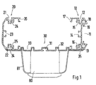
- Fig. 1 form a substantially U-shaped column connection profile section 11 and a substantially U-shaped rear wall profile section 20 the side legs of an open, U-shaped cable duct.
- a connecting profile section 30 forms the base leg of the cable duct.
- the outside of the column connection profile section 10 is with the hollow chamber webs 18 with a column receptacle 11 with molded on Retaining bars 19, in the form-fitting a vertical column 40 of the furniture frame can be introduced, as shown in Fig. 2.
- For fixing holding slides 50 are used, which are behind the holding webs 19 inserted and positioned with locking screws 52.
- the side wall of the column 40 facing the column holder 11 carries a series of horizontal slots 41 into which the hook strips 51 the holding slide 50 can be hooked in if this in the Division of the slots 41 positioned on the column connection profile section 10 are.
- T-shaped connecting grooves 12 and 13 formed in the connecting lugs 34 and 35 of a connecting profile section 30 can be inserted and screwed tight with screws 55, as shown in FIG. 2 shows.
- the connecting grooves 12 and 13 forming profile parts open screw channels 15 and 16 integrally formed, the additional in particular on the end face of the cable duct Offer connection options.
- the side legs of the column connection profile section 10 run in Grooves 17 from. The same applies to the side legs of the in Substantially U-shaped rear wall profile sections 20 with the receiving grooves 26 and the molded connection grooves 21 and 22.
- Die Connection groove 22 takes the connection projection 34 of the connection profile section in FIG. 1 30 on.
- the transitions from the side legs to the base leg of the rear wall profile section 20 beveled.
- the inside of the base leg of the rear wall section 20 carries an integrally formed fastening groove 23, like the base leg of the column connection profile section 10 with the fastening groove 14.
- In the area of the transitions from the side legs to the base leg of the rear wall profile section 20 are open screw channels 24 and 25 integrally molded, the other side fastening options Offer.
- the connecting profile sections 30 are essentially meandering Cross section with alternating on the inside and outside Receiving grooves 31, 32 and 33, for attaching internals and Structures such as Plug strips 80 or the like can be used with cover 81 are.
- a flexible cover 90 which is closed into each other facing receiving grooves 17 and 26 of column connection profile section 10 and rear wall profile section 20 is inserted.
- These flexible Covers can also only cover partial areas of the longitudinal dimension of the cable duct so as to compress the cover at certain points of the cable duct cables in and / or to be able to execute.
- the connecting grooves 12 and 21 of the column connection profile section 10 and the rear wall profile section 20th remain free so that they have grid bars 70 with a number of Can accommodate slots 71. Hooks can be inserted into these slots 71 60 can be hooked in Profile sections of a horizontal cable duct are used. On in this way, horizontal cable channels can be coupled, the Division of the slots 71 in the grid strips 70, the coupling points establish.
- the three different profile sections - column connection, rear wall and Connection profile section - allow the construction of closed and partially open vertical cable channels with a simple and unique mounting option on a vertical column 40 of the Furniture frame.
- connection of the profile sections easily and quickly executable with each other.
- the cable duct offers Attachment and mounting options on its interior and Outsides, in particular the simple coupling of horizontal Cable channels come into play as this is just in use flexible covers in the area of the coupling points the cable routing in the Workplace furniture significantly simplified.
Landscapes
- Engineering & Computer Science (AREA)
- Architecture (AREA)
- Civil Engineering (AREA)
- Structural Engineering (AREA)
- Installation Of Indoor Wiring (AREA)
- Tables And Desks Characterized By Structural Shape (AREA)
- Details Of Indoor Wiring (AREA)
- Rod-Shaped Construction Members (AREA)
- Circuits Of Receivers In General (AREA)
- Insulated Conductors (AREA)
Abstract
Description
Die Erfindung betrifft einen Bausatz für Kabelkanäle eines Arbeitsplatz-Möbels, der aus mehreren unterschiedlichen, zusammensetzbaren Profilabschnitten besteht, an denen auf der Innen- und/oder Außenseite Verbindungselemente angeformt oder eingeformt sind.The invention relates to a kit for cable ducts of a workstation furniture, which consists of several different, composable profile sections, on which molded connection elements on the inside and / or outside or molded.
Ein derartiger Bausatz ist aus der DE 196 10 347 C1 bekannt. Die auf der Innenseite angeformten Verbindungselemente sind Stege oder Nuten und dienen zur Befestigung von Kabeln und Einbauten. Zur Verbindung der Profilabschnitte zum Kabelkanal sind an den freien Längskanten der Profilabschnitte kompliziert gestaltete Verbindungs- und Gegenverbindungselemente angeformt. Die zusammengesteckten Kabelkanäle dienen in erster Linie als Horizontalkanäle, die stirnseitig mit vertikalen Säulen des Möbelgestelles verbindbar sind, und haben einen verhältnismäßig kleinen Aufnahmeraum.Such a kit is known from DE 196 10 347 C1. The one on the Fasteners formed on the inside are webs or grooves and serve for fastening cables and internals. For connecting the profile sections to the cable duct are complicated on the free longitudinal edges of the profile sections designed connecting and counter-connecting elements. The put together Cable channels serve primarily as horizontal channels can be connected at the front with vertical columns of the furniture frame, and have a relatively small recording space.
Es ist Aufgabe der Erfindung, einen Bausatz der eingangs erwähnten Art zu schaffen, mit dem mit einfachen Verbindungselementen versehene Profilabschnitte schnell und einfach Kabelkanäle zusammengesetzt werden können, die an vertikalen Säulen des Möbelgestelles angebracht werden können.It is an object of the invention to provide a kit of the type mentioned to create with the provided with simple fasteners Profile sections can be put together quickly and easily can attached to vertical columns of the furniture frame can be.
Diese Aufgabe wird nach der Erfindung dadurch gelöst, dass der Bausatz
drei verschiedene Profilabschnitte umfaßt:
Mit dem Säulenanschluß-Profilteil wird mit der Säulenaufnahme eine großflächige Anbringung des Kabelkanals an der Säule erreicht, die sich über die gesamte Länge des Kabelkanals erstreckt. Die mit den Verbindungsnuten versehenen Rückwand-Profilabschnitte und Verbindungs-Profilabschnitte können leicht miteinander verbunden werden. Mit den Befestigungsnuten und Aufnahmenuten der Profilabschnitte werden Befestigungs- und Anbringungsmöglichkeiten für Einbauten, Steckerleisten und dgl. auf den Innen- und/oder Außenseiten des zusammengesetzten Kabelkanals geschaffen. Außerdem wird darüber auch das Anbringen von horizontalen Kabelkanälen an dem mit einer Säule verbundenen, vertikalen Kabelkanal erleichtert. Mit vier Profilabschnitten läßt sich ein geschlossener Kabelkanal zusammensetzen, der allen Anforderungen für den Einsatz in einem Arbeitsplatz-Möbel gerecht wird.With the column connection profile part with the column holder Large-area attachment of the cable duct to the column is achieved extends over the entire length of the cable duct. The one with the connecting grooves provided rear wall profile sections and connecting profile sections can be easily connected. With the Fastening grooves and receiving grooves of the profile sections are and mounting options for internals, power strips and the like on the inner and / or outer sides of the composite Cable channel created. In addition, it also attaches of horizontal cable ducts on the vertical connected with a column Cable duct relieved. With four profile sections one can Put together a closed cable duct that meets all requirements for the use in a workplace furniture.
Nach einer bevorzugten Ausgestaltung ist vorgesehen, dass die Verbindungsnuten in den Seitenschenkeln der Säulenanschluß-Profilabschnitte und den Rückwand-Profilabschnitten T-förmigen Querschnitt aufweisen, sowie dass die an den Innenseiten der Säulenanschluß-Profilabschnitte und den Rückwand-Profilabschnitten sowie zumindest ein Teil der Aufnahmenuten der Verbindungs-Profilabschnitte T-förmigen Querschnitt aufweisen.According to a preferred embodiment it is provided that the connecting grooves in the side legs of the column connection profile sections and the rear wall profile sections have a T-shaped cross section, and that on the inside of the column connection profile sections and the rear wall profile sections and at least part of the receiving grooves the connection profile sections T-shaped cross section exhibit.
Ist vorgesehen, dass die Verbindungsansätze der Verbindungs-Profilabschnitte mit Bohrungen versehen und mittels Schrauben mit den Verbindungsnuten der Säulenanschluß-Profilabschnitte und der Rückwand-Profilabschnitte verschraubbar sind, dann können die aufeinander stoßenden Profilabschnitte auf einfache Art miteinander verschraubt werden und der Einbau von Einrichtungen in den Kabelkanal ist erleichtert. It is provided that the connection approaches of the connection profile sections provided with holes and by means of screws with the connecting grooves the column connection profile sections and the rear wall profile sections are screwed, then the colliding Profile sections are simply screwed together and the installation of devices in the cable duct is facilitated.
Weitere Befestigungsmöglichkeiten werden dadurch geschaffen, dass in die Verbindungsnuten der Säulenanschluß-Profilabschnitte und der Rückwand-Profilabschnitte Rasterleisten mit einer Reihe von Schlitzen einschiebbar und unverlierbar darin gehalten sind, und dass in die Schlitze Einhängehaken einhängbar sind, die stirnseitig in Aufnahmenuten von senkrecht dazu stehenden Profilabschnitten eingesetzt sind, sowie dadurch, dass im Bereich der Ver-bindungsnuten der Säulenanschluß-Profilabschnitte und der Rückwand-Profilabschnitte im Inneneckbereich offene Schraubkanäle angeformt sind.Further mounting options are created by the fact that in the connecting grooves of the column connection profile sections and the rear wall profile sections Grid strips can be inserted with a series of slots and held captive in it, and that in the slots Hooks are hooked, the front of the grooves in perpendicular profile sections are used, and thereby that in the area of the connecting grooves of the column connection profile sections and the rear wall profile sections in the inner corner area open screw channels are formed.
Anstelle eines zweiten Verbindungs-Profilabschnittes für den Kabelkanal kann auch vorgesehen sein, dass die Seitenschenkel der Säulenanschluß-Profilabschnitte und der Rückwand-Profilabschnitte in Anschlußaufnahmenuten auslaufen, die bündig mit den Außenseiten der Seitenschenkel abschließen und dass in die gegeneinander gerichteten Aufnahmenuten an den Enden der Seitenschenkel von Säulenanschluß-Profilabschnitt und Rückwand-Profilabschnitt eine flexible Abdeckung eingebracht und darin gehalten ist.Instead of a second connection profile section for the cable duct can also be provided that the side legs of the column connection profile sections and the rear wall profile sections in connection receiving grooves leak that is flush with the outside of the side legs complete and that in the opposing grooves at the ends of the side legs of the column connection profile section and rear wall profile section a flexible cover introduced and held therein.
Eine formschlüssige Aufnahme der Säule in der Säulenaufnahme des Säulenanschluß-Profilabschnittes wird dadurch erreicht, dass die Säulenanschluß-Profilabschnitte auf den Außenseiten in den Endbereichen des Basisschenkels angeformte Hohlkammerstege aufweisen, die die Säulenaufnahme begrenzen, und dass die einander zugekehrten Seitenwände dieser Hohlkammerstege die Säulenaufnahme nach außen kontinuierlich verbreitern und mit gegeneinander gerichteten Haltestegen versehen sind. Mit den Haltestegen wird eine leichte Anbringungsmöglichkeit für den Kabelkanal an der Säule dadurch geschaffen, dass in die Säulenaufnahme Halteschieber einbringbar sind, die mit den Haltestegen gehalten sind und mit Hakenleisten in Schlitze der zugekehrten Seitenwände der Säule einhängbar sind. Dabei lassen sich in Längsrichtung mehrere Halteschieber verwenden. Von Vorteil ist dabei eine Ausgestaltung, die dadurch gekennzeichnet ist, dass die Halteschieber mittels Arretierschraube in der Säulenaufnahme unverschiebbar festlegbar sind. Die Haltestege der so festgelegten Halteschieber sind in der Teilung der Schlitze in der Säule angeordnet und positioniert, so dass der an der Säule eingehängte Kabelkanal an mehreren Stellen seiner Längsabmessung gehalten ist.A positive reception of the column in the column holder of the Column connection profile section is achieved in that the Column connection profile sections on the outside in the end areas of the base leg have molded hollow chamber webs limit the pillar support, and that the facing side walls this hollow chamber webs the column holder to the outside continuously widening and with holding bars facing each other are provided. The holding bars make it easy to attach created for the cable duct on the column in that in the Column receptacles can be inserted with the holding bars are held and with hook strips in slots of the facing side walls the column can be attached. This can be done in the longitudinal direction use several holding slides. An embodiment is advantageous which is characterized in that the holding slide means Locking screw in the column holder are immovable. The holding bars of the holding slides thus defined are in the division of Slots arranged in the column and positioned so that the at the Column-suspended cable duct at several points along its length is held.
Die Erfindung wird anhand von in den Zeichnungen dargestellten Ausführungsbeispielen näher erläutert. Es zeigen:
- Fig. 1
- im Querschnitt einen offenen Kabelkanal, der aus einem Säulenanschluß-Profilabschnitt, einem Rückwand-Profilabschnitt und einem Verbindungs-Profilabschnitt zusammengesetzt ist und
- Fig. 2
- im Querschnitt einen an einer Säule befestigten Kabelkanal, der au einem Säulenanschluß-Profilabschnitt, einem Rückwand-Profilabschnitt, einem Verbindungs-Profilabschnitt und einer flexiblen Abdeckung als zweite Verbindung zwischen dem Säulenanschluß-Profilabschnitt und dem Rückwand-Profilabschnitt dient.
- Fig. 1
- in cross section an open cable duct, which is composed of a column connection profile section, a rear wall profile section and a connection profile section and
- Fig. 2
- in cross section a cable duct fastened to a column, which serves as a second connection between the column connection profile section and the rear wall profile section on a column connection profile section, a rear wall profile section, a connection profile section and a flexible cover.
In Fig. 1 bilden ein im wesentlichen U-förmiger Säulenanschluß-Profilabschnitt
11 und ein im wesentlichen U-förmiger Rückwand-Profilabschnitt
20 die Seitenschenkel eines offenen, U-förmigen Kabelkanals.
Ein Verbindungs-Profilabschnitt 30 bildet den Basisschenkel des Kabelkanals.
Die Außenseite des Säulenanschluß-Profilabschnittes 10 ist mit
den Hohlkammerstegen 18 eine Säulenaufnahme 11 mit angeformten
Haltestegen 19, in die formschlüssig eine vertikale Säule 40 des Möbelgestelles
eingeführt werden kann, wie Fig. 2 erkennen läßt. Zur Befestigung
werden Halteschieber 50 verwendet, die hinter die Haltestege
19 eingeschoben und mit Arretierschrauben 52 positioniert werden können.
Die der Säulenaufnahme 11 zugekehrte Seitenwand der Säule 40
trägt eine Reihe von horizontalen Schlitzen 41, in die die Hakenleisten
51 der Halteschieber 50 eingehängt werden können, wenn diese in der
Teilung der Schlitze 41 an dem Säulenanschluß-Profilabschnitt 10 positioniert
sind.In Fig. 1 form a substantially U-shaped column
In die Außenseiten der Seitenschenkel der Säulenanschluß-Profilabschnitte
10 sind T-förmige Verbindungsnuten 12 und 13 eingeformt, in
die Verbindungsansätze 34 und 35 eines Verbindungs-Profilabschnittes
30 einführbar und mit Schrauben 55 festschraubbar sind, wie Fig. 2
zeigt. In den Übergangsbereichen zwischen Basisschenkel und Seitenschenkel
des Säulenanschluß-Profilabschnittes 10 sind an den die Verbindungsnuten
12 und 13 bildenden Profilteilen offene Schraubkanäle 15
und 16 angeformt, die insbesondere stirnseitig am Kabelkanal zusätzliche
Verbindungsmöglichkeiten bieten.In the outer sides of the side legs of the column
Die Seitenschenkel des Säulenanschluß-Profilabschnittes 10 laufen in
Aufnahmenuten 17 aus. Dasselbe gilt auch für die Seitenschenkel der im
Wesentlichen U-förmigen Rückwand-Profilabschnitte 20 mit den Aufnahmenuten
26 und den eingeformten Verbindungsnuten 21 und 22. Die
Verbindungsnut 22 nimmt in Fig. 1 den Verbindungsansatz 34 des Verbindungs-Profilabschnittes
30 auf. Die Übergänge von den Seitenschenkeln
zu dem Basisschenkel des Rückwand-Profilabschnittes 20 sind
abgeschrägt. Die Innenseite des Basisschenkels des Rückwand-Profilabschnittes
20 trägt eine angeformte Befestigungsnut 23, wie der Basisschenkel
des Säulenanschluß-Profilabschnittes 10 mit der Befestigungsnut
14. Im Bereich der Übergänge von den Seitenschenkeln zum Basisschenkel
des Rückwand-Profilabschnittes 20 sind offene Schraubkanäle
24 und 25 angeformt, die stirnseitig weitere Befestigungsmöglichkeiten
bieten.The side legs of the column
Die Verbindungs-Profilabschnitte 30 haben im Wesentlichen mäanderförmigen
Querschnitt mit auf der Innen- und Außenseite abwechselnden
Aufnahmenuten 31, 32 und 33, die zum Anbringen von Einbauten und
Aufbauten, wie z.B. Steckerleisten 80 oder dgl. mit Abdeckung 81 verwendbar
sind. The connecting
Wie Fig. 2 zeigt, kann die in Fig. 1 offene Seite des Kabelkanals mit
einer flexiblen Abdeckung 90 verschlossen werden, die in die einander
zugekehrten Aufnahmenuten 17 und 26 von Säulenanschluß-Profilabschnitt
10 und Rückwand-Profilabschnitt 20 eingesetzt ist. Diese flexiblen
Abdeckungen können sich auch nur über Teilbereiche der Längsabmessung
des Kabelkanals erstrecken, um so durch Zusammendrücken
der Abdeckung an bestimmten Stellen des Kabelkanals Kabel ein- und/oder
ausführen zu können. Die Verbindungsnuten 12 und 21 des Säulenanschluß-Profilabschnittes
10 und des Rückwand-Profilabschnittes 20
bleiben dabei frei, so dass sie Rasterleisten 70 mit einer Reihe von
Schlitzen 71 aufnehmen können. In diese Schlitze 71 können Einhängehaken
60 eingehängt werden, die stirnseitig in Verbindungsnuten von
Profilabschnitten eines horizontalen Kabelkanals eingesetzt sind. Auf
diese Weise lassen sich horizontale Kabelkanäle ankoppeln, wobei die
Teilung der Schlitze 71 in den Rasterleisten 70 die Ankoppelstellen
festlegen.As shown in FIG. 2, the side of the cable duct that is open in FIG
a
Die drei unterschiedlichen Profilabschnitte - Säulenanschluß-, Rückwandund
Verbindungs-Profilabschnitt - erlauben den Aufbau geschlossener
und teilweise offener vertikale Kabelkanäle mit einer einfachen und
eindeutigen Befestigungsmöglichkeit an einer vertikalen Säule 40 des
Möbelgestelles. Darüber hinaus ist die Verbindung der Profilabschnitte
untereinander einfach und schnell ausführbar. Der Kabelkanal bietet
Anbringungs- und Befestigungsmöglichkeiten auf seinen Innen- und
Außenseiten, wobei insbesondere die einfache Ankopplung von horizontalen
Kabelkanälen ins Gewicht fällt, da dies gerade im Einsatz mit
flexiblen Abdeckungen im Bereich der Koppelstellen die Kabelführung im
Arbeitsplatz-Möbel entscheidend vereinfacht.The three different profile sections - column connection, rear wall and
Connection profile section - allow the construction of closed
and partially open vertical cable channels with a simple and
unique mounting option on a
Claims (13)
- Structural assembly for cable ducts of a workstation, said assembly comprising a plurality of different, interconnectable profiled portions, on which connecting members are moulded or provided on the internal side and/or on the external side, characterised in that it includes three different profiled portions:a) profiled column connecting portions (10) having a substantially U-shaped cross-section, the base member on the external side being in the form of a column receiver (11), connecting grooves (12, 13) being provided in the external sides of the lateral members, and the internal side of the base member being provided with a moulded mounting groove (14),b) profiled rear wall portions (20) having a substantially U-shaped cross-section, the internal side of the base member being provided with a moulded mounting groove (23), and connecting grooves (21, 22) being provided in the external sides of the lateral members, andc) profiled connecting portions (30) having a substantially serpentine-like cross-section for connecting the profiled column connecting portion (10) to the profiled rear wall portion (20), receiver grooves (31, 32, 33) being formed alternately on the internal side and on the external side, and the longitudinal edges extending into connecting extension members (34, 35), which are insertable into the connecting grooves (12,13; 21,22) of the profiled column connecting and rear wall portions (10, 20) and being connectable to said portions.
- Structural assembly according to claim 1, characterised in that the connecting grooves (12, 13, 21, 22) in the lateral members of the profiled column connecting portions (10) and in the profiled rear wall portions (20) have a T-shaped cross-section.
- Structural assembly according to claim 1 or 2, characterised in that the connecting grooves at the internal sides of the profiled column connecting portions (10) and at the profiled rear wall portions (20), as well as at least some of the receiver grooves (31) of the profiled connecting portions (30), have a T-shaped cross-section.
- Structural assembly according to one of claims 1 to 3 characterised in that screw channels (15,16; 24,25), which are open in the internal corner region, are provided in the region of the connecting grooves (12,13; 21,22) of the profiled column connecting portions (10) and of the profiled rear wall portions (20).
- Structural assembly according to one of claims 1 to 4, characterised in that the lateral members of the profiled column connecting portions (10) and of the profiled rear wall portions (20) extend into connecting receiver grooves (17, 26), which terminate flush with the external sides of the lateral members.
- Structural member according to one of claims 1 to 5, characterised in that the transitions from the lateral member to the lateral members of the profiled rear wall portions (20) are chamfered.
- Structural assembly according to one of claims 1 to 6, characterised in that the profiled column connecting portions (10) on the external sides have hollow chamber webs (18), which are provided in the end regions of the base member and define the column receiver (11), and in that the lateral walls of these hollow chamber webs (18), which face each other, widen the column receiver (11) continuously outwardly and are provided with retaining webs (19) which are orientated towards each other.
- Structural assembly according to one of claims 1 to 7, characterised in that retaining slides (50) are insertable into the column receiver (11), said slides being retained by means of the retaining webs (19) and being mountable with hook bars (51) in slots (41) of the facing lateral walls of the column (40).
- Structural assembly according to claim 8, characterised in that the retaining slides (50) are non-displaceably securable in the column receiver (11) by means of stop screw (52).
- Structural assembly according to one of claims 1 to 9, characterised in that the connecting extension members (34, 35) of the profiled connecting portions (30) are provided with bores and are screw-connectable to the connecting grooves (13, 22) of the profiled column connecting portions (10) and of the profiled rear wall portions (20) by means of screws (55).
- Structural assembly according to one of claims 1 to 10, characterised in that locking bars (70), having a row of slots (71) therein, are insertable into the connecting grooves (12, 21) of the profiled column connecting portions (10) and of the profiled rear wall portions (20) and are non-detachably retained therein, and in that retaining hooks (60) are mountable in the slots, which hooks are inserted into the front ends of receiver grooves of profiled portions which extend perpendicularly thereto.
- Structural assembly according to claims 1 to 11, characterised in that a flexible cover (90) is inserted into the receiver grooves (17, 26), which are orientated towards each other, at the ends of the lateral members of the profiled column connecting portion (10) and profiled rear wall portion (20) and is retained therein.
- Structural assembly according to one of claims 1 to 12, characterised in that plug boards (80), appliance installation sockets and the like are mountable on the external side and/or on the internal side of the profiled connecting portions (30) as well as on the internal side of the profiled column connecting and rear wall portions (10 and 20).
Applications Claiming Priority (3)
| Application Number | Priority Date | Filing Date | Title |
|---|---|---|---|
| DE19848511A DE19848511C2 (en) | 1998-10-21 | 1998-10-21 | Kit for cable ducts of a workstation furniture |
| DE19848511 | 1998-10-21 | ||
| PCT/EP1999/007732 WO2000024103A1 (en) | 1998-10-21 | 1999-10-14 | Assembly for cable conduits of workstation furniture |
Publications (2)
| Publication Number | Publication Date |
|---|---|
| EP1123573A1 EP1123573A1 (en) | 2001-08-16 |
| EP1123573B1 true EP1123573B1 (en) | 2002-09-18 |
Family
ID=7885174
Family Applications (1)
| Application Number | Title | Priority Date | Filing Date |
|---|---|---|---|
| EP99953820A Expired - Lifetime EP1123573B1 (en) | 1998-10-21 | 1999-10-14 | Assembly for cable conduits of workstation furniture |
Country Status (9)
| Country | Link |
|---|---|
| US (1) | US6528726B1 (en) |
| EP (1) | EP1123573B1 (en) |
| AT (1) | ATE224594T1 (en) |
| BR (1) | BR9914637A (en) |
| DE (2) | DE19848511C2 (en) |
| DK (1) | DK1123573T3 (en) |
| ES (1) | ES2181485T3 (en) |
| PT (1) | PT1123573E (en) |
| WO (1) | WO2000024103A1 (en) |
Families Citing this family (6)
| Publication number | Priority date | Publication date | Assignee | Title |
|---|---|---|---|---|
| DE10159065A1 (en) * | 2001-12-01 | 2003-06-26 | Pierburg Gmbh | Bracket for electro-pneumatic components |
| US7282650B2 (en) * | 2004-10-14 | 2007-10-16 | Lockheed Martin Corp. | Conduit gland |
| DE102007011141B4 (en) | 2007-03-07 | 2012-10-25 | Elabo Gmbh | Work furniture with cable duct |
| DE102015000289B4 (en) * | 2015-01-17 | 2017-10-12 | Detlef Wittkopp | Cable channel system |
| US9825448B1 (en) * | 2015-07-14 | 2017-11-21 | Clayton Dean VanVolkinburg | Electrical raceway assembly and method of using the same |
| US10383435B1 (en) * | 2018-02-12 | 2019-08-20 | Inscape Corporation | Desking arrangement |
Family Cites Families (11)
| Publication number | Priority date | Publication date | Assignee | Title |
|---|---|---|---|---|
| DE2337628A1 (en) * | 1973-07-24 | 1975-02-06 | Intermercury Finance & Trad | INSTALLATION CHANNEL |
| US4907767A (en) * | 1988-08-12 | 1990-03-13 | Hubbell Incorporated | Stackable modular duct assemblies |
| FR2654561B1 (en) * | 1989-11-15 | 1992-01-24 | Boga Ingenierie | SHEATH FOR PIPES OF DISTRIBUTION SYSTEM, AND PROFILE AND METHOD FOR MOUNTING SUCH A SHEATH. |
| DE4007165C2 (en) * | 1990-03-07 | 1995-11-16 | Kleinhuis Hermann Gmbh | Cable duct, such as parapet duct, device installation duct or the like. |
| DE4012442A1 (en) * | 1990-04-19 | 1991-10-24 | Kleinhuis Hermann Gmbh | SUPPLY CHANNEL FOR ELECTRICAL ENERGY |
| FR2686142B1 (en) * | 1992-01-14 | 1994-04-22 | Mavil | COMBINATION OF SUCCESSIVE SECTION OF PLASTIC CABLE TRAY AND MEANS FOR ASSEMBLING THE SAID SECTION, AND METHOD FOR IMPLEMENTING SUCH A COMBINATION. |
| JP3530654B2 (en) * | 1995-10-03 | 2004-05-24 | Smc株式会社 | Conduit |
| DE19610347C1 (en) * | 1996-03-18 | 1997-04-03 | Lampertz Fab Org | Cable ducting system e.g. for office equipment, particularly computer work stations |
| DE29610947U1 (en) * | 1996-06-24 | 1996-08-22 | Miranda Giovanni | Cable duct profile |
| DE19821069A1 (en) * | 1998-05-12 | 1999-11-18 | Hilti Ag | Bracket for a cable duct |
| US6313405B1 (en) * | 1999-08-31 | 2001-11-06 | Cooper Technologies Company | Cable tray |
-
1998
- 1998-10-21 DE DE19848511A patent/DE19848511C2/en not_active Expired - Fee Related
-
1999
- 1999-10-14 DK DK99953820T patent/DK1123573T3/en active
- 1999-10-14 WO PCT/EP1999/007732 patent/WO2000024103A1/en active IP Right Grant
- 1999-10-14 EP EP99953820A patent/EP1123573B1/en not_active Expired - Lifetime
- 1999-10-14 AT AT99953820T patent/ATE224594T1/en not_active IP Right Cessation
- 1999-10-14 ES ES99953820T patent/ES2181485T3/en not_active Expired - Lifetime
- 1999-10-14 DE DE59902789T patent/DE59902789D1/en not_active Expired - Fee Related
- 1999-10-14 BR BR9914637-1A patent/BR9914637A/en not_active IP Right Cessation
- 1999-10-14 US US09/807,912 patent/US6528726B1/en not_active Expired - Fee Related
- 1999-10-14 PT PT99953820T patent/PT1123573E/en unknown
Also Published As
| Publication number | Publication date |
|---|---|
| BR9914637A (en) | 2001-07-03 |
| US6528726B1 (en) | 2003-03-04 |
| EP1123573A1 (en) | 2001-08-16 |
| WO2000024103A1 (en) | 2000-04-27 |
| DE19848511A1 (en) | 2000-05-04 |
| DE19848511C2 (en) | 2001-05-31 |
| DK1123573T3 (en) | 2002-12-30 |
| ATE224594T1 (en) | 2002-10-15 |
| PT1123573E (en) | 2003-01-31 |
| ES2181485T3 (en) | 2003-02-16 |
| DE59902789D1 (en) | 2002-10-24 |
Similar Documents
| Publication | Publication Date | Title |
|---|---|---|
| EP0939984B1 (en) | Switching cabinet | |
| EP0789944B1 (en) | Frame for a switchgear cabinet | |
| DE10057122B4 (en) | Cable duct system with separate cables for conductors and data transmission conductors | |
| DE4137836C1 (en) | ||
| DE19647727A1 (en) | Frame with multiple mounting levels | |
| DE102007012189B3 (en) | Cables feeding-through device, has clamping units, each with spring-elastic side piece for holding it at ramps in insertion position, where clamping units are disassembled in clamping position, in which side pieces are drawn near each other | |
| DE202006005039U1 (en) | Profile for a luminous wall and luminous wall profile system | |
| EP1123573B1 (en) | Assembly for cable conduits of workstation furniture | |
| DE19851952C1 (en) | Switching cabinet has cable infeed with simple elements provided as kit with simple foam sealing elements that can be rapidly and simply attached to cable infeed elements | |
| EP0792979A1 (en) | Modular cladding system | |
| WO1999007957A1 (en) | Dividing wall especially for exhibition booths | |
| EP0933853B1 (en) | Support for an outlet box flush mounted in a channel | |
| DE19836457C1 (en) | Door system, especially door intercom system | |
| DE2657454A1 (en) | Variable housing framing for electrical equipment - consists of supporting hollow elements with approximately rectangular section, and grooved corner connectors | |
| EP1394915B1 (en) | Cable guide | |
| DE10210439B4 (en) | Small housing for receiving electronic assemblies and components | |
| EP1443617B1 (en) | Support rail arrangement for electrical cabinets | |
| DE10311374B4 (en) | Kit for creating frame assemblies for control cabinets | |
| DE19647781A1 (en) | Mounting unit with a mounting rail | |
| DE10113611B4 (en) | Device for receiving lines | |
| DE10019998C2 (en) | Kit for a mailbox system | |
| DE4301634C2 (en) | Frame made of frame legs for a control cabinet | |
| EP1482185B1 (en) | Fastening structure | |
| DE202023102513U1 (en) | Cable carrier for a distributor room for accommodating cables | |
| DE102006024409A1 (en) | Cable Cradle |
Legal Events
| Date | Code | Title | Description |
|---|---|---|---|
| PUAI | Public reference made under article 153(3) epc to a published international application that has entered the european phase |
Free format text: ORIGINAL CODE: 0009012 |
|
| 17P | Request for examination filed |
Effective date: 20010521 |
|
| AK | Designated contracting states |
Kind code of ref document: A1 Designated state(s): AT BE CH CY DE DK ES FI FR GB GR IE IT LI LU MC NL PT SE |
|
| GRAG | Despatch of communication of intention to grant |
Free format text: ORIGINAL CODE: EPIDOS AGRA |
|
| GRAH | Despatch of communication of intention to grant a patent |
Free format text: ORIGINAL CODE: EPIDOS IGRA |
|
| 17Q | First examination report despatched |
Effective date: 20020315 |
|
| GRAH | Despatch of communication of intention to grant a patent |
Free format text: ORIGINAL CODE: EPIDOS IGRA |
|
| GRAA | (expected) grant |
Free format text: ORIGINAL CODE: 0009210 |
|
| AK | Designated contracting states |
Kind code of ref document: B1 Designated state(s): AT BE CH CY DE DK ES FI FR GB GR IE IT LI LU MC NL PT SE |
|
| PG25 | Lapsed in a contracting state [announced via postgrant information from national office to epo] |
Ref country code: IE Free format text: LAPSE BECAUSE OF FAILURE TO SUBMIT A TRANSLATION OF THE DESCRIPTION OR TO PAY THE FEE WITHIN THE PRESCRIBED TIME-LIMIT Effective date: 20020918 Ref country code: GR Free format text: LAPSE BECAUSE OF FAILURE TO SUBMIT A TRANSLATION OF THE DESCRIPTION OR TO PAY THE FEE WITHIN THE PRESCRIBED TIME-LIMIT Effective date: 20020918 |
|
| REF | Corresponds to: |
Ref document number: 224594 Country of ref document: AT Date of ref document: 20021015 Kind code of ref document: T |
|
| REG | Reference to a national code |
Ref country code: GB Ref legal event code: FG4D Free format text: NOT ENGLISH |
|
| REG | Reference to a national code |
Ref country code: CH Ref legal event code: EP |
|
| REG | Reference to a national code |
Ref country code: CH Ref legal event code: NV Representative=s name: PATENTANWAELTE FELDMANN & PARTNER AG |
|
| REG | Reference to a national code |
Ref country code: IE Ref legal event code: FG4D Free format text: GERMAN |
|
| REF | Corresponds to: |
Ref document number: 59902789 Country of ref document: DE Date of ref document: 20021024 |
|
| PG25 | Lapsed in a contracting state [announced via postgrant information from national office to epo] |
Ref country code: CY Free format text: LAPSE BECAUSE OF FAILURE TO SUBMIT A TRANSLATION OF THE DESCRIPTION OR TO PAY THE FEE WITHIN THE PRESCRIBED TIME-LIMIT Effective date: 20021031 |
|
| PGFP | Annual fee paid to national office [announced via postgrant information from national office to epo] |
Ref country code: ES Payment date: 20021106 Year of fee payment: 4 |
|
| PG25 | Lapsed in a contracting state [announced via postgrant information from national office to epo] |
Ref country code: FI Free format text: LAPSE BECAUSE OF NON-PAYMENT OF DUE FEES Effective date: 20021114 |
|
| PGFP | Annual fee paid to national office [announced via postgrant information from national office to epo] |
Ref country code: SE Payment date: 20021125 Year of fee payment: 4 |
|
| PGFP | Annual fee paid to national office [announced via postgrant information from national office to epo] |
Ref country code: AT Payment date: 20021128 Year of fee payment: 4 |
|
| PGFP | Annual fee paid to national office [announced via postgrant information from national office to epo] |
Ref country code: LU Payment date: 20021129 Year of fee payment: 4 Ref country code: FR Payment date: 20021129 Year of fee payment: 4 |
|
| PGFP | Annual fee paid to national office [announced via postgrant information from national office to epo] |
Ref country code: DE Payment date: 20021212 Year of fee payment: 4 |
|
| REG | Reference to a national code |
Ref country code: DK Ref legal event code: T3 |
|
| PGFP | Annual fee paid to national office [announced via postgrant information from national office to epo] |
Ref country code: BE Payment date: 20030102 Year of fee payment: 4 |
|
| PG25 | Lapsed in a contracting state [announced via postgrant information from national office to epo] |
Ref country code: DK Free format text: LAPSE BECAUSE OF NON-PAYMENT OF DUE FEES Effective date: 20030131 |
|
| REG | Reference to a national code |
Ref country code: PT Ref legal event code: SC4A Free format text: AVAILABILITY OF NATIONAL TRANSLATION Effective date: 20021209 |
|
| GBT | Gb: translation of ep patent filed (gb section 77(6)(a)/1977) |
Effective date: 20030116 |
|
| REG | Reference to a national code |
Ref country code: ES Ref legal event code: FG2A Ref document number: 2181485 Country of ref document: ES Kind code of ref document: T3 |
|
| ET | Fr: translation filed | ||
| PG25 | Lapsed in a contracting state [announced via postgrant information from national office to epo] |
Ref country code: MC Free format text: LAPSE BECAUSE OF NON-PAYMENT OF DUE FEES Effective date: 20030501 |
|
| REG | Reference to a national code |
Ref country code: IE Ref legal event code: FD4D Ref document number: 1123573E Country of ref document: IE |
|
| PLBE | No opposition filed within time limit |
Free format text: ORIGINAL CODE: 0009261 |
|
| STAA | Information on the status of an ep patent application or granted ep patent |
Free format text: STATUS: NO OPPOSITION FILED WITHIN TIME LIMIT |
|
| REG | Reference to a national code |
Ref country code: DK Ref legal event code: EBP |
|
| 26N | No opposition filed |
Effective date: 20030619 |
|
| PG25 | Lapsed in a contracting state [announced via postgrant information from national office to epo] |
Ref country code: LU Free format text: LAPSE BECAUSE OF NON-PAYMENT OF DUE FEES Effective date: 20031014 Ref country code: GB Free format text: LAPSE BECAUSE OF NON-PAYMENT OF DUE FEES Effective date: 20031014 Ref country code: AT Free format text: LAPSE BECAUSE OF NON-PAYMENT OF DUE FEES Effective date: 20031014 |
|
| PG25 | Lapsed in a contracting state [announced via postgrant information from national office to epo] |
Ref country code: SE Free format text: LAPSE BECAUSE OF NON-PAYMENT OF DUE FEES Effective date: 20031015 Ref country code: ES Free format text: LAPSE BECAUSE OF NON-PAYMENT OF DUE FEES Effective date: 20031015 |
|
| PG25 | Lapsed in a contracting state [announced via postgrant information from national office to epo] |
Ref country code: LI Free format text: LAPSE BECAUSE OF NON-PAYMENT OF DUE FEES Effective date: 20031031 Ref country code: CH Free format text: LAPSE BECAUSE OF NON-PAYMENT OF DUE FEES Effective date: 20031031 Ref country code: BE Free format text: LAPSE BECAUSE OF NON-PAYMENT OF DUE FEES Effective date: 20031031 |
|
| BERE | Be: lapsed |
Owner name: OTTO *LAMPERTZ G.M.B.H. & CO. K.G. Effective date: 20031031 |
|
| PG25 | Lapsed in a contracting state [announced via postgrant information from national office to epo] |
Ref country code: PT Free format text: LAPSE BECAUSE OF NON-PAYMENT OF DUE FEES Effective date: 20040430 |
|
| PG25 | Lapsed in a contracting state [announced via postgrant information from national office to epo] |
Ref country code: NL Free format text: LAPSE BECAUSE OF NON-PAYMENT OF DUE FEES Effective date: 20040501 Ref country code: DE Free format text: LAPSE BECAUSE OF NON-PAYMENT OF DUE FEES Effective date: 20040501 |
|
| EUG | Se: european patent has lapsed | ||
| GBPC | Gb: european patent ceased through non-payment of renewal fee |
Effective date: 20031014 |
|
| REG | Reference to a national code |
Ref country code: CH Ref legal event code: PL |
|
| NLV4 | Nl: lapsed or anulled due to non-payment of the annual fee |
Effective date: 20040501 |
|
| REG | Reference to a national code |
Ref country code: PT Ref legal event code: MM4A Free format text: LAPSE DUE TO NON-PAYMENT OF FEES Effective date: 20040430 |
|
| PG25 | Lapsed in a contracting state [announced via postgrant information from national office to epo] |
Ref country code: FR Free format text: LAPSE BECAUSE OF NON-PAYMENT OF DUE FEES Effective date: 20041029 |
|
| REG | Reference to a national code |
Ref country code: FR Ref legal event code: ST |
|
| REG | Reference to a national code |
Ref country code: ES Ref legal event code: FD2A Effective date: 20031015 |
|
| PG25 | Lapsed in a contracting state [announced via postgrant information from national office to epo] |
Ref country code: IT Free format text: LAPSE BECAUSE OF NON-PAYMENT OF DUE FEES Effective date: 20051014 |
|
| PG25 | Lapsed in a contracting state [announced via postgrant information from national office to epo] |
Ref country code: PT Free format text: LAPSE BECAUSE OF NON-PAYMENT OF DUE FEES Effective date: 20021014 |
|
| PG25 | Lapsed in a contracting state [announced via postgrant information from national office to epo] |
Ref country code: FR Free format text: LAPSE BECAUSE OF NON-PAYMENT OF DUE FEES Effective date: 20031031 |