EP1123150B1 - Liquid separator for a liquid injected compressor - Google Patents
Liquid separator for a liquid injected compressor Download PDFInfo
- Publication number
- EP1123150B1 EP1123150B1 EP99933332A EP99933332A EP1123150B1 EP 1123150 B1 EP1123150 B1 EP 1123150B1 EP 99933332 A EP99933332 A EP 99933332A EP 99933332 A EP99933332 A EP 99933332A EP 1123150 B1 EP1123150 B1 EP 1123150B1
- Authority
- EP
- European Patent Office
- Prior art keywords
- separator
- tubular
- oil
- coarse
- liquid
- Prior art date
- Legal status (The legal status is an assumption and is not a legal conclusion. Google has not performed a legal analysis and makes no representation as to the accuracy of the status listed.)
- Expired - Lifetime
Links
- 239000007788 liquid Substances 0.000 title claims description 23
- 239000000463 material Substances 0.000 claims description 11
- 239000000835 fiber Substances 0.000 claims description 8
- 238000001816 cooling Methods 0.000 claims description 4
- 230000002745 absorbent Effects 0.000 claims 1
- 239000002250 absorbent Substances 0.000 claims 1
- 239000004744 fabric Substances 0.000 description 7
- 239000003507 refrigerant Substances 0.000 description 7
- 230000035699 permeability Effects 0.000 description 5
- 238000009834 vaporization Methods 0.000 description 3
- LVGUZGTVOIAKKC-UHFFFAOYSA-N 1,1,1,2-tetrafluoroethane Chemical compound FCC(F)(F)F LVGUZGTVOIAKKC-UHFFFAOYSA-N 0.000 description 2
- 229920003235 aromatic polyamide Polymers 0.000 description 2
- 239000012530 fluid Substances 0.000 description 2
- 230000009467 reduction Effects 0.000 description 2
- 238000000926 separation method Methods 0.000 description 2
- 239000010964 304L stainless steel Substances 0.000 description 1
- 241000531908 Aramides Species 0.000 description 1
- OKTJSMMVPCPJKN-UHFFFAOYSA-N Carbon Chemical compound [C] OKTJSMMVPCPJKN-UHFFFAOYSA-N 0.000 description 1
- 229920000271 Kevlar® Polymers 0.000 description 1
- 239000004952 Polyamide Substances 0.000 description 1
- 230000009286 beneficial effect Effects 0.000 description 1
- 229910052799 carbon Inorganic materials 0.000 description 1
- 230000008859 change Effects 0.000 description 1
- 238000010276 construction Methods 0.000 description 1
- 230000001419 dependent effect Effects 0.000 description 1
- 239000004761 kevlar Substances 0.000 description 1
- 238000005259 measurement Methods 0.000 description 1
- 238000000034 method Methods 0.000 description 1
- 239000003595 mist Substances 0.000 description 1
- 238000012986 modification Methods 0.000 description 1
- 230000004048 modification Effects 0.000 description 1
- 229920002647 polyamide Polymers 0.000 description 1
- 230000008569 process Effects 0.000 description 1
Images
Classifications
-
- B—PERFORMING OPERATIONS; TRANSPORTING
- B01—PHYSICAL OR CHEMICAL PROCESSES OR APPARATUS IN GENERAL
- B01D—SEPARATION
- B01D17/00—Separation of liquids, not provided for elsewhere, e.g. by thermal diffusion
- B01D17/02—Separation of non-miscible liquids
-
- F—MECHANICAL ENGINEERING; LIGHTING; HEATING; WEAPONS; BLASTING
- F04—POSITIVE - DISPLACEMENT MACHINES FOR LIQUIDS; PUMPS FOR LIQUIDS OR ELASTIC FLUIDS
- F04C—ROTARY-PISTON, OR OSCILLATING-PISTON, POSITIVE-DISPLACEMENT MACHINES FOR LIQUIDS; ROTARY-PISTON, OR OSCILLATING-PISTON, POSITIVE-DISPLACEMENT PUMPS
- F04C29/00—Component parts, details or accessories of pumps or pumping installations, not provided for in groups F04C18/00 - F04C28/00
- F04C29/02—Lubrication; Lubricant separation
- F04C29/026—Lubricant separation
-
- B—PERFORMING OPERATIONS; TRANSPORTING
- B01—PHYSICAL OR CHEMICAL PROCESSES OR APPARATUS IN GENERAL
- B01D—SEPARATION
- B01D29/00—Filters with filtering elements stationary during filtration, e.g. pressure or suction filters, not covered by groups B01D24/00 - B01D27/00; Filtering elements therefor
- B01D29/50—Filters with filtering elements stationary during filtration, e.g. pressure or suction filters, not covered by groups B01D24/00 - B01D27/00; Filtering elements therefor with multiple filtering elements, characterised by their mutual disposition
-
- F—MECHANICAL ENGINEERING; LIGHTING; HEATING; WEAPONS; BLASTING
- F25—REFRIGERATION OR COOLING; COMBINED HEATING AND REFRIGERATION SYSTEMS; HEAT PUMP SYSTEMS; MANUFACTURE OR STORAGE OF ICE; LIQUEFACTION SOLIDIFICATION OF GASES
- F25B—REFRIGERATION MACHINES, PLANTS OR SYSTEMS; COMBINED HEATING AND REFRIGERATION SYSTEMS; HEAT PUMP SYSTEMS
- F25B43/00—Arrangements for separating or purifying gases or liquids; Arrangements for vaporising the residuum of liquid refrigerant, e.g. by heat
- F25B43/02—Arrangements for separating or purifying gases or liquids; Arrangements for vaporising the residuum of liquid refrigerant, e.g. by heat for separating lubricants from the refrigerant
Definitions
- the present invention relates to a liquid separator arrangement for use with a liquid injected compressor, particularly, but not exclusively, to an oil separator arrangement for an oil-injected helical screw compressor.
- the document GB-A-2063097 describes an oil mist separator comprising several concentric tubular filter elements.
- the liquid separator arrangement has the characteristic features set forth in the accompanying Claim 1.
- the liquid separator arrangement has two separation stages that include an inner, coarse separator and a fine separator which is positioned radially outwards of the coarse separator and through which gas that contains liquid droplets passes radially outwards via an intermediate free space in which the gas flow is able to stop slightly prior to flowing into the fine separator.
- Oil carry-over values as low as 0 to 0.6 percent have been measured with an oil separator arrangement of this construction.
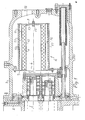
- Figures 1 is a longitudinal sectional view of a selected exemplifying embodiment of an inventive oil separator arrangement mounted on the high pressure end-wall of a helical screw compressor, part of the compressor also being shown in longitudinal section; and
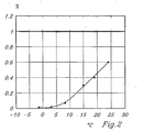
- Figure 2 is a graph which shows the percentage of oil carried over from the oil separator shown in Figure 1, as a function of the vaporisation temperature of the refrigerant.
- a high pressure part of a helical screw cooling compressor is designated 1 and its high pressure end-wall is designated 2.
- the end-wall 2 has mounted thereon a housing 3 which houses an oil separator arrangement 4 constructed in accordance with the invention.
- the compressor 1 has an outlet passageway or duct 5 positioned centrally opposite an inlet opening 6 leading to the oil separator arrangement 4.
- the oil separator arrangement 4 has a vertical, first end-wall 7 which includes an inlet opening 6 in the end thereof proximal to the compressor 1.
- One end of a first perforated sleeve 12 is fastened, e.g. welded; to the periphery of the opening 6.
- the centre line of the sleeve 12 is essentially horizontal.
- the other end of the first sleeve 12 is closed by a disc-shaped member 13.
- a second perforated sleeve 14 is placed outwardly of and concentrically with the first sleeve 12.
- the end of the sleeve 14 that faces towards the compressor is inserted in a circular groove in the end-wall 7.
- a coarse separator 9 is provided in the space formed between said perforated sleeves 12, 14, said sleeves forming walls that hold the coarse separator in place.
- the illustrated liquid separator arrangement 4 also includes a fine separator 10 disposed between mutually spaced and mutually concentric perforated sleeves, a third sleeve 16 and a fourth sleeve 17, outside the third sleeve 16.
- the fine separator 10 including said sleeves 16 and 17 is located outwardly of the coarse separator 9 and in spaced relationship therewith.
- a cavity 11 is defined between the coarse separator 9 and the fine separator 10. The first ends of sleeves 16 and 17 are received in grooves in the first end-wall 7.
- the liquid separator 4 also includes a second end-wall 8, which is parallel and concentrical with the disc plate 13.
- the end-wall 8 includes grooves into which the second, third and fourth sleeves 14, 16 and 17 are inserted and held in place by a bolt and nut joint, 15, said bolt being inserted through openings in the second end-wall 8 and in the centre of the disc plate 13. All of the four perforated sleeves 12, 14, 16 and 17 have a perforated area that exceeds 50 percent of the sleeve area.
- the coarse separator 9 may be a spun wire net, e.g. a "Becoil Demister Mech: 304 L stainless steel type H", said net being applied in a number of layers that together provide a thickness of 2.5 to 3.5 cm.
- the net is wound with a hardness or compactness such that the calculated rate of gas flow will not be less than 0.2 metre per second and not higher than 0.5 metre per second.
- This filter constitutes a first part of the oil separating process and separates the major part of the oil flow (80-90 %) from the system.
- the net layer is held in place with the intended degree of compactness by the first and the second sleeve 12 and 14, these sleeves having a perforated area which exceeds 50 percent of the area of the sleeve surface.
- the holes in the sleeves have a diameter of 8-10 mm.
- the fine separator 10 which is held in place by the third sleeve 16 and the fourth sleeve 17, is comprised of a porous fabric made of oil-resistant and oil-repelling fibres.
- the fabric is wound loosely around the third perforated sleeve 16, to a thickness of 6-8 mm.
- the layer of fibre fabric In order to be able to drain-off oil separated in the coarse separator 9 and also to form an effective separator for the finely divided oil remaining in the fluid flow exiting from the coarse separator 9, it is necessary for the layer of fibre fabric to have a determined porosity, which is determined by the weight per unit area of the fabric layer.
- the fabric layer will have a weight per unit area of 130-170 grams per square metre of fabric having a thickness of 1 millimetre.
- said material may comprise a polyamide fibre material or some corresponding material.
- the material used will conveniently be a carbon fibre or aramide fibre material, preferably a para-aramide material (KEVLAR, trade name for para-amide fibres, owner DU PONT, U.S.A.).
- refrigerant e.g. R134a (tetrafluoroethane, CF 3 CFH 2 ) containing oil in larger or small droplets, down to mist-size, exits from the outlet passageway 5 of the compressor and enters through the inlet opening of the oil separator arrangement 4 at a rate of flow of about 6 metres per second, or at a higher rate.
- R134a tetrafluoroethane
- CF 3 CFH 2 tetrafluoroethane
- the sleeve 14 thus functions as a collecting surface for the oil that is extracted by the coarse separator and that runs down from the lower part thereof.
- the oil that drains from the coarse separator is collected in the lower part of the cavity 11 outside the sleeve 14.
- the cavity 11 has a radial extension of about 1.5 to 2.5 cm.
- the oil that runs from the coarse separator fills a bottom segment of the cavity 11, corresponding to 60 to 90°, and then drains through the outer, fine separator 10.
- the inner limitation of the fine separator forms the outer limitation of the cavity or space 11.
- Oil separated by the coarse separator 9 and collecting on the lowermost part of the fine separator 10 is drained through the lower segmental part of the fibre cloth, this oil-draining segmental part of said separator 10 corresponding to from 60 to 90° of the cylindrical periphery of said separator 10, while the remaining 270-300° of the periphery forms the oil separating area of the fine separator over which remaining, finely-divided oil is extracted from the refrigerant.
- the oil level In order for the oil separator arrangement to operate effectively and to achieve a balance with respect to gas throughflow and oil throughflow, the oil level must only take-up at most 25 percent of the area of the fine separator 10, i.e. the segment may not exceed 90°. Neither will the rate of gas flow through the fine separator 10 be less than 0.1 metre per second.
- the numerical values can be varied depending on different operating conditions, and all or some of the sleeves 12, 14 and 16, 17 can be replaced with rigid net structures of corresponding permeability.
- the permeability of such a rigid net structure may be greater than the permeability of the perforated sleeves, although in this case the greater permeability of said rigid net structure will conveniently be compensated for by a lower permeability of the enclosed coarse-separating and fine-separating materials respectively.
- the separator sleeves may be a cross-sectional shape other than circular, such as a square shape, a pentagonal shape, and so on.
- the sleeves may also taper.
Landscapes
- Engineering & Computer Science (AREA)
- Chemical & Material Sciences (AREA)
- Chemical Kinetics & Catalysis (AREA)
- Mechanical Engineering (AREA)
- General Engineering & Computer Science (AREA)
- Physics & Mathematics (AREA)
- Thermal Sciences (AREA)
- Applications Or Details Of Rotary Compressors (AREA)
- Filtering Of Dispersed Particles In Gases (AREA)
- Compressor (AREA)
Description
- The present invention relates to a liquid separator arrangement for use with a liquid injected compressor, particularly, but not exclusively, to an oil separator arrangement for an oil-injected helical screw compressor.
- The document GB-A-2063097 describes an oil mist separator comprising several concentric tubular filter elements.
- Present-day liquid separators that are fitted directly to the outlet passageway of a compressor have a relatively poor efficiency and often have an oil carry-over of between 3.5 to 4.5 percent, in the best of cases a carry-over of between 2 to 3 percent. Even this latter value is unsuitably high and a reduction to lower values would be beneficial.
- Such reduction has been made possible by means of a liquid separator arrangement that has the characteristic features set forth in the accompanying Claim 1. As will be apparent from the Claim, the liquid separator arrangement has two separation stages that include an inner, coarse separator and a fine separator which is positioned radially outwards of the coarse separator and through which gas that contains liquid droplets passes radially outwards via an intermediate free space in which the gas flow is able to stop slightly prior to flowing into the fine separator. Oil carry-over values as low as 0 to 0.6 percent have been measured with an oil separator arrangement of this construction.
- Particularly suitable embodiments of the liquid separator arrangement for achieving these low carry-over values have the characteristic features set forth in the accompanying dependent Claims.
- The invention will now be described in more detail with reference to the accompanying drawings, in which
- Figures 1 is a longitudinal sectional view of a selected exemplifying embodiment of an inventive oil separator arrangement mounted on the high pressure end-wall of a helical screw compressor, part of the compressor also being shown in longitudinal section; and
- Figure 2 is a graph which shows the percentage of oil carried over from the oil separator shown in Figure 1, as a function of the vaporisation temperature of the refrigerant.
- In Figure 1, a high pressure part of a helical screw cooling compressor is designated 1 and its high pressure end-wall is designated 2. The end-
wall 2 has mounted thereon a housing 3 which houses anoil separator arrangement 4 constructed in accordance with the invention. The compressor 1 has an outlet passageway orduct 5 positioned centrally opposite an inlet opening 6 leading to theoil separator arrangement 4. Theoil separator arrangement 4 has a vertical, first end-wall 7 which includes an inlet opening 6 in the end thereof proximal to the compressor 1. One end of a first perforatedsleeve 12 is fastened, e.g. welded; to the periphery of the opening 6. The centre line of thesleeve 12 is essentially horizontal. The other end of thefirst sleeve 12 is closed by a disc-shaped member 13. A secondperforated sleeve 14 is placed outwardly of and concentrically with thefirst sleeve 12. The end of thesleeve 14 that faces towards the compressor is inserted in a circular groove in the end-wall 7. A coarse separator 9 is provided in the space formed between saidperforated sleeves - The illustrated
liquid separator arrangement 4 also includes afine separator 10 disposed between mutually spaced and mutually concentric perforated sleeves, athird sleeve 16 and afourth sleeve 17, outside thethird sleeve 16. Thefine separator 10 including saidsleeves cavity 11 is defined between the coarse separator 9 and thefine separator 10. The first ends ofsleeves - The
liquid separator 4 also includes a second end-wall 8, which is parallel and concentrical with thedisc plate 13. The end-wall 8 includes grooves into which the second, third andfourth sleeves disc plate 13. All of the fourperforated sleeves - The coarse separator 9 may be a spun wire net, e.g. a "Becoil Demister Mech: 304 L stainless steel type H", said net being applied in a number of layers that together provide a thickness of 2.5 to 3.5 cm. The net is wound with a hardness or compactness such that the calculated rate of gas flow will not be less than 0.2 metre per second and not higher than 0.5 metre per second. This filter constitutes a first part of the oil separating process and separates the major part of the oil flow (80-90 %) from the system. The net layer is held in place with the intended degree of compactness by the first and the
second sleeve - The
fine separator 10, which is held in place by thethird sleeve 16 and thefourth sleeve 17, is comprised of a porous fabric made of oil-resistant and oil-repelling fibres. The fabric is wound loosely around the thirdperforated sleeve 16, to a thickness of 6-8 mm. In order to be able to drain-off oil separated in the coarse separator 9 and also to form an effective separator for the finely divided oil remaining in the fluid flow exiting from the coarse separator 9, it is necessary for the layer of fibre fabric to have a determined porosity, which is determined by the weight per unit area of the fabric layer. According to the invention, the fabric layer will have a weight per unit area of 130-170 grams per square metre of fabric having a thickness of 1 millimetre. In the case of typical temperatures of the oil that comes into contact with the fibre material, said material may comprise a polyamide fibre material or some corresponding material. In the case of higher oil temperatures, the material used will conveniently be a carbon fibre or aramide fibre material, preferably a para-aramide material (KEVLAR, trade name for para-amide fibres, owner DU PONT, U.S.A.). - When the cooling compressor 1 is in operation, refrigerant, e.g. R134a (tetrafluoroethane, CF3CFH2) containing oil in larger or small droplets, down to mist-size, exits from the
outlet passageway 5 of the compressor and enters through the inlet opening of theoil separator arrangement 4 at a rate of flow of about 6 metres per second, or at a higher rate. Because thedisc plate 13 at the end of thefirst sleeve 12 opposite the inlet opening 6 prevents continued flow parallel with the sleeve, the refrigerant flow will change direction and continue radially outwards through the openings or perforations in thefirst sleeve 12. The refrigerant will flow radially through the coarse separator 9 and out through thesecond sleeve 14. - Most of the oil droplets will fasten on the coarse separator net and on the surfaces of the sleeves, and will run down therefrom and leave the coarse separator 9 through the lowermost openings or perforations in the outer tube or
sleeve 14. The oil-depleted refrigerant continues to flow radially outwards through thefine separator 10, where most of the remaining oil is separated from the fluid flow. - The
sleeve 14 thus functions as a collecting surface for the oil that is extracted by the coarse separator and that runs down from the lower part thereof. The oil that drains from the coarse separator is collected in the lower part of thecavity 11 outside thesleeve 14. Thecavity 11 has a radial extension of about 1.5 to 2.5 cm. The oil that runs from the coarse separator fills a bottom segment of thecavity 11, corresponding to 60 to 90°, and then drains through the outer,fine separator 10. The inner limitation of the fine separator forms the outer limitation of the cavity orspace 11. - Oil separated by the coarse separator 9 and collecting on the lowermost part of the
fine separator 10 is drained through the lower segmental part of the fibre cloth, this oil-draining segmental part of saidseparator 10 corresponding to from 60 to 90° of the cylindrical periphery ofsaid separator 10, while the remaining 270-300° of the periphery forms the oil separating area of the fine separator over which remaining, finely-divided oil is extracted from the refrigerant. In order for the oil separator arrangement to operate effectively and to achieve a balance with respect to gas throughflow and oil throughflow, the oil level must only take-up at most 25 percent of the area of thefine separator 10, i.e. the segment may not exceed 90°. Neither will the rate of gas flow through thefine separator 10 be less than 0.1 metre per second. - The reason why this improved separation of the liquid-carried gas is achieved by the invention is difficult to explain, since it is difficult to study the passage of the liquid droplets through the coarse and
fine separators 9, 10. The curve showing the oil carry-over, i.e. the oil that accompanies the gas, shown in Figure 2, was obtained by carrying out measurements on a cooling compressor while using the refrigerant R134a. Figure 2 shows the concentration in weight percent of the oil that accompanies the gaseous refrigerant as a function of its vaporisation temperature. When running the same compressor with a conventionally arranged oil separator in the form of a vertical, wire net plate, an oil carry-over of 3-10 percent was obtained, this variation in percentage depending on the vaporisation temperature. - It will be understood that the invention is not restricted to the illustrated and described exemplifying embodiment thereof, and that modifications can be made in several ways within the scope of the invention defined in the following Claims. For instance, the numerical values can be varied depending on different operating conditions, and all or some of the
sleeves
Claims (9)
- A liquid separator arrangement for a liquid-injected compressor, particularly an oil separator arrangement for an oil-injected helical screw cooling compressor, characterised in that the liquid separator arrangement is located between two end-walls (7, 8) and includes an inner, tubular coarse separator (9) and an outer, tubular fine separator (10) wherein said tubular separators are mutually spaced so as to form an interspace (11) therebetween, and wherein one end-wall (7) includes an opening (6) which connects the internal, tubular area of the coarse separator (9) with a compressed gas outlet passageway (5) in the compressor (1), and wherein the coarse separator (9) and the fine separator (10) are made of a gas and oil permeable material.
- A liquid separator arrangement according to Claim 1, characterised in that the coarse separator (9) includes a net layer.
- A liquid separator arrangement according to Claim 2, characterised in that the net is disposed on a tubular inner wall which includes many openings and which constitutes the inner limitation of the coarse separator.
- A liquid separator arrangement according to Claim 2 or 3, characterised in that the coarse separator (9) has a tubular outer wall that includes many openings whose total area corresponds to at least 50 percent of the total wall area.
- A liquid separator arrangement according to one or more of Claims 1-4, characterised in that the fine separator (10) includes a porous fibre material, the fibres of which are non-absorbent with respect to oil.
- A liquid separator arrangement according to Claim 5, characterised in that the fibre material is disposed between a tubular perforated inner wall and a similar perforated outer wall.
- A liquid separator arrangement according to Claim 6, characterised in that respective tubular walls (12, 14; 16, 17) of the coarse separator (9) and the fine separator (10) are mounted between the end-walls (7, 8) with the ends of said tubular walls (12, 14; 16, 17) guided in grooves on the inner surface of respective end-walls.
- A liquid separator arrangement according to one or more of Claims 1-7, characterised in that the arrangement is dimensioned for a gas flow rate of 0.2-0.5 metre per second through said coarse separator (9).
- A liquid separator arrangement according to one or more of Claims 1-7, characterised in that the separator arrangement is dimensioned so that the rate of gas flow through the fine separator (10) will be greater than 0.1 metre per second.
Applications Claiming Priority (3)
| Application Number | Priority Date | Filing Date | Title |
|---|---|---|---|
| SE9802432A SE512435C2 (en) | 1998-07-07 | 1998-07-07 | Liquid separator for a liquid-injected compressor, in particular an oil separator for an oil-injected screw rotor compressor |
| SE9802432 | 1998-07-07 | ||
| PCT/SE1999/001028 WO2000001461A1 (en) | 1998-07-07 | 1999-06-11 | Liquid separator for a liquid injected compressor |
Publications (2)
| Publication Number | Publication Date |
|---|---|
| EP1123150A1 EP1123150A1 (en) | 2001-08-16 |
| EP1123150B1 true EP1123150B1 (en) | 2006-06-14 |
Family
ID=20411990
Family Applications (1)
| Application Number | Title | Priority Date | Filing Date |
|---|---|---|---|
| EP99933332A Expired - Lifetime EP1123150B1 (en) | 1998-07-07 | 1999-06-11 | Liquid separator for a liquid injected compressor |
Country Status (7)
| Country | Link |
|---|---|
| EP (1) | EP1123150B1 (en) |
| JP (1) | JP4580552B2 (en) |
| KR (1) | KR100638686B1 (en) |
| DE (1) | DE69931945T2 (en) |
| DK (1) | DK1123150T3 (en) |
| SE (1) | SE512435C2 (en) |
| WO (1) | WO2000001461A1 (en) |
Cited By (1)
| Publication number | Priority date | Publication date | Assignee | Title |
|---|---|---|---|---|
| US11473623B2 (en) | 2019-11-25 | 2022-10-18 | Aktiebolaget Skf | Bearing assembly |
Families Citing this family (1)
| Publication number | Priority date | Publication date | Assignee | Title |
|---|---|---|---|---|
| JP7292904B2 (en) * | 2019-03-06 | 2023-06-19 | 住友重機械工業株式会社 | Oil separators, filter elements, and compressors for cryogenic refrigerators |
Family Cites Families (10)
| Publication number | Priority date | Publication date | Assignee | Title |
|---|---|---|---|---|
| JPS5676018U (en) * | 1979-11-13 | 1981-06-20 | ||
| GB2075597B (en) * | 1980-05-02 | 1983-10-26 | Hydrovane Compressor | Rotary air compressors |
| GB2120122B (en) * | 1982-05-14 | 1986-04-30 | Marshall D A G | Air filter element |
| US4478054A (en) * | 1983-07-12 | 1984-10-23 | Dunham-Bush, Inc. | Helical screw rotary compressor for air conditioning system having improved oil management |
| US4662190A (en) * | 1985-12-10 | 1987-05-05 | Tischer James C | Integral slide valve-oil separator apparatus in a screw compressor |
| JP3452334B2 (en) * | 1994-06-02 | 2003-09-29 | 株式会社荏原製作所 | Oil separator |
| JPH10137505A (en) * | 1996-11-07 | 1998-05-26 | Kiichi Watanabe | Oil purifying device for air compressor system |
| JPH1172363A (en) * | 1997-08-29 | 1999-03-16 | Osaka Gas Co Ltd | Vortex flow meter |
| JPH11128633A (en) * | 1997-10-31 | 1999-05-18 | Osaka Gas Co Ltd | Filter and its production |
| JP2007296431A (en) * | 2006-04-28 | 2007-11-15 | Hitachi Metals Ltd | Metal porous sintered member filter |
-
1998
- 1998-07-07 SE SE9802432A patent/SE512435C2/en not_active IP Right Cessation
-
1999
- 1999-06-11 WO PCT/SE1999/001028 patent/WO2000001461A1/en not_active Ceased
- 1999-06-11 DK DK99933332T patent/DK1123150T3/en active
- 1999-06-11 EP EP99933332A patent/EP1123150B1/en not_active Expired - Lifetime
- 1999-06-11 DE DE69931945T patent/DE69931945T2/en not_active Expired - Lifetime
- 1999-06-11 JP JP2000557900A patent/JP4580552B2/en not_active Expired - Fee Related
- 1999-06-11 KR KR1020007014891A patent/KR100638686B1/en not_active Expired - Fee Related
Cited By (1)
| Publication number | Priority date | Publication date | Assignee | Title |
|---|---|---|---|---|
| US11473623B2 (en) | 2019-11-25 | 2022-10-18 | Aktiebolaget Skf | Bearing assembly |
Also Published As
| Publication number | Publication date |
|---|---|
| WO2000001461A1 (en) | 2000-01-13 |
| SE9802432L (en) | 2000-01-08 |
| DK1123150T3 (en) | 2006-10-16 |
| KR100638686B1 (en) | 2006-10-27 |
| EP1123150A1 (en) | 2001-08-16 |
| JP4580552B2 (en) | 2010-11-17 |
| SE512435C2 (en) | 2000-03-20 |
| DE69931945T2 (en) | 2007-02-01 |
| SE9802432D0 (en) | 1998-07-07 |
| KR20010071633A (en) | 2001-07-28 |
| DE69931945D1 (en) | 2006-07-27 |
| JP2003520919A (en) | 2003-07-08 |
| WO2000001461A8 (en) | 2000-02-24 |
Similar Documents
| Publication | Publication Date | Title |
|---|---|---|
| US20040118092A1 (en) | High strength and ultra-efficient oil coalescer | |
| EP0601196B1 (en) | Filter system for compressed air | |
| CA1267057A (en) | Air line vapor trap | |
| CN204865249U (en) | Coalescer and condense medium | |
| US7442220B2 (en) | Assembly for collecting material entrained in a gas stream | |
| US6048376A (en) | Combination baffle and filter element system for removing oil from an oil/gas mixture | |
| EP0313060B1 (en) | Inverse flow depth filter assembly | |
| KR960010372B1 (en) | Filter device for compressed air | |
| CN110420517B (en) | Coalescence filter core structure and filter equipment | |
| US20030014951A1 (en) | Horizontal separator tank for oil-flooded air compressor | |
| CA2062579C (en) | In-line filter device for compressed air having mist filter and air collector | |
| US6962615B2 (en) | Filter element, particularly for separating a liquid from a gas stream | |
| US4286976A (en) | Combined sound damper and oil trap for a compressed air apparatus | |
| US20070186523A1 (en) | Filter element | |
| RO122369B1 (en) | Filtration vessel and process for a compression system with a rotary gas compressor | |
| WO1998033578A1 (en) | Gas filter separator/coalescer and multi-stage vessel | |
| CN110917749A (en) | A kind of gas-liquid coalescing filter element and application and filter device containing the same | |
| JPH07328364A (en) | Drain collecting filter and its manufacture | |
| US6018962A (en) | Centrifugal compressor oil sump demister apparatus | |
| EP1123150A1 (en) | Liquid separator for a liquid injected compressor | |
| CN210584170U (en) | Coalescing filter element structure and filter device | |
| JPH05245321A (en) | Mist filter and mist collector | |
| US20040261381A1 (en) | Filter element | |
| WO1997038781A1 (en) | Disposable coalescer | |
| US20230158434A1 (en) | Coalescing filter element with double drainage layers |
Legal Events
| Date | Code | Title | Description |
|---|---|---|---|
| PUAI | Public reference made under article 153(3) epc to a published international application that has entered the european phase |
Free format text: ORIGINAL CODE: 0009012 |
|
| 17P | Request for examination filed |
Effective date: 20001102 |
|
| AK | Designated contracting states |
Kind code of ref document: A1 Designated state(s): DE DK FR IT |
|
| GRAP | Despatch of communication of intention to grant a patent |
Free format text: ORIGINAL CODE: EPIDOSNIGR1 |
|
| GRAS | Grant fee paid |
Free format text: ORIGINAL CODE: EPIDOSNIGR3 |
|
| GRAA | (expected) grant |
Free format text: ORIGINAL CODE: 0009210 |
|
| AK | Designated contracting states |
Kind code of ref document: B1 Designated state(s): DE DK FR IT |
|
| REF | Corresponds to: |
Ref document number: 69931945 Country of ref document: DE Date of ref document: 20060727 Kind code of ref document: P |
|
| REG | Reference to a national code |
Ref country code: DK Ref legal event code: T3 |
|
| ET | Fr: translation filed | ||
| PLBE | No opposition filed within time limit |
Free format text: ORIGINAL CODE: 0009261 |
|
| STAA | Information on the status of an ep patent application or granted ep patent |
Free format text: STATUS: NO OPPOSITION FILED WITHIN TIME LIMIT |
|
| 26N | No opposition filed |
Effective date: 20070315 |
|
| PGFP | Annual fee paid to national office [announced via postgrant information from national office to epo] |
Ref country code: DK Payment date: 20130628 Year of fee payment: 15 Ref country code: DE Payment date: 20130621 Year of fee payment: 15 |
|
| PGFP | Annual fee paid to national office [announced via postgrant information from national office to epo] |
Ref country code: IT Payment date: 20130628 Year of fee payment: 15 |
|
| REG | Reference to a national code |
Ref country code: DE Ref legal event code: R119 Ref document number: 69931945 Country of ref document: DE |
|
| REG | Reference to a national code |
Ref country code: DK Ref legal event code: EBP Effective date: 20140630 |
|
| REG | Reference to a national code |
Ref country code: DE Ref legal event code: R119 Ref document number: 69931945 Country of ref document: DE Effective date: 20150101 |
|
| PG25 | Lapsed in a contracting state [announced via postgrant information from national office to epo] |
Ref country code: IT Free format text: LAPSE BECAUSE OF NON-PAYMENT OF DUE FEES Effective date: 20140611 Ref country code: DE Free format text: LAPSE BECAUSE OF NON-PAYMENT OF DUE FEES Effective date: 20150101 |
|
| PG25 | Lapsed in a contracting state [announced via postgrant information from national office to epo] |
Ref country code: DK Free format text: LAPSE BECAUSE OF NON-PAYMENT OF DUE FEES Effective date: 20140630 |
|
| REG | Reference to a national code |
Ref country code: FR Ref legal event code: PLFP Year of fee payment: 18 |
|
| REG | Reference to a national code |
Ref country code: FR Ref legal event code: PLFP Year of fee payment: 19 |
|
| PGFP | Annual fee paid to national office [announced via postgrant information from national office to epo] |
Ref country code: FR Payment date: 20170630 Year of fee payment: 19 |
|
| PG25 | Lapsed in a contracting state [announced via postgrant information from national office to epo] |
Ref country code: FR Free format text: LAPSE BECAUSE OF NON-PAYMENT OF DUE FEES Effective date: 20180630 |