EP1122858A2 - Alternating current generator for vehicle - Google Patents
Alternating current generator for vehicle Download PDFInfo
- Publication number
- EP1122858A2 EP1122858A2 EP00116232A EP00116232A EP1122858A2 EP 1122858 A2 EP1122858 A2 EP 1122858A2 EP 00116232 A EP00116232 A EP 00116232A EP 00116232 A EP00116232 A EP 00116232A EP 1122858 A2 EP1122858 A2 EP 1122858A2
- Authority
- EP
- European Patent Office
- Prior art keywords
- magnetic poles
- alternating current
- stator core
- vehicle
- current generator
- Prior art date
- Legal status (The legal status is an assumption and is not a legal conclusion. Google has not performed a legal analysis and makes no representation as to the accuracy of the status listed.)
- Granted
Links
Images






Classifications
-
- H—ELECTRICITY
- H02—GENERATION; CONVERSION OR DISTRIBUTION OF ELECTRIC POWER
- H02K—DYNAMO-ELECTRIC MACHINES
- H02K5/00—Casings; Enclosures; Supports
- H02K5/24—Casings; Enclosures; Supports specially adapted for suppression or reduction of noise or vibrations
-
- H—ELECTRICITY
- H02—GENERATION; CONVERSION OR DISTRIBUTION OF ELECTRIC POWER
- H02K—DYNAMO-ELECTRIC MACHINES
- H02K1/00—Details of the magnetic circuit
- H02K1/06—Details of the magnetic circuit characterised by the shape, form or construction
- H02K1/22—Rotating parts of the magnetic circuit
- H02K1/24—Rotor cores with salient poles ; Variable reluctance rotors
- H02K1/243—Rotor cores with salient poles ; Variable reluctance rotors of the claw-pole type
-
- H—ELECTRICITY
- H02—GENERATION; CONVERSION OR DISTRIBUTION OF ELECTRIC POWER
- H02K—DYNAMO-ELECTRIC MACHINES
- H02K19/00—Synchronous motors or generators
- H02K19/16—Synchronous generators
- H02K19/22—Synchronous generators having windings each turn of which co-operates alternately with poles of opposite polarity, e.g. heteropolar generators
-
- H—ELECTRICITY
- H02—GENERATION; CONVERSION OR DISTRIBUTION OF ELECTRIC POWER
- H02K—DYNAMO-ELECTRIC MACHINES
- H02K2201/00—Specific aspects not provided for in the other groups of this subclass relating to the magnetic circuits
- H02K2201/06—Magnetic cores, or permanent magnets characterised by their skew
Definitions
- This invention relates to an alternating current generator for vehicle having a rotor of claw pole type.
- Figs. 13 to 17 show a configuration of a conventional alternating current generator for vehicle.
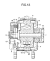
- Fig. 13 is a sectional view of the generator
- Fig. 14 is a perspective view of a rotor
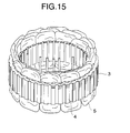
- Fig. 15 is a perspective view of a stator
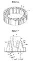
- Fig. 16 is a perspective view of a stator core
- Fig. 17 is a plane view showing a shape of magnetic poles of the rotor.
- numeral 1 is a front bracket
- numeral 2 is a rear bracket
- numeral 3 is a stator sandwiched between the front bracket 1 and the rear bracket 2.
- the stator 3 comprises a stator core 4 and a three-phase stator coil 5 inserted into a slot 4a of the stator core 4 as shown in Figs. 13, 15 and 16.
- numeral 6 is a rotor of claw pole type.
- the rotor 6 comprises a rotating shaft 7 whose both ends are supported by the front bracket 1 and the rear bracket 2, a first rotor core 8 and a second rotor core 9 mounted on this rotating shaft 7, a field coil 10 wound between both of the rotor cores 8 and 9, fans 11 and 12 provided in the back of both of the rotor cores 8 and 9, a pulley 13 provided outside the front bracket 1 side of the rotating shaft 7, and a slip ring 14 provided inside the rear bracket 2 side of the rotating shaft 7 for supplying a current to the field coil 10.
- Numeral 15 is a brush for supplying a current to the slip ring 14, and numeral 16 is a brush holder for holding this brush 15, and numeral 17 is a commutator for commutating alternating current output of the stator coil 5, and numeral 18 is a regulator for regulating a current of the field coil 10 to control an output voltage of the stator coil 5.
- Numerals 19 and 20 are magnetic poles axially extending to the inner diameter of the stator core 4 from the first rotor core 8 and the second rotor core 9 through a predetermined air gap.
- a plurality of the magnetic poles 19 extending from the first rotor core 8 and the magnetic poles 20 extending from the second rotor core 9 are respectively provided according to the number of poles of the generator and are arranged so as to have engagement alternately through predetermined gaps 21 and 22 between the magnetic poles and are magnetized in north poles and south poles alternately by excitation of the field coil 10.
- the magnetic poles 19 and 20 are formed into an isosceles trapezoid whose width is narrowed in the rotational direction toward the top end as shown in Fig.
- the centerlines indicated by the broken lines of the gaps 21 and 22 between the magnetic poles are set so as to incline in the range from about 60° to about 120° where an electrical angle between the adjacent magnetic poles 19 and 20 is set to 180° and, for example, the center of the magnetic pole 19 is set to 0° as shown in Fig. 17.
- chamfered parts 19a and 20a for smoothing a magnetic flux density of the air gap formed between the magnetic poles 19, 20 and the stator core 4 and suppressing electromagnetic noise are formed in the corner of the outer surface opposite to the stator core 4 of the magnetic poles 19 and 20 and both the end surfaces of the rotational direction.
- the magnetic poles 19 and 20 are excited alternately in the north pole and the south pole and the rotor 6 is driven by an internal combustion engine through the pulley 13 and thereby, the magnetic poles 19 and 20 give a rotating magnetic field to the stator core 4 and a three-phase alternating current voltage is generated in the stator coil 5 and this alternating current voltage is commutated by the commutator 17 for direct current and electric power is supplied to a load (not shown). Then, the regulator 18 holds an output voltage of the stator coil 5 to a constant value by controlling the passed current of the field coil 10.
- the rotating magnetic field given to the stator core 4 by the magnetic poles 19 and 20 is not a complete sine wave but a waveform including higher harmonics, and also an output current given to the load by power generation of the stator coil 5 is a current including higher harmonics.
- electromagnetic attraction force occurs between the magnetic poles 19, 20 and the stator core 4 due to interaction between the rotating magnetic field including higher harmonics and a magnetic field caused by an output current including higher harmonics, and this electromagnetic attraction force acts as applied vibration force, with the result that the stator core 4 and the magnetic poles 19, 20 vibrate to cause electromagnetic noise.
- a particular higher harmonic component among this electromagnetic noise interferes with quietness in the vehicle as abnormal sound, and various measures of noise have been taken.
- JP-A-54-134309 is also one of the measures of noise, and this technique notes that change in torque caused by periodic passage of the magnetic poles 19 and 20 arranged at regular pitches through the side of an inner diameter of teeth 4b arranged at regular pitches of the stator core 4 shown in Fig. 16 acts as applied vibration force to the stator core 4, and noise intends to be reduced by setting arrangement of the magnetic poles 19 and 20 at irregular pitches. According to this technique, the noise resulting from vibration the stator core 4 due to the change in torque is reduced, but the noise resulting from the electromagnetic attraction force between the stator core 4 and the magnetic poles 19, 20 cannot be reduced.
- the invention is implemented to solve such problems, and it is an object of the invention to obtain an alternating current generator for vehicle capable of effectively suppressing occurrence of abnormal sound without decrease in performance by reducing applied vibration force of higher harmonic components which can possibly become noise.
- An alternating current generator for vehicle comprises a stator core in which a three-phase stator coil is wound and inserted into slots, a first rotor core and a second rotor core which are provided in the side of an inner diameter of this stator core and rotate with a rotating shaft, a field coil for magnetizing these first and second rotor cores in different magnetic poles, and a plurality of magnetic poles which are provided so as to extend to an axial direction of the rotating shaft from the first and second rotor cores and are arranged so as to have engagement alternately through predetermined gaps between the magnetic poles and also are opposite to the surface of the inner diameter of the stator core through an air gap, and by forming these magnetic poles in a stepwise shape having a plurality of parts in the axial direction and setting the respective parts to different widths in a rotational direction, a pitch of the rotational direction between centerlines of the gaps between the adjacent magnetic poles is configured so as to change stepwise in the axial direction.
- the pitch of the rotational direction between the centerlines of the gaps between the adjacent magnetic poles is set to the range from 200° to 220° in a first part and the range from 140° to 160° in a second part using an electrical angle. Further, the pitch of the rotational direction between the centerlines of the gaps between the adjacent magnetic poles is set to the range from 220° to 230° in a first part, the range from 190° to 200° in a second part, the range from 160° to 170° in a third part and the range from 130° to 140° in a fourth part using an electrical angle.
- an alternating current generator for vehicle comprises a stator core in which a three-phase stator coil is wound and inserted into slots, a first rotor core and a second rotor core which are provided in the side of an inner diameter of this stator core and rotate with a rotating shaft, a field coil for magnetizing these first and second rotor cores in different magnetic poles, and a plurality of magnetic poles which are provided so as to extend to an axial direction of the rotating shaft from the first and second rotor cores and are arranged so as to have engagement alternately through predetermined gaps between the magnetic poles and also are opposite to the surface of the inner diameter of the stator core through an air gap, and these magnetic poles are formed in a substantially trapezoid shape of taper to the axial direction and also a part with a large angle of inclination to the axial direction is provided in the center of the axial direction and the axial length of this part is set to 30 % or shorter to the whole axial length of the magnetic poles.
- corners formed by the surface opposite to the inner diameter of the stator core of the magnetic poles and both sides of the rotational direction are chamfered. Furthermore, the number of slots per phase every pole provided in the stator core is one. Also, the number of slots per phase every pole provided in the stator core is two.
- Figs. 1 to 4 are configuration views and illustrations of an alternating current generator for vehicle of a first embodiment according to this invention
- Fig. 1 is a plane view showing a shape of magnetic poles
- Figs. 2 to 4 are illustrations of higher harmonics which generate a magnetic flux density and become a factor of noise.
- the whole configuration of the alternating current generator for vehicle and a configuration of a rotor are similar to the above-mentioned conventional example shown in Figs. 13 and 14, and only a configuration portion of the magnetic poles different from the conventional example will be described here.
- numeral 8 is a first rotor core provided in a rotor of the alternating current generator for vehicle
- numeral 9 is a second rotor core.
- the magnetic poles 23 and 24 which axially extend to the inner diameter of a stator core 4 from the first rotor core 8 and the second rotor core 9 through a predetermined air gap and are arranged so as to have engagement alternately.
- the magnetic poles 23 and 24 comprise first parts 23a and 24a, and second parts 23b and 24b with a different width in the rotational direction, respectively, and they are stepwise formed in the axial direction, and also the first parts 23a and 24a are set to an electrical angle of 210° at a pitch between the centerlines shown by broken lines of gaps 25 and 26 between the magnetic poles, and the second parts 23b and 24b are also set to an electrical angle of 150° similarly.
- the applied vibration force of the order of six times the number of magnetic poles mainly occurs from a composite value of interaction between a lip-order spatial higher harmonic of the rotor side and a lip-order spatial higher harmonic of the stator coil side with interaction between a 13p-order spatial higher harmonic of the rotor side and a 13p-order spatial higher harmonic of the stator coil side.
- it is effective to reduce the 5p-order and 7p-order spatial higher harmonics of the rotor side in the generator where the number of slots per phase every pole is one and the lip-order and 13p-order spatial higher harmonics in the generator where the number of slots per phase every pole is two.
- Fig. 17 employed in explanation of the conventional example.
- a widthwise dimension of two-dimensional cross section of the magnetic poles sectioned in a plane vertical to the rotating shaft 7, namely a line pitch between centerlines of the gaps between the adjacent magnetic poles straightly changes depending on an axial position, so that the amplitude and phase of the spatial higher harmonics continuously change depending on the axial position.
- each order component of the spatial higher harmonics exists with the order components continuously changing depending on the position of an arrow z-direction of Fig. 17 and the z position in which the order component of the spatial higher harmonics becoming a factor of the electromagnetic noise is increased exists, with the result that the electromagnetic applied vibration force of this order component brings about resonance of the stator core or the magnetic poles to increase the electromagnetic noise.
- Fig. 2 The amplitude and phase of the 5p-order higher harmonic among these order components of the higher harmonics to a pitch of the magnetic poles are shown in Fig. 2.
- the axis of abscissa of Fig. 2 indicates the pole pitch of the magnetic poles by an electrical angle, and the center of one magnetic pole is 0° and the center of the adjacent magnetic pole is ⁇ , namely 180° as shown in Fig. 17. Then, the centerline of the gaps between the magnetic poles exists in the range from 57° to 123° as shown by thin lines in Fig. 2, and also the range from 180° to 360° is symmetric with respect to a line of 180° .
- the 5p-order higher harmonic of such a generator is distributed between the pitch of the magnetic poles as shown in Fig. 2, and becomes the minimum value at positions of ⁇ 90° /5 around 90°, namely 72° and 108°, and also the phase of the higher harmonic reverses by 180° every 36° (180° /5) as shown by a broken line.
- Fig. 3 shows the 7p-order higher harmonic similarly and indicates that the phase reverses by 180° every 180° /7.
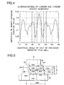
- the applied vibration force of the three times order appears remarkably and is generated by composition of the 5p-order spatial higher harmonic with the 7p-order spatial higher harmonic, and this is shown in Fig. 4.
- Fig. 4 is the composition of the 5p-order spatial higher harmonic of Fig. 2 with the 7p-order spatial higher harmonic of Fig. 3 assuming that the peak value is 7:5, namely the peak value of n-order higher harmonics is 1/n). As is evident from Fig.
- the small amplitude portions of the composite wave exist in the range from 70° to 80° and the range from 100° to 110° using an electrical angle, and it is indicated that if the interface between the magnetic poles, namely the centerline of the gap between the magnetic poles exists in positions of these small amplitude portions, the applied vibration force of the three times order is reduced and the electromagnetic applied vibration force decreases in the three-phase alternating current generator where the number of slots of the stator core per phase every pole is one and thereby the electromagnetic noise is reduced. Then, when the positions are replaced with a pitch between the centerlines of the gaps between the magnetic poles, the pitch corresponds to the range from 140° to 160° and the range from 200° to 220° .
- the pitch between the centerlines of the gaps 25 and 26 between the magnetic poles is set to an electrical angle of 210° in the first parts 23a and 24a and is set to an electrical angle of 150° in the second parts 23b and 24b and is selected so that the amplitude of the electromagnetic applied vibration force of the three times order becomes small, with the result that the electromagnetic applied vibration force of the three times order to the magnetic poles 23 and 24 is considerably reduced and a configuration of the rotor capable of remarkably decreasing the electromagnetic noise by use in the generator where the number of slots of the stator core per phase every pole is one can be obtained.
- Fig. 5 is a plane view showing a shape of magnetic poles of an alternating current generator for vehicle of a second embodiment according to the invention. This embodiment is implemented to reduce the electromagnetic applied vibration force of the three times order in a three-phase alternating current generator where the number of slots of the stator core per phase every pole is one similar to the first embodiment.
- magnetic poles 23 and 24 which axially extend from a first rotor core 8 and a second rotor core 9 comprise first parts 23a and 24a, and second parts 23b and 24b with a different width in the rotational direction, respectively.
- the first parts 23a and 24a are slantingly formed so that a pitch between the centerlines of gaps 25 and 26 between the magnetic poles is set to an electrical angle of 220° to 200°, and the second parts 23b and 24b are slantingly formed so that the line pitch is set to an electrical angle of 140° to 160°.
- the pitch between the centerlines of the gaps between the magnetic poles is selected so that the amplitude of the electromagnetic applied vibration force of the three times order becomes small and the electromagnetic noise can be reduced similar to the first embodiment.
- Figs. 6 to 9 are configuration views and illustrations of an alternating current generator for vehicle of a third embodiment according to the invention
- Fig. 6 is a plane view showing a shape of magnetic poles
- Figs. 7 to 9 are illustrations of higher harmonics which generate a magnetic pole and become a factor of noise.
- This embodiment adapts to a three-phase alternating current generator where the number of slots of the stator core per phase every pole is two. As described in the first embodiment, in the case where the number of slots of the stator core is two, the applied vibration force of the order of six times the number of magnetic poles appears remarkably and is generated by composition of a 11p-order spatial higher harmonic with a 13p-order spatial higher harmonic.
- Fig. 7 shows the amplitude and phase of the 11p-order higher harmonic to a pitch of the magnetic poles
- Fig. 8 shows the amplitude and phase of the 13p-order higher harmonic to a pitch of the magnetic poles
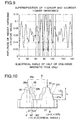
- Fig. 9 is the composition of the 11p-order spatial higher harmonic of Fig. 7 with the 13p-order spatial higher harmonic of Fig. 8 assuming that the peak value is 13:11.
- positions with the small amplitude of the applied vibration force of the six times order exist in the range from 65° to 70°, the range from 80° to 85°, the range from 95° to 100°, and the range from 110° to 115°. If the interface between the magnetic poles, namely the centerline of the gap between the magnetic poles exists in these positions, the applied vibration force of the six times order is reduced.
- the pitch exists in the range from 130° to 140°, the range from 160° to 170°, the range from 190° to 200°, and the range from 220° to 230°, and the electromagnetic applied vibration force decreases in these ranges.
- a magnetic pole 23 extending from a first rotor core 8 and a magnetic pole 24 extending from a second rotor core 9 comprise four parts 23a and 24a, 23b and 24b, 23c and 24c, 23d and 24d with a different width in the rotational direction, respectively.
- Line pitches between the centerlines of gaps 25 and 26 between the adjacent magnetic poles shown by dottod lines are set to electrical angles of 225°, 195°, 165° and 135°, and the line pitches between the centerlines of the gaps between the magnetic poles are selected so that the amplitude of the electromagnetic applied vibration force of the six times order becomes small.
- the electromagnetic applied vibration force of the six times order to the magnetic poles 23 and 24 is considerably reduced and a configuration of the rotor capable of remarkably decreasing the electromagnetic noise by use in the generator where the number of slots of the stator core per phase every pole is two can be obtained.
- Fig. 10 is a plane view showing a shape of magnetic poles of an alternating current generator for vehicle of a fourth embodiment according to the invention
- Fig. 11 is an illustration showing effect.
- a magnetic pole 27 extending from a rotor core 8 and a magnetic pole 28 extending from a rotor core 9 are formed in a substantially trapezoid shape, and first trapezoid parts 27a and 28a with a wide width in the rotational direction and second trapezoid parts 27b and 28b with a narrow width in the rotational direction are provided, and parts 27c and 28c with a large angle of inclination in which a width of the magnetic pole changes sharply in the range of an axial length of L3 are provided in the center of the axial length of the magnetic poles 27 and 28 between the first trapezoid parts 27a and 28a and the second trapezoid parts 27b and 28b.
- the axial length L3 of the parts 27c and 28c with a large angle of inclination is
- the electromagnetic noise intends to be reduced by setting the magnetic poles 23 and 24 to a width of the rotational direction so that order components of the electromagnetic applied vibration force become small, but even if a large portion of the electromagnetic applied vibration force exists, the electromagnetic noise can be reduced by decreasing the value obtained by axially integrating this electromagnetic applied vibration force, and the integral value of the axial electromagnetic applied vibration force can be decreased by providing a portion in which the width of the rotational direction of the magnetic poles sharply changes, namely the pitch between the centerlines of the gaps between the magnetic poles sharply changes in the center of the longitudinal direction.
- Fig. 11 shows a relationship of the axial integral value of the electromagnetic applied vibration force to a sharp change position of the pitch between the centerlines of the gaps between the magnetic poles, and as is evident from Fig. 11, the integral value of each order component of higher harmonics becomes small in the range from 80° to 90° using an electrical angle.
- Fig. 11 becomes symmetric with respect to a line to the position of 90° and the range from 80° to 100° becomes a small range of the integral value of higher harmonics in the shape of the magnetic poles of Fig. 10.
- the ratio of both the ranges is (100-80)/(123-57) ⁇ 0.3. Also, since the position of 90° is the center between the magnetic poles, by setting the length L3 of inclination with sharp change to 30 % or shorter to the axial length L of the magnetic poles 27 and 28 and setting the position to the center of the axial length, a sharp change portion of an angle of inclination can be set to the position in which the integral value of each order component of higher harmonics becomes small and thus reduction in electromagnetic noise can be achieved.
- Fig. 12 is a plane view showing a shape of magnetic poles of an alternating current generator for vehicle of a fifth embodiment according to the invention.
- this embodiment is configured so that chamfered parts 23e and 24e for smoothing a magnetic flux density of the air gap formed between a stator core and corners to suppress electromagnetic noise are provided in the corners formed by the outer surface of each the magnetic pole opposite to the stator core and both sides of the rotational direction, and Fig. 12 shows the case of the first embodiment as a typical example. By such a configuration, the electromagnetic noise described above can be more effectively reduced.
- the magnetic poles 23 and 24 or the magnetic poles 27 and 28 mentioned above have been described with reference to the case of a generator form in which the field coil rotates with the rotor core, but they can be similarly applied even to the case of a generator form in which the field coil fixed separately from the rotor core is provided and only the rotor core rotates, a so-called inductor rotation type generator.
- a width of the rotational direction of magnetic poles namely a pitch between the centerlines of gaps between the magnetic poles is not changed continuously and the width is stepwise changed so as to avoid order components of higher harmonics of electromagnetic applied vibration force, or a sharp change position of the width of the rotational direction is set to a part in which the axial integral value of the electromagnetic applied vibration force becomes minimum, so that electromagnetic noise resulting from the electromagnetic applied vibration force can be remarkably reduced and the alternating current generator for vehicle with excellent quietness can be obtained.
Landscapes
- Engineering & Computer Science (AREA)
- Power Engineering (AREA)
- Synchronous Machinery (AREA)
- Iron Core Of Rotating Electric Machines (AREA)
Abstract
Description
Claims (7)
- An alternating current generator for vehicle, comprising:a stator core in which a three-phase stator coil is wound and inserted into slots,a first rotor core and a second rotor core which are provided in the side of an inner diameter of said stator core and rotate with a rotating shaft,a field coil for magnetizing said first and second rotor cores in different magnetic poles, anda plurality of magnetic poles which are provided so as to extend to an axial direction of said rotating shaft from said first and second rotor cores and are arranged so as to have engagement alternately through predetermined gaps between said magnetic poles and are opposite to the surface of the inner diameter of said stator core through an air gap, whereinsaid magnetic poles have a plurality of parts in the axial direction and are stepwise formed and the respective parts are set to different widths in a rotational direction, so that a pitch of the rotational direction between centerlines of the gaps between said adjacent magnetic poles is configured so as to change stepwise in the axial direction.
- The alternating current generator for vehicle as defined in claim 1, wherein
the pitch of the rotational direction between the centerlines of the gaps between said adjacent magnetic poles is set to the range from 200° to 220° in a first part and the range from 140° to 160° in a second part using an electrical angle. - The alternating current generator for vehicle as defined in claim 1, wherein
the pitch of the rotational direction between the centerlines of the gaps between said adjacent magnetic poles is set to the range from 220° to 230° in a first part, the range from 190° to 200° in a second part, the range from 160° to 170° in a third part, and the range from 130° to 140° in a fourth part using an electrical angle. - An alternating current generator for vehicle, comprising:a stator core in which a three-phase stator coil is wound and inserted into slots,a first rotor core and a second rotor core which are provided in the side of an inner diameter of said stator core and rotate with a rotating shaft,a field coil for magnetizing said first and second rotor cores in different magnetic poles, anda plurality of magnetic poles which are provided so as to extend to an axial direction of the rotating shaft from said first and second rotor cores and are arranged so as to have engagement alternately through predetermined gaps between said magnetic poles and are opposite to the surface of the inner diameter of said stator core through an air gap, whereinsaid magnetic poles are formed in a substantially trapezoid shape of taper to the axial direction, and a part with a large angle of inclination to the axial direction is provided in the center of the axial direction, andthe axial length of said part is set to 30 % or shorter to the whole axial length of said magnetic poles.
- The alternating current generator for vehicle as defined in any one of claims 1 to 4, wherein
corners formed by the surface opposite to the inner diameter of said stator core of said magnetic poles and both sides of the rotational direction are chamfered. - The alternating current generator for vehicle as defined in any one of claims 1, 2, 4 or 5, wherein
the number of slots per phase every pole provided in said stator core is one. - The alternating current generator for vehicle as defined in any one of claims 1, 3, 4 or 5, wherein
the number of slots per phase every pole provided in said stator core is two.
Applications Claiming Priority (2)
| Application Number | Priority Date | Filing Date | Title |
|---|---|---|---|
| JP2000029356A JP4049963B2 (en) | 2000-02-07 | 2000-02-07 | AC generator for vehicles |
| JP2000029356 | 2000-02-07 |
Publications (3)
| Publication Number | Publication Date |
|---|---|
| EP1122858A2 true EP1122858A2 (en) | 2001-08-08 |
| EP1122858A3 EP1122858A3 (en) | 2004-01-14 |
| EP1122858B1 EP1122858B1 (en) | 2005-10-26 |
Family
ID=18554630
Family Applications (1)
| Application Number | Title | Priority Date | Filing Date |
|---|---|---|---|
| EP00116232A Expired - Lifetime EP1122858B1 (en) | 2000-02-07 | 2000-08-07 | Alternating current generator for vehicle |
Country Status (5)
| Country | Link |
|---|---|
| US (2) | US6404096B1 (en) |
| EP (1) | EP1122858B1 (en) |
| JP (1) | JP4049963B2 (en) |
| KR (1) | KR100399741B1 (en) |
| DE (1) | DE60023437T2 (en) |
Cited By (2)
| Publication number | Priority date | Publication date | Assignee | Title |
|---|---|---|---|---|
| EP1276203A1 (en) * | 2001-07-06 | 2003-01-15 | Delphi Technologies, Inc. | Alternating current generator |
| FR2999822A1 (en) * | 2012-12-19 | 2014-06-20 | Valeo Equip Electr Moteur | SECTION-REDUCING CLUTCH ROTOR AND ALTERNATOR, IN PARTICULAR OF A MOTOR VEHICLE COMPRISING SUCH A ROTOR |
Families Citing this family (11)
| Publication number | Priority date | Publication date | Assignee | Title |
|---|---|---|---|---|
| JP4020758B2 (en) | 2002-11-13 | 2007-12-12 | 三菱電機株式会社 | Rotating electric machine for vehicles |
| US7105960B2 (en) * | 2004-02-24 | 2006-09-12 | Denso Corporation | Generator mountable to vehicle |
| JP4525118B2 (en) * | 2004-03-12 | 2010-08-18 | 日産自動車株式会社 | Electric motor |
| KR101082929B1 (en) | 2005-04-28 | 2011-11-11 | 가부시키가이샤 덴소 | Ac motor |
| JP4887128B2 (en) * | 2006-12-07 | 2012-02-29 | 日立オートモティブシステムズ株式会社 | Rotating electric machine |
| JP4640422B2 (en) * | 2008-02-29 | 2011-03-02 | 株式会社デンソー | Landel rotor type motor |
| JP5115389B2 (en) * | 2008-08-04 | 2013-01-09 | 株式会社デンソー | Field coil type rotating electrical machine |
| US9887608B2 (en) | 2013-01-24 | 2018-02-06 | Asmo Co., Ltd. | Rotor, stator and motor |
| US9577501B2 (en) * | 2013-04-05 | 2017-02-21 | Remy Technologies, Llc | Claw pole rotor with cavity for minimizing flux leakage |
| FR3024607A1 (en) * | 2014-07-31 | 2016-02-05 | Francecol Technology | COMPOUND HOMOPOLAR MACHINE |
| DE102017103027A1 (en) * | 2017-02-15 | 2018-08-16 | Rausch & Pausch Gmbh | LINEAR |
Family Cites Families (13)
| Publication number | Priority date | Publication date | Assignee | Title |
|---|---|---|---|---|
| US3226581A (en) * | 1961-06-29 | 1965-12-28 | Motorola Inc | Generating system |
| US3571639A (en) * | 1968-03-22 | 1971-03-23 | Trw Inc | Dual-section brushless alternator |
| FR2082430A5 (en) * | 1970-03-16 | 1971-12-10 | Ducellier & Cie | |
| JPS5420310A (en) * | 1977-07-15 | 1979-02-15 | Nippon Soken | Ac generator for vehicle |
| JPS54134309A (en) | 1978-04-10 | 1979-10-18 | Nippon Soken | Ac power generator for vehicles |
| US4780637A (en) * | 1985-12-20 | 1988-10-25 | Eaton Corporation | Brushless eddy current coupling - stationary field |
| DE3704156A1 (en) * | 1987-02-11 | 1988-08-25 | Bosch Gmbh Robert | AC GENERATOR WITH CLAW POLO ROTOR |
| JP2938981B2 (en) * | 1990-12-28 | 1999-08-25 | 澤藤電機株式会社 | Rotor for AC rotary electric machine |
| FR2676873B1 (en) * | 1991-05-21 | 1993-08-06 | Valeo Equipements Electr Mo | THREE - PHASE ALTERNATOR FOR MOTOR VEHICLES. |
| JPH0556615A (en) * | 1991-08-22 | 1993-03-05 | Nippondenso Co Ltd | Ac generator |
| JP3265967B2 (en) * | 1996-02-09 | 2002-03-18 | 株式会社デンソー | Alternator |
| JP3929615B2 (en) * | 1998-09-01 | 2007-06-13 | 三菱電機株式会社 | AC generator for vehicles |
| US6310416B1 (en) * | 2000-02-11 | 2001-10-30 | Huang-Tung Chang | Resisting and pulling mechanism |
-
2000
- 2000-02-07 JP JP2000029356A patent/JP4049963B2/en not_active Expired - Fee Related
- 2000-08-07 DE DE60023437T patent/DE60023437T2/en not_active Expired - Lifetime
- 2000-08-07 EP EP00116232A patent/EP1122858B1/en not_active Expired - Lifetime
- 2000-08-08 US US09/635,005 patent/US6404096B1/en not_active Expired - Lifetime
- 2000-10-04 KR KR10-2000-0058169A patent/KR100399741B1/en not_active Expired - Fee Related
-
2002
- 2002-03-22 US US10/102,854 patent/US6531803B2/en not_active Expired - Lifetime
Cited By (5)
| Publication number | Priority date | Publication date | Assignee | Title |
|---|---|---|---|---|
| EP1276203A1 (en) * | 2001-07-06 | 2003-01-15 | Delphi Technologies, Inc. | Alternating current generator |
| US6703758B2 (en) | 2001-07-06 | 2004-03-09 | Delphi Technologies, Inc. | Rotor for an AC generator |
| FR2999822A1 (en) * | 2012-12-19 | 2014-06-20 | Valeo Equip Electr Moteur | SECTION-REDUCING CLUTCH ROTOR AND ALTERNATOR, IN PARTICULAR OF A MOTOR VEHICLE COMPRISING SUCH A ROTOR |
| WO2014096642A3 (en) * | 2012-12-19 | 2015-06-04 | Valeo Equipements Electriques Moteur | Claw rotor comprising claws having a reduction in cross-section and alternator, for a motor vehicle comprising such a rotor |
| US10193404B2 (en) | 2012-12-19 | 2019-01-29 | Valeo Equipements Electriques Moteur | Claw rotor with reduced cross-section, and alternator comprising rotor of this type |
Also Published As
| Publication number | Publication date |
|---|---|
| US20020096964A1 (en) | 2002-07-25 |
| KR20010077890A (en) | 2001-08-20 |
| EP1122858B1 (en) | 2005-10-26 |
| KR100399741B1 (en) | 2003-09-29 |
| DE60023437T2 (en) | 2006-07-13 |
| EP1122858A3 (en) | 2004-01-14 |
| JP4049963B2 (en) | 2008-02-20 |
| US6531803B2 (en) | 2003-03-11 |
| JP2001218395A (en) | 2001-08-10 |
| US6404096B1 (en) | 2002-06-11 |
| DE60023437D1 (en) | 2005-12-01 |
Similar Documents
| Publication | Publication Date | Title |
|---|---|---|
| US7034424B2 (en) | Permanent magnetic rotating machine | |
| US7183684B2 (en) | Permanent magnet rotary motor | |
| CN1081844C (en) | Permanent magnet inserted type rotor structure | |
| CN1157675A (en) | Commutatorless polyphase AC electric machine | |
| EP1122858B1 (en) | Alternating current generator for vehicle | |
| US20070252467A1 (en) | Interior Magnet Machine With Non-Perpendicular Slots | |
| JP2002262490A (en) | Motor or generator | |
| JP2002354720A (en) | AC generator for vehicles | |
| CN103959608A (en) | Rotor for a rotary electric machine and rotary electric machine comprising such a rotor | |
| JP2006271187A (en) | Rotating electric machine | |
| KR100621954B1 (en) | Automotive Alternator | |
| JPH10210721A (en) | Reluctance motor | |
| US6847150B2 (en) | Rotating electrical machine for vehicle | |
| CN110620447B (en) | Permanent magnet motor and compressor | |
| JP3214508B2 (en) | AC generator for vehicles | |
| JP4894273B2 (en) | Rotating electric machine | |
| US20050116581A1 (en) | Rotor for dynamo-electric machine | |
| CN114189067B (en) | Stator structure, motor and electrical equipment | |
| CN112072815A (en) | High-speed inner rotor motor for electric motorcycle | |
| CN114640202A (en) | Rotor assembly and axial flux permanent magnet motor | |
| JP5190131B2 (en) | Induction motor | |
| CN112368909B (en) | Rotary electric machine | |
| CN120582368A (en) | Stator core assembly, stator assembly, motor, suspension system and vehicle | |
| CN120474294A (en) | Motors, motor servo systems, suspension systems and automobiles | |
| JP2008067483A (en) | Positive salient-pole motor |
Legal Events
| Date | Code | Title | Description |
|---|---|---|---|
| PUAI | Public reference made under article 153(3) epc to a published international application that has entered the european phase |
Free format text: ORIGINAL CODE: 0009012 |
|
| AK | Designated contracting states |
Kind code of ref document: A2 Designated state(s): AT BE CH CY DE DK ES FI FR GB GR IE IT LI LU MC NL PT SE |
|
| AX | Request for extension of the european patent |
Free format text: AL;LT;LV;MK;RO;SI |
|
| PUAL | Search report despatched |
Free format text: ORIGINAL CODE: 0009013 |
|
| AK | Designated contracting states |
Kind code of ref document: A3 Designated state(s): AT BE CH CY DE DK ES FI FR GB GR IE IT LI LU MC NL PT SE |
|
| AX | Request for extension of the european patent |
Extension state: AL LT LV MK RO SI |
|
| 17P | Request for examination filed |
Effective date: 20040310 |
|
| 17Q | First examination report despatched |
Effective date: 20040419 |
|
| AKX | Designation fees paid |
Designated state(s): DE FR GB |
|
| GRAP | Despatch of communication of intention to grant a patent |
Free format text: ORIGINAL CODE: EPIDOSNIGR1 |
|
| GRAS | Grant fee paid |
Free format text: ORIGINAL CODE: EPIDOSNIGR3 |
|
| GRAA | (expected) grant |
Free format text: ORIGINAL CODE: 0009210 |
|
| AK | Designated contracting states |
Kind code of ref document: B1 Designated state(s): DE FR GB |
|
| REG | Reference to a national code |
Ref country code: GB Ref legal event code: FG4D |
|
| REF | Corresponds to: |
Ref document number: 60023437 Country of ref document: DE Date of ref document: 20051201 Kind code of ref document: P |
|
| RAP2 | Party data changed (patent owner data changed or rights of a patent transferred) |
Owner name: MITSUBISHI DENKI KABUSHIKI KAISHA |
|
| ET | Fr: translation filed | ||
| REG | Reference to a national code |
Ref country code: GB Ref legal event code: 727 |
|
| PLBE | No opposition filed within time limit |
Free format text: ORIGINAL CODE: 0009261 |
|
| STAA | Information on the status of an ep patent application or granted ep patent |
Free format text: STATUS: NO OPPOSITION FILED WITHIN TIME LIMIT |
|
| REG | Reference to a national code |
Ref country code: GB Ref legal event code: 727A |
|
| 26N | No opposition filed |
Effective date: 20060727 |
|
| REG | Reference to a national code |
Ref country code: GB Ref legal event code: 727B |
|
| PGFP | Annual fee paid to national office [announced via postgrant information from national office to epo] |
Ref country code: DE Payment date: 20100812 Year of fee payment: 11 Ref country code: FR Payment date: 20100824 Year of fee payment: 11 |
|
| PGFP | Annual fee paid to national office [announced via postgrant information from national office to epo] |
Ref country code: GB Payment date: 20100811 Year of fee payment: 11 |
|
| GBPC | Gb: european patent ceased through non-payment of renewal fee |
Effective date: 20110807 |
|
| REG | Reference to a national code |
Ref country code: FR Ref legal event code: ST Effective date: 20120430 |
|
| REG | Reference to a national code |
Ref country code: DE Ref legal event code: R119 Ref document number: 60023437 Country of ref document: DE Effective date: 20120301 |
|
| PG25 | Lapsed in a contracting state [announced via postgrant information from national office to epo] |
Ref country code: FR Free format text: LAPSE BECAUSE OF NON-PAYMENT OF DUE FEES Effective date: 20110831 Ref country code: GB Free format text: LAPSE BECAUSE OF NON-PAYMENT OF DUE FEES Effective date: 20110807 |
|
| PG25 | Lapsed in a contracting state [announced via postgrant information from national office to epo] |
Ref country code: DE Free format text: LAPSE BECAUSE OF NON-PAYMENT OF DUE FEES Effective date: 20120301 |