EP1122723A1 - Optical recording medium, optical recording method, optical reproducing method, optical recording device, optical reproducing device, and optical recording/reproducing device - Google Patents
Optical recording medium, optical recording method, optical reproducing method, optical recording device, optical reproducing device, and optical recording/reproducing device Download PDFInfo
- Publication number
- EP1122723A1 EP1122723A1 EP00946419A EP00946419A EP1122723A1 EP 1122723 A1 EP1122723 A1 EP 1122723A1 EP 00946419 A EP00946419 A EP 00946419A EP 00946419 A EP00946419 A EP 00946419A EP 1122723 A1 EP1122723 A1 EP 1122723A1
- Authority
- EP
- European Patent Office
- Prior art keywords
- recording
- optical
- reflective film
- reflectance
- information
- Prior art date
- Legal status (The legal status is an assumption and is not a legal conclusion. Google has not performed a legal analysis and makes no representation as to the accuracy of the status listed.)
- Granted
Links
Images


Classifications
-
- G—PHYSICS
- G11—INFORMATION STORAGE
- G11B—INFORMATION STORAGE BASED ON RELATIVE MOVEMENT BETWEEN RECORD CARRIER AND TRANSDUCER
- G11B23/00—Record carriers not specific to the method of recording or reproducing; Accessories, e.g. containers, specially adapted for co-operation with the recording or reproducing apparatus ; Intermediate mediums; Apparatus or processes specially adapted for their manufacture
- G11B23/28—Indicating or preventing prior or unauthorised use, e.g. cassettes with sealing or locking means, write-protect devices for discs
- G11B23/281—Indicating or preventing prior or unauthorised use, e.g. cassettes with sealing or locking means, write-protect devices for discs by changing the physical properties of the record carrier
-
- G—PHYSICS
- G11—INFORMATION STORAGE
- G11B—INFORMATION STORAGE BASED ON RELATIVE MOVEMENT BETWEEN RECORD CARRIER AND TRANSDUCER
- G11B7/00—Recording or reproducing by optical means, e.g. recording using a thermal beam of optical radiation by modifying optical properties or the physical structure, reproducing using an optical beam at lower power by sensing optical properties; Record carriers therefor
- G11B7/24—Record carriers characterised by shape, structure or physical properties, or by the selection of the material
- G11B7/2403—Layers; Shape, structure or physical properties thereof
- G11B7/24062—Reflective layers
-
- G—PHYSICS
- G11—INFORMATION STORAGE
- G11B—INFORMATION STORAGE BASED ON RELATIVE MOVEMENT BETWEEN RECORD CARRIER AND TRANSDUCER
- G11B20/00—Signal processing not specific to the method of recording or reproducing; Circuits therefor
- G11B20/00086—Circuits for prevention of unauthorised reproduction or copying, e.g. piracy
-
- G—PHYSICS
- G11—INFORMATION STORAGE
- G11B—INFORMATION STORAGE BASED ON RELATIVE MOVEMENT BETWEEN RECORD CARRIER AND TRANSDUCER
- G11B20/00—Signal processing not specific to the method of recording or reproducing; Circuits therefor
- G11B20/00086—Circuits for prevention of unauthorised reproduction or copying, e.g. piracy
- G11B20/00094—Circuits for prevention of unauthorised reproduction or copying, e.g. piracy involving measures which result in a restriction to authorised record carriers
- G11B20/00123—Circuits for prevention of unauthorised reproduction or copying, e.g. piracy involving measures which result in a restriction to authorised record carriers the record carrier being identified by recognising some of its unique characteristics, e.g. a unique defect pattern serving as a physical signature of the record carrier
-
- G—PHYSICS
- G11—INFORMATION STORAGE
- G11B—INFORMATION STORAGE BASED ON RELATIVE MOVEMENT BETWEEN RECORD CARRIER AND TRANSDUCER
- G11B20/00—Signal processing not specific to the method of recording or reproducing; Circuits therefor
- G11B20/00086—Circuits for prevention of unauthorised reproduction or copying, e.g. piracy
- G11B20/00166—Circuits for prevention of unauthorised reproduction or copying, e.g. piracy involving measures which result in a restriction to authorised contents recorded on or reproduced from a record carrier, e.g. music or software
- G11B20/00173—Circuits for prevention of unauthorised reproduction or copying, e.g. piracy involving measures which result in a restriction to authorised contents recorded on or reproduced from a record carrier, e.g. music or software wherein the origin of the content is checked, e.g. determining whether the content has originally been retrieved from a legal disc copy or another trusted source
-
- G—PHYSICS
- G11—INFORMATION STORAGE
- G11B—INFORMATION STORAGE BASED ON RELATIVE MOVEMENT BETWEEN RECORD CARRIER AND TRANSDUCER
- G11B20/00—Signal processing not specific to the method of recording or reproducing; Circuits therefor
- G11B20/00086—Circuits for prevention of unauthorised reproduction or copying, e.g. piracy
- G11B20/0021—Circuits for prevention of unauthorised reproduction or copying, e.g. piracy involving encryption or decryption of contents recorded on or reproduced from a record carrier
-
- G—PHYSICS
- G11—INFORMATION STORAGE
- G11B—INFORMATION STORAGE BASED ON RELATIVE MOVEMENT BETWEEN RECORD CARRIER AND TRANSDUCER
- G11B20/00—Signal processing not specific to the method of recording or reproducing; Circuits therefor
- G11B20/00086—Circuits for prevention of unauthorised reproduction or copying, e.g. piracy
- G11B20/00572—Circuits for prevention of unauthorised reproduction or copying, e.g. piracy involving measures which change the format of the recording medium
- G11B20/00586—Circuits for prevention of unauthorised reproduction or copying, e.g. piracy involving measures which change the format of the recording medium said format change concerning the physical format of the recording medium
- G11B20/00594—Circuits for prevention of unauthorised reproduction or copying, e.g. piracy involving measures which change the format of the recording medium said format change concerning the physical format of the recording medium wherein the shape of recording marks is altered, e.g. the depth, width, or length of pits
-
- G—PHYSICS
- G11—INFORMATION STORAGE
- G11B—INFORMATION STORAGE BASED ON RELATIVE MOVEMENT BETWEEN RECORD CARRIER AND TRANSDUCER
- G11B20/00—Signal processing not specific to the method of recording or reproducing; Circuits therefor
- G11B20/00086—Circuits for prevention of unauthorised reproduction or copying, e.g. piracy
- G11B20/00572—Circuits for prevention of unauthorised reproduction or copying, e.g. piracy involving measures which change the format of the recording medium
- G11B20/00586—Circuits for prevention of unauthorised reproduction or copying, e.g. piracy involving measures which change the format of the recording medium said format change concerning the physical format of the recording medium
- G11B20/00601—Circuits for prevention of unauthorised reproduction or copying, e.g. piracy involving measures which change the format of the recording medium said format change concerning the physical format of the recording medium wherein properties of tracks are altered, e.g., by changing the wobble pattern or the track pitch, or by adding interruptions or eccentricity
-
- G—PHYSICS
- G11—INFORMATION STORAGE
- G11B—INFORMATION STORAGE BASED ON RELATIVE MOVEMENT BETWEEN RECORD CARRIER AND TRANSDUCER
- G11B20/00—Signal processing not specific to the method of recording or reproducing; Circuits therefor
- G11B20/00086—Circuits for prevention of unauthorised reproduction or copying, e.g. piracy
- G11B20/00884—Circuits for prevention of unauthorised reproduction or copying, e.g. piracy involving a watermark, i.e. a barely perceptible transformation of the original data which can nevertheless be recognised by an algorithm
-
- G—PHYSICS
- G11—INFORMATION STORAGE
- G11B—INFORMATION STORAGE BASED ON RELATIVE MOVEMENT BETWEEN RECORD CARRIER AND TRANSDUCER
- G11B7/00—Recording or reproducing by optical means, e.g. recording using a thermal beam of optical radiation by modifying optical properties or the physical structure, reproducing using an optical beam at lower power by sensing optical properties; Record carriers therefor
- G11B7/004—Recording, reproducing or erasing methods; Read, write or erase circuits therefor
- G11B7/0045—Recording
-
- G—PHYSICS
- G11—INFORMATION STORAGE
- G11B—INFORMATION STORAGE BASED ON RELATIVE MOVEMENT BETWEEN RECORD CARRIER AND TRANSDUCER
- G11B7/00—Recording or reproducing by optical means, e.g. recording using a thermal beam of optical radiation by modifying optical properties or the physical structure, reproducing using an optical beam at lower power by sensing optical properties; Record carriers therefor
- G11B7/004—Recording, reproducing or erasing methods; Read, write or erase circuits therefor
- G11B7/0045—Recording
- G11B7/00455—Recording involving reflectivity, absorption or colour changes
-
- G—PHYSICS
- G11—INFORMATION STORAGE
- G11B—INFORMATION STORAGE BASED ON RELATIVE MOVEMENT BETWEEN RECORD CARRIER AND TRANSDUCER
- G11B7/00—Recording or reproducing by optical means, e.g. recording using a thermal beam of optical radiation by modifying optical properties or the physical structure, reproducing using an optical beam at lower power by sensing optical properties; Record carriers therefor
- G11B7/004—Recording, reproducing or erasing methods; Read, write or erase circuits therefor
- G11B7/005—Reproducing
-
- G—PHYSICS
- G11—INFORMATION STORAGE
- G11B—INFORMATION STORAGE BASED ON RELATIVE MOVEMENT BETWEEN RECORD CARRIER AND TRANSDUCER
- G11B7/00—Recording or reproducing by optical means, e.g. recording using a thermal beam of optical radiation by modifying optical properties or the physical structure, reproducing using an optical beam at lower power by sensing optical properties; Record carriers therefor
- G11B7/007—Arrangement of the information on the record carrier, e.g. form of tracks, actual track shape, e.g. wobbled, or cross-section, e.g. v-shaped; Sequential information structures, e.g. sectoring or header formats within a track
-
- G—PHYSICS
- G11—INFORMATION STORAGE
- G11B—INFORMATION STORAGE BASED ON RELATIVE MOVEMENT BETWEEN RECORD CARRIER AND TRANSDUCER
- G11B7/00—Recording or reproducing by optical means, e.g. recording using a thermal beam of optical radiation by modifying optical properties or the physical structure, reproducing using an optical beam at lower power by sensing optical properties; Record carriers therefor
- G11B7/24—Record carriers characterised by shape, structure or physical properties, or by the selection of the material
-
- G—PHYSICS
- G11—INFORMATION STORAGE
- G11B—INFORMATION STORAGE BASED ON RELATIVE MOVEMENT BETWEEN RECORD CARRIER AND TRANSDUCER
- G11B7/00—Recording or reproducing by optical means, e.g. recording using a thermal beam of optical radiation by modifying optical properties or the physical structure, reproducing using an optical beam at lower power by sensing optical properties; Record carriers therefor
- G11B7/24—Record carriers characterised by shape, structure or physical properties, or by the selection of the material
- G11B7/2403—Layers; Shape, structure or physical properties thereof
- G11B7/24035—Recording layers
- G11B7/24038—Multiple laminated recording layers
-
- G—PHYSICS
- G11—INFORMATION STORAGE
- G11B—INFORMATION STORAGE BASED ON RELATIVE MOVEMENT BETWEEN RECORD CARRIER AND TRANSDUCER
- G11B7/00—Recording or reproducing by optical means, e.g. recording using a thermal beam of optical radiation by modifying optical properties or the physical structure, reproducing using an optical beam at lower power by sensing optical properties; Record carriers therefor
- G11B7/24—Record carriers characterised by shape, structure or physical properties, or by the selection of the material
- G11B7/241—Record carriers characterised by shape, structure or physical properties, or by the selection of the material characterised by the selection of the material
- G11B7/252—Record carriers characterised by shape, structure or physical properties, or by the selection of the material characterised by the selection of the material of layers other than recording layers
- G11B7/258—Record carriers characterised by shape, structure or physical properties, or by the selection of the material characterised by the selection of the material of layers other than recording layers of reflective layers
-
- G—PHYSICS
- G11—INFORMATION STORAGE
- G11B—INFORMATION STORAGE BASED ON RELATIVE MOVEMENT BETWEEN RECORD CARRIER AND TRANSDUCER
- G11B2220/00—Record carriers by type
- G11B2220/20—Disc-shaped record carriers
- G11B2220/25—Disc-shaped record carriers characterised in that the disc is based on a specific recording technology
- G11B2220/2537—Optical discs
-
- G—PHYSICS
- G11—INFORMATION STORAGE
- G11B—INFORMATION STORAGE BASED ON RELATIVE MOVEMENT BETWEEN RECORD CARRIER AND TRANSDUCER
- G11B7/00—Recording or reproducing by optical means, e.g. recording using a thermal beam of optical radiation by modifying optical properties or the physical structure, reproducing using an optical beam at lower power by sensing optical properties; Record carriers therefor
- G11B7/24—Record carriers characterised by shape, structure or physical properties, or by the selection of the material
- G11B7/241—Record carriers characterised by shape, structure or physical properties, or by the selection of the material characterised by the selection of the material
- G11B7/252—Record carriers characterised by shape, structure or physical properties, or by the selection of the material characterised by the selection of the material of layers other than recording layers
- G11B7/258—Record carriers characterised by shape, structure or physical properties, or by the selection of the material characterised by the selection of the material of layers other than recording layers of reflective layers
- G11B7/2585—Record carriers characterised by shape, structure or physical properties, or by the selection of the material characterised by the selection of the material of layers other than recording layers of reflective layers based on aluminium
-
- G—PHYSICS
- G11—INFORMATION STORAGE
- G11B—INFORMATION STORAGE BASED ON RELATIVE MOVEMENT BETWEEN RECORD CARRIER AND TRANSDUCER
- G11B7/00—Recording or reproducing by optical means, e.g. recording using a thermal beam of optical radiation by modifying optical properties or the physical structure, reproducing using an optical beam at lower power by sensing optical properties; Record carriers therefor
- G11B7/24—Record carriers characterised by shape, structure or physical properties, or by the selection of the material
- G11B7/241—Record carriers characterised by shape, structure or physical properties, or by the selection of the material characterised by the selection of the material
- G11B7/252—Record carriers characterised by shape, structure or physical properties, or by the selection of the material characterised by the selection of the material of layers other than recording layers
- G11B7/258—Record carriers characterised by shape, structure or physical properties, or by the selection of the material characterised by the selection of the material of layers other than recording layers of reflective layers
- G11B7/259—Record carriers characterised by shape, structure or physical properties, or by the selection of the material characterised by the selection of the material of layers other than recording layers of reflective layers based on silver
-
- G—PHYSICS
- G11—INFORMATION STORAGE
- G11B—INFORMATION STORAGE BASED ON RELATIVE MOVEMENT BETWEEN RECORD CARRIER AND TRANSDUCER
- G11B7/00—Recording or reproducing by optical means, e.g. recording using a thermal beam of optical radiation by modifying optical properties or the physical structure, reproducing using an optical beam at lower power by sensing optical properties; Record carriers therefor
- G11B7/24—Record carriers characterised by shape, structure or physical properties, or by the selection of the material
- G11B7/241—Record carriers characterised by shape, structure or physical properties, or by the selection of the material characterised by the selection of the material
- G11B7/252—Record carriers characterised by shape, structure or physical properties, or by the selection of the material characterised by the selection of the material of layers other than recording layers
- G11B7/258—Record carriers characterised by shape, structure or physical properties, or by the selection of the material characterised by the selection of the material of layers other than recording layers of reflective layers
- G11B7/2595—Record carriers characterised by shape, structure or physical properties, or by the selection of the material characterised by the selection of the material of layers other than recording layers of reflective layers based on gold
Definitions
- the present invention relates to a optical recording medium, an optical recording method, an optical reproducing method, an optical recording device, an optical reproducing device, and an optical recording/reproducing device.
- a CD Compact Disk
- ROM Read Only Memory
- Information recording in such an optical recording medium is performed such that a recording portion, e.g., an uneven pits, a wobbling groove, or the like in which information is recorded as a change in physical shape in one of a direction of thickness or a direction of track width is formed, and An Al reflective film is coated to be able to read the information of the recording portion with a high optical S/N.
- a recording portion e.g., an uneven pits, a wobbling groove, or the like in which information is recorded as a change in physical shape in one of a direction of thickness or a direction of track width is formed
- An Al reflective film is coated to be able to read the information of the recording portion with a high optical S/N.
- the recording portion is formed synchronously with molding of a plastic substrate by, e.g., injection molding, or the recording portion is formed by a 2P method ( Photopolymerization method) on, e.g., a plastic substrate.
- the optical recording medium can be advantageously manufactured at low cost in mass production.
- the optical recording medium of this type is desired such that the additional recording of a cipher, a mark, or the like serving as a means for judging whether the optical recording medium is obtained through a proper route on a maker side can be performed.
- an optical recording medium has such a function that an end point of the game can be recognized when the game is temporarily ended. It is desired that simple recording such as recording of personal information of a user can be performed on a user side.
- an optical recording disk has a function of correcting some data stored in the disk after the disk is manufactured or a function of partially adding new data.
- a simple change of a map and additional information are transmitted from a maker or are input by a user herself/himself as data, so that the change and the information can be recorded on a disk by the user.
- a conventional recording medium in which conventional optical recording can be performed e.g., a CD-R in which additional recording can be performed only once is manufactured such that a coloring material is coated on a plastic substrate having a guide groove by a spin coat method, and Au is sputtered on the plastic substrate.
- a programmable photomagnetic recording medium is manufactured such that a transparent dielectric film, a vertical magnetized film consisting of TbFeCo serving as a recording material, a transparent dielectric film, and an Al reflective film are sequentially sputtered.
- a rewritable phase change recording medium is formed by using a phase change material such as GeSbTe serving as a recording material in the configuration of the rewritable optical recording medium.
- the recording media described above are expensive.
- the number of steps in manufacturing the rewritable optical recording medium is large because a large number of films must be formed as described above.
- the rewritable optical recording medium is more expensive than the ROM type optical recording medium such as a CD described above.
- An optical recording medium having an information layer with a reflective film on which an information recording portion is formed by physical change of shape at least in one direction of depth and track width, wherein said reflective film having such an structure that additional recording can be performed by thermal recording, and that the reflectance of said reflective film changes in the range of 0.5[%] ⁇ (
- the optical recording medium of claim 1 characterized in that if the additional recording region of said reflective film is at least partially overlapped with said information recording portion formed by physical change of shape, the reflectance of said reflective film changes in the range of 0.5[%] ⁇ (
- the thermal recording for additional recording is performed on optical recording medium of the present invention as described above by irradiation of laser light which is modulated by additional recording information signal, to change or to increase or decrease the reflectance of reflective film due to the change of quality of the reflective film, e.g. the movement of atoms, the change of crystal structure or the like.
- laser beam is irradiated to reproduce the additional recording by the micro change of return light due to the change of reflectance.
- an optical recording apparatus of the present invention has optical recording means for performing additional recording on the additional recording region of the reflective film of the optical recording medium of the present invention as described above.
- the optical recording means has laser irradiation means for irradiating laser beam which is modulated in responsive to the additional recording information on the optical recording medium and the additional recording can be performed by thermal recording which is due to the change of reflectance through the change of quality of the reflective film by irradiation of laser beam.
- an optical reproducing apparatus is applied to reproduce additional recording which has been recorded by the change of reflectance on the reflective film of the optical recording medium of the present invention as described above, and the optical reproducing apparatus has optical reproducing means which has means for irradiating reproducing beam on the optical recording medium and detection means for detecting the return beam from the reflective film, the micro changes in the detection output of the detection means being reproducing signal of additional recording.
- An optical recording reproducing apparatus of the present invention has the optical recording means of the optical recording apparatus and the optical reproducing means of the optical reproducing apparatus described above.
- an optical recording medium of the present invention has an information recording portion on which physical change of shape, for example uneven pits, wobbling grooves or the like for maintaining information. It is possible to form additional recording region on optical recording medium on which reflective film has been mounted, only by selecting the property of the reflective film without increasing the number of film. Therefore, it can be manufactured at low cost and in mass production similar to the conventional CD-ROM or DVD-ROM without the number of production processes.
- the additional recording method and reproducing method to the optical recording medium according to the present invention can be performed in a simple way and therefore the optical recording apparatus, optical reproducing apparatus and optical recording reproducing apparatus are composed as a simple structure.
- the additional recording is performed under the condition 0.5[%] ⁇ (
- R 0 is reflectance of reproducing beam in respect to the non recording state
- R 1 is reflectance of recording state.
- the additional recording region is overlapped by the aforementioned information recording portion, 0.5[%] ⁇ (
- the recording is performed with such a small change of reflectance, the reproducing output can be smaller than the output of reproducing information, for example, data information from the essential recording portion. Accordingly, as can be seen from the description hereinafter, the reproduction or reading of the additional recording information can be performed without disturbing the reproduction of information, for example, data information from the essential recording portion.
- the additional recording can be performed by a small range of change in reflectance and therefore S/N is small on the reproduction of the additional recording.
- the additional recording is used for cipher, mark or the like, it is required that the output is enough to read the recording and high S/N ratio is not required.
- the reflectance is set to 60%-85%. If the disk has a reflectance in this range, a stable servo can be achieved without adding a high servo circuit.
- FIG. 1 is a schematic sectional view of a main part of an example of an optical recording medium according to the present invention.
- FIG. 2 is a schematic plan view of a main part showing the relationship between a recording portion and an additional recording portion in an example of the optical recording medium according to the present invention.
- FIG. 3 is a schematic plan view of a main part showing the relationship between a recording portion and an additional recording portion in another example of the optical recording medium according to the present invention.
- FIG. 4 is a graph showing measurement results of the relationships between recording powers and reflectances in examples in which compositions are different from each other.
- FIG. 5 is a reproduction output waveform chart used in the description of the present invention.
- FIG. 6 is a schematic sectional view of a main part of another example of the optical recording medium according to the present invention.
- FIG. 7 is a graph showing measurement results of the relationships between recording powers and reflectances in examples in which compositions are different from each other.
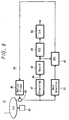
- FIG. 8 is a diagram of an example of an optical reproducing device according to the present invention.
- the present invention can be applied to optical recording medium, for example, CD, DVD, or the like.
- the present invention is directed to optical recording medium having an information recording portion or ROM portion on which the essential information of data information or the like is recorded by physical change of shape in at least one direction of depth and track width on substrate of disk, card, or sheet type, and information layer on which reflective film is mounted, wherein the reflective film is applied to form an additional recording region by thermal recording, the reflective film having a reflectance range of: 0.5 [%] ⁇ (
- the reflective film may be formed as a simple layer structure with a metal film or semiconductor film.
- a DVD configuration is used.
- the present invention is not limited to the example.
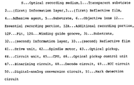
- An optical recording medium S according to the present invention shown in FIG. 1 has the following configuration.
- An information layer 2 on which information recording portion is formed by physical change of shape, or uneven pits, is formed on one major surface of a transparent substrate 1 consisting of, e.g., polycarbonate (PC) by physical change of surface or by making uneven pits, and a reflective film 3 is adhered to the entire surface of the information layer 2,
- An adhesive agent 4 consisting of, e.g., an ultraviolet setting resin is coated by, e.g., spin coat, on the substrate 1 on the side having the information layer 2.
- Another substrate 5 is superposed on the transparent substrate 1, the adhesive agent 4 is set by ultraviolet irradiation, so that both the substrates 1 and 5 are joined to each other.
- the thicknesses of both the substrates 1 and 5 are set within, e.g., about 0.6 mm each, and the total thickness of the optical recording medium S is set to be, e.g., 1.2 mm.
- These recording portions 12, i.e., the uneven pits 12P, the winding guide groove 12G, or the like are formed on a major surface of the substrate 1 by injection molding using a stamper having corresponding pits or a corresponding groove synchronously with molding of the substrate 1, or can be formed by a normal method using a so-called 2P method such that, e.g., an ultraviolet setting resin is coated on a transparent substrate, and a stamper having desired pits or a desired groove is pressed to set the ultraviolet setting resin.
- the reflective film 3 is adhesively formed on the entire surface of the information layer 2.
- the reflective film 3 causes the information layer 2 to have the function of the reflective film obtained in reading of an essential record such as data information from the recording portion 12.
- the reflective film 3 is used as a recording layer for additional recording. More specifically, an additional recording region is also constituted by the reflective film 3.
- the additional recording region may be formed in the essential recording portion 12 depending on the purpose of an additional record or may be formed out of the forming region of the essential recording portion 12. However, when the additional recording region is formed in the essential recording portion of information recording portion 12, the additional recording region is formed out of the shortest cycle portion of a change in physical shape of the essential recording portion. More specifically, the essential recording portion 12, as shown in FIG. 2, employs a recording manner obtained by formation of the uneven pits 12P, an additional recording portion 12A is formed in a pit portion consisting of a recessed portion or a projection portion or between the pits except for the shortest uneven pitch portion of the uneven pits 12P. As shown in FIG.
- the additional recording portion 12A can be formed in, e.g., the winding guide groove 12G except for the shortest cycle portion of the cycle of a reciprocal change in the direction of track width.
- the reflective film 3 is made of a metal film or a semiconductor film, the reflectance of which can be varied in a predetermined range for the aforementioned reading beam due to thermal recording by for example laser irradiation.
- An example of reflective film 3 is constituted by an Al alloy film consisting of Al 100-x X x , and the X is at least one type of element selected from Ge, Ti, Ni, Si, Tb, Fe, and Ag.
- a composition x [atomic %] of entire X in the Ag alloy film is set within the range of 5 ⁇ x ⁇ 50 [atomic %].
- reflective film 3 is made of Al-alloy film of Al 100-x-z X x Z z , the X being at least one element selected from Ge, Ti, Ni, Si, Tb, Fe, and Ag, the Z being at least one element beside the X selected from those elements, the composition rate x of an element or elements X in Al-alloy being selected as 4 ⁇ x ⁇ 50[atomic%], and the composition rate z of an element or elements Z in Al-alloy being selected as 0 ⁇ z ⁇ 5[ atomic%].
- the reflective film 3 is constituted by an Ag alloy film consisting of Ag 100-x X x
- the X is at least one type of element selected from Ge, Ti, Ni, Si, Tb, Fe, and Al.
- a composition x of entire X in the Ag-Al alloy film is set within the range of 5 ⁇ x ⁇ 50 [atomic %].
- reflective film 3 is made of Ag-alloy film of Ag 100-x-z X x Zz, the X being at least one element selected from Ge, Ti, Ni, Si, Tb, Fe, Cr, Al, and Au, the composition rate x of an element or elements X in Ag-alloy being selected as 5 ⁇ x ⁇ 50[atomic%], the Z being at least one element beside the X selected from those elements, and the composition rate z of an element or elements Z in Ag-alloy being selected as 0 ⁇ z ⁇ 5[ atomic%].
- reflective film 3 is made of Cu-alloy film of Cu 100-x X x , the X being at least one element selected from Al, Ti, Cr, Ni and Fe, and the composition rate x of an element or elements X in Cu-alloy being selected as 5 ⁇ x ⁇ 40[atomic%].
- reflective film 3 is made of Cu-alloy film of Cu 100-x-z X x Z z , the X being at least one element selected from Al, Ti, Cr, Ni and Fe, the composition rate x of an element or elements X in Cu-alloy being selected as 5 ⁇ x ⁇ 40[ atomic%], the Z being at least one element beside the X selected from those elements, and composition rate z of an element or elements Z in Cu alloy being selected as 0 ⁇ z ⁇ 5[atomic%].
- reflective film 3 may be made of Si of semiconductor materials.
- Si means the one having an purity of Si as much as that of typical semiconductor material and it allows to include other elements as much as semiconductor material.
- the reflective film 3 can be formed by, e.g., a sputtering method, e.g., a magnetron sputtering method.
- a sputtering method e.g., a magnetron sputtering method.
- exhaustion is performed such that the degree of vacuum in a sputtering device is a desired degree of vacuum or less, and sputtering is performed.
- the film thickness of the reflective film 3 is selected under the control of input power and time of the sputtering.
- the thickness of the reflective film was set at 50 nm
- a light source used in recording and reproducing was a semiconductor laser having a wavelength of 660 nm.
- a laser beam was irradiated from the transparent substrate 1 side through an objective lens 6.
- the numerical aperture N.A. of the objective lens 6 was 0.60
- a linear speed in recording was 1.5 m/sec
- recording was performed by continuous light.
- the transparent substrate 1 is constituted by a polycarbonate (PC) substrate in which a guide groove is formed by injection molding.
- a change in reflectance R s which can be reproduced i.e., not less than 0.5 % can be obtained by selecting the composition of Ge. More specifically, it is understood that recording can be performed to the reflective film.
- the recording information is recorded in the form of an edge position in the direction of running of the pits.
- the edge position is performed by detecting a zero cross position of a signal after the offset of a reproduction output signal such as asymmetry is corrected. Therefore, additional recording may be performed by using any position in the pit string without influencing the zero cross detection as an additional recording region to form an additional recording portion. More specifically, since a ratio of a signal output in a pit string having the shortest cycle in the pit string to an output obtained from a pit string having the longest cycle is about 0.1 to 0.3, a shift at the edge portion may be generated by a fine change in reflectance. As shown in FIG. 2, the additional recording portion 12A is preferably formed on a portion except for the shortest cycle portion such that the additional recording portion 12A does not influence the edge information of the recording portion 2.
- a fine change occurs on the basis of a change in reflectance of the additional recording portion 2, i.e., an increase or decrease in reflectance as indicated by a broken line with respect to a reproduction output obtained by, e.g., recording pits indicated by a solid line in FIG. 5. Therefore, when the fine change is detected, the small detection output can be used as a reproduction signal of additional recording.
- the additional recording signal is actually low in density and low in band, and, furthermore, the same signals are recorded in a plurality of additional recording regions in, e.g., additional recording, e.g., a reproducing method such as reproduction at a plurality of positions which is different from a conventional method is applied, so that the additional record can be stably reproduced when a change in reflectance related to the additional recording is not less than 0.5%.
- additional recording e.g., a reproducing method such as reproduction at a plurality of positions which is different from a conventional method is applied, so that the additional record can be stably reproduced when a change in reflectance related to the additional recording is not less than 0.5%.
- the change in reflectance R s is desirably set at 10% or less.
- a change in reflection R s related to the additional recording is desirably set at not less than 0.5% and not more than 10%.
- Table 1 and table 2 illustrate reflective film compositions in which a change R s of ⁇ 0.5% with respect to a reflectance before recording and reflectances R o [%], recording powers [mW], and film thicknesses [nm] obtained in this case before recording.
- the reflectances may change to some extent.
- a metal having a high heat conductivity of single metals such as Al, Ag, Au, and Cu or a material such as W, Mo, Ta, or Pt which has an extremely high melting point and a high temperature at which atoms move
- a recording temperature at which a change in reflectance R s of not less than 0.5% is obtained cannot be easily obtained by a recording power using a semiconductor laser.
- the recording temperature damages the surface of the plastic substrate itself of the transparent substrate 1, and information reproduction by the pits may be influenced.
- a reflective film consisting of an alloy of two or more elements which is obtained by adding one or more type of element selected from Ge, Ti, Ni, Si, Tb, Fe, and Ag of 4 to 50 [atomic %] to the base material or an alloy of two or more elements which is obtained by adding one or more type of element selected from Ge, Ti, Ni, Si, Tb, Fe, Cr, Al and Au to Ag serving as a base material, so that recording which can obtain a change in reflectance of not less than 0.5% at a power in a semiconductor laser, i.e., 50 [mW] or less, furthermore, 30 [mW] or less.
- an Al alloy film consisting of Al 100-x-z X x Z z or an Ag alloy film consisting of Ag 100-x-z X x Z z i.e., in the Al alloy film or the Ag alloy film, as still another element Z, e.g., one or more type of element selected from B, C, N, O, Mg, V, Cr, Mn, Co, Cu, Zn, Ga, As, Se, Y, Zr, Nb, Mo, Pd, In, Sn, Sb, Te, Lu, Hf, Ta, W, Ir, Pt, Au, Pb, Bi, La, Ce, Nd, Sm, Gd, Dy, Ho, and Er is added, so that a required change in reflectance can be obtained by, e.g., a semiconductor laser.
- the added quantity of the element Z is small, i.e., the composition z can be set within 0 ⁇ z ⁇ 5 [atomic %].
- the reflective film3 having Cu of Cu 100-xXx as a mother material, by adding at least one element selected from Al, Ti, Cr, Ni, and Fe and selecting 5 ⁇ x ⁇ 40[ atomic%] as composition rate x of an element or elements X in Cu alloy, similarly, such a recording can be achieved that a change in reflectance Rs of more than 0.5% can be obtained at a power in semiconductor laser of less than 50 [mW], or 30[mW].
- the reflective film3 having Cu of Cu 100-x-zXxZz as a mother material by adding at least one element selected from Al, Ti, Cr, Ni, and Fe and at least one element selected from B, C, N, O, Mg, V, Cr, Mn, Co, Cu, Zn, Ga, As, Se, Y, Zr, Nb, Mo, Pd, In, Sn, Sb, Te, Lu, Hf, Ta, W, Ir, Pt, Au, Pb, Bi, La, Ce, Nd, Sm, Gd, Dy, Ho and Er and by selecting 0? ⁇ x?5[atomic%] as the composition rate z of an element or elements Z in Cu alloy, similarly, such a recording can be achieved that a change in reflectance R s of more than 0.5% can be obtained at a power in semiconductor laser of less than 50 [mW], or 30[mW].
- a DVD configuration having the single information layer 2 is used.
- an optical recording medium configuration such as a DVD having, e.g., a two-layer information layer obtained such that a second substrate 31 having a second information layer 32 on which a second reflective film 33 is formed is superposed on the information layer 2 to be joined to the information layer 2 by a transparent adhesive agent 4 may be used.
- a reflectance of the first information layer 2 may be set at, e.g., about 10 to 40%.
- the film thickness of the first reflective film 3 is set at about 5 nm to 20 nm.
- the first reflective film 3 may be made of for example Si-semiconductor film.
- Si-semiconductor may include other elements as impurities as described above.
- the first reflective film 3 may be made of Ag-alloy film of Ag100-xXx, the X being at least one element selected from Ge, Ni, Si, Tb, Fe, Al, Ti, Pd, Cr and Au, and the composition rate x of an element or elements X in Ag-alloy film being selected to 4.5 ⁇ x ⁇ 40[atomic%].
- the first reflective film 3 may be made of Ag-alloy of Ag100-x-zXxZz, the X being at least one element selected from Ge, Ni, Si, Tb, Fe, Al, Ti, Pd, Cr and Au, the Z being at least one element besides the X selected from those elements and the composition rate z of an element or elements Z in Ag-alloy film being selected to 4.5 ⁇ x ⁇ 40[atomic%].
- the first reflective film 3 may be made of Au-alloy of Au 100-x X x , the X being at least one element selected from Ti, Ge, Ni, Tb, Fe, Al, Pd, and Cr, and the composition rate x of an element or elements X in Au-alloy film being selected to 4.5 ⁇ x ⁇ 40[atomic%].
- first reflective film 3 can achieve such a recording that R s is more than 0.5% by semiconductor laser irradiation.
- Fig. 7 is a graph showing measurement results of the relationships between recording laser power [mW] and reflectance [%], in which ⁇ shows the measurement result of Si-film having a thickness of 18 nm and • shows the measurement results of Al92.6 Pd0.9 Ti6.5-film.
- the thickness of the reflective film 3 in the single information layer structure described in FIG. 1 and the thickness of the second reflective film 33 in the two-layer information layer structure in FIG. 6 are desirably set at 20 nm to 70 nm.
- optical recording medium S of the present invention additional recording can be performed, so that cipher data is described in manufacturing.
- the cipher is reproduced by a reproducing device having an algorithm which can decode the cipher, it can be made impossible to reproduce an optical recording medium which is illegally copied, and the optical recording medium S can be used for many applications.
- a rental additionally records a dedicated cipher for a specific person who is permitted to rent a media so as to prevent a person except for the specific person from using the media.
- the rental can employ various application manners such that a medium management, records of a game end point in game software, the mark of a reproduced position, and user information, a record of a reproduction current, and a function of reading these records are added to a recording/reproducing device by, e.g., a general user.
- An optical recording device comprises an optical recording means for the optical recording medium according to the present invention described above.
- the optical recording medium has an irradiation means of a laser beam modulated depending on additional recording information for the optical recording medium.
- the optical can perform additional recording by thermal recording in which the reflective film 3 is transformed by irradiation of the laser beam to change the reflectance of the reflective film.
- An optical reproducing device comprises an optical reproducing means for an optical recording medium on which the additional recording according to the present invention described above.
- the optical reproducing means has a reproduction light irradiation means for irradiating reproduction light on the optical recording medium and detection means for detecting return light from the reflective film. The fine change of a detection output from the detection means is used as a reproduction signal of the additional recording.
- An optical recording/reproducing device comprises an optical recording means for the optical recording medium according to the present invention described above and an optical reproducing means.
- the optical recording/reproducing means has an irradiation means for a laser beam modulated depending on additional recording information for the optical recording means. Additional recording is performed by thermal recording in which the reflective film is transformed by irradiation of the laser beam to change the reflectance of the reflective film.
- the optical reproducing means has a reproduction light irradiation means for irradiating reproduction light on the optical recording medium and detection means for detecting return light from the reflective film, and the fine change of a detection output from the detection means is extracted as a reproduction signal of the additional recording.
- the optical recording/reproducing device performs recording/reproducing for the optical recording medium S constituted by a DVD described in FIG. 1.
- the operation recording/reproducing device has a drive unit 41 for rotationally driving the optical recording medium S.
- the rotational drive of the drive unit 41 is performed by a spindle motor 42.
- the spindle motor 42 is controlled by a servo circuit (not shown) to control the rotating speed of the optical recording medium S.
- an optical pickup 43 constituted by an optical recording means for performing the additional recording described above and serving as an optical reproducing means for reproducing an additional record on the optical recording medium S.
- the optical pickup 43 is designed to be moved by a thread mechanism (not shown) in a direction parallel to the radial direction of the optical recording medium S.
- This optical pickup 43 comprises an optical irradiation means having a semiconductor laser as in an optical pickup configuration in a conventional optical recording/reproducing device.
- a laser beam from the semiconductor laser is designed to be convergently irradiated on the optical recording medium S by an objective lens.
- the optical irradiation means comprises a modulation means for modulating the quantity of irradiated light of the laser beam for the optical recording medium depending on additional recording information, e.g., a light intensity modulation element arranged on the optical path of the laser beam, or a modulation means (not shown) for controlling the power of the semiconductor laser, so that a recording laser beam for the optical recording medium can be irradiated.
- a modulation means for modulating the quantity of irradiated light of the laser beam for the optical recording medium depending on additional recording information, e.g., a light intensity modulation element arranged on the optical path of the laser beam, or a modulation means (not shown) for controlling the power of the semiconductor laser, so that a recording laser beam for the optical recording medium can be irradiated.
- the optical pickup 43 has a detection unit for detecting return light of the laser beam from the optical recording medium S to extract the return light as an electric output.
- a tracking error signal and a focusing error signal are obtained in the optical pickup 43.
- tracking servo and focusing servo are performed.
- a circuit unit 44 for controlling an optical recording operation and an optical reproducing operation of the optical pickup 43 is arranged.
- the circuit unit 44 is constituted by, e.g., a CPU (Central Processing Unit) 45, a control unit 46 of the optical pickup 43, a binarizing circuit 47, a decode circuit 48, an ECC (Error Correcting Code) circuit 49, a digital-analog conversion circuit (D-A) 50, and a mark detection circuit 51.
- a CPU Central Processing Unit
- control unit 46 of the optical pickup 43 e.g., a control unit 46 of the optical pickup 43, a binarizing circuit 47, a decode circuit 48, an ECC (Error Correcting Code) circuit 49, a digital-analog conversion circuit (D-A) 50, and a mark detection circuit 51.
- ECC Error Correcting Code
- the optical recording medium S has an additional recording portion 12A in which various ciphers and a mark, e.g., a mark for detecting illegal use are recorded in, e.g., a predetermined portion by a manufacturer.
- a required signal is given to the control unit 46 of the optical pickup 43 by a control signal from the CPU 45, and a laser beam from the optical pickup 43 is irradiated on a position where the additional recording position of the optical recording medium S is irradiated, i.e., a predetermined position in which a mark is described.
- the laser beam is set to be a laser output applied to the mark detection.
- a reproduction output obtained by the mark of the additional recording portion is extracted from the optical pickup 43, the reproduction output is input to the mark detection circuit 51, and the mark detection output is input to the CPU 45.
- the optical pickup control unit is controlled to stop, e.g., a reproducing operation.
- a laser beam of the optical pickup 43 is irradiated on a predetermined essential recording portion 12 of the optical recording medium S by a control signal from the optical pickup control unit 46 in response to a command from the CPU 45 to perform a reproducing operation. More specifically, for example, a read signal of the recording portion 12 from the optical pickup 43 is input to the optical pickup 43. In this manner, the signal is binarized by a predetermined slice level to obtain a binary signal, and the binary signal is decoded by the decode circuit 48 to generate reproduction data.
- the reproduction data is input to the ECC circuit 49, and is subjected to an error correction process by using an error correction code added during coding in a recording state, and the reproduction data is converted into an analog signal by the digital-analog conversion circuit 50.
- Additional recording for the optical recording medium S is performed by the following manner. That is, as described above, an irradiation position of a laser beam is set to be a predetermined position where the additional recording is performed, recording information such as recording information from the CPU 45 or recording information of another recording information signal source (not shown) is input to the control unit 46, and a laser beam of the optical pickup 43 is modulated by a control signal from the control unit 46.
- the optical recording device according to the present invention having the reproducing function and the recording function for the optical recording medium S is described.
- the optical recording device according to the present invention or the optical reproducing device according to the present invention is constituted as a device having any one of the optical recording function and the optical reproducing function of the configuration described above.
- the optical recording medium, the optical recording/ reproducing device, the optical recording device, and the optical reproducing device according to the present invention are not limited to devices applied to the so-called DVD.
- the medium and the devices can be applied to an optical disk such as a CD having a ROM portion and an optical recording medium having another shape.
- the optical recording medium according to the present invention described above in a ROM type optical recording medium, can record an arbitrary record such as a reproduced position, the mark of a game end point in game software, the record of personal information on a user side, the password of a specific renter by a rental, and a reproduction count by making it possible to perform additional recording on, e.g., the user side.
- a management code is described to make it possible to specify a manufacturer, decide whether an optical recording medium is illegally copied or not, and perform management or the like.
- reproduction is performed by a reproducing device having an algorithm which can decode the cipher, so that an illegally copied optical recording medium can be prevented from being reproduced. Therefore, many applications can be achieved.
- An optical recording medium according to the present invention, a recording layer having a special configuration is not formed as a recording layer for performing the above additional recording.
- the reflective film By setting the composition of a reflective film formed in an essential information layer, the reflective film itself also constitutes an additional recording region for performing the additional recording.
- optical recording media according to the present invention can be manufactured in mass production without increasing the number of manufacturing steps and without using toxic materials.
- the optical recording media can be inexpensively manufactured with mass-productivity and cost which are equal to those of a conventional ROM type optical recording media.
- a recording method for an optical recording medium according to the present invention can perform optical recording by using a semiconductor laser. For this reason, a configuration depending on the object of the additional recording is used in a recording device using the recording method, i.e., an optical recording device. However, the optical recording device does not requires a special configuration.
- an optical reproducing method for an optical recording medium according to the present invention can also perform optical reproduction by using a semiconductor laser. For this reason, the optical reproducing method has a configuration depending on the object of additional recording. However, since reading can be basically performed by the semiconductor layer as in a conventional optical recording/ reproducing device, a simple configuration can be achieved.
Landscapes
- Engineering & Computer Science (AREA)
- Computer Security & Cryptography (AREA)
- Signal Processing (AREA)
- Multimedia (AREA)
- Optical Record Carriers And Manufacture Thereof (AREA)
- Optical Recording Or Reproduction (AREA)
- Optical Head (AREA)
Abstract
Description
| Material Component (at %) | Reflectance before Recording (%) | Recording power (mW) | Film Thickness (nm) |
| Al88.8Ge11.2 | 73.5 | 9.2 | 50 |
| Al84.0Ge16.0 | 71.0 | 7.5 | 50 |
| Al80.0Ge20.0 | 61.0 | 3.2 | 50 |
| Al72.4Ge27.6 | 51.0 | 2.3 | 50 |
| Al61.2Ge38.8 | 42.0 | 1.9 | 50 |
| Al53.1Ge46.9 | 38.5 | 1.7 | 50 |
| Al92.3Ti7.7 | 74.4 | 9.5 | 50 |
| Al89.0Ti11.0 | 68.0 | 6.5 | 50 |
| Al85.8Ti14.2 ○ | 62.6 | 3.5 | 50 |
| Al77.2Ti22.8 | 48.0 | 7.5 | 50 |
| Al69.3Ti30.7 | 45.0 | 4.0 | 50 |
| Al79.5Ni20.5 | 50.7 | 3.5 | 50 |
| Al65.9Ni34.1 | 33.5 | 3.5 | 50 |
| Al56.3Ni43.7 ○ | 41.3 | 3.0 | 50 |
| Al88.5Si11.5 | 64.0 | 7.0 | 50 |
| Al82.8Si17.2 | 60.0 | 2.8 | 50 |
| Al76.3Si23.7 | 61.6 | 2.4 | 50 |
| Al70.7Si29.3 | 61.8 | 2.4 | 50 |
| Al92.0Tb8.0 ○ | 63.0 | 4.0 | 38 |
| Al88.0Tb12.0 ○ | 57.5 | 3.6 | 38 |
| Al88.0Fe12.0 ○ | 64.0 | 5.5 | 38 |
| Al85.7Ag14.3 | 74.5 | 9.2 | 40 |
| Al81.3Ag18.7 | 72.4 | 8.0 | 40 |
| Al77.0Ag23.0 | 71.9 | 8.0 | 40 |
| Ag70.9Al29.7 | 66.4 | 7.0 | 40 |
| Ag87.4Al12.6 | 65.3 | 9.0 | 40 |
| Ag79.4Ge20.8 | 65.3 | 5.4 | 40 |
| Ag72.0Gc28.0 | 55.6 | 3.7 | 40 |
| Ag65.8Ge34.2 | 50.9 | 3.5 | 40 |
| Ag89.0Ti11.0 | 70.0 | 9.5 | 40 |
| Ag82.6Ti17.4 | 66.3 | 7.0 | 40 |
| Material Component (at %) | Reflectance before Recording (%) | Recording power (mW) | Film Thickness (nm) |
| Al80.0Cu20.0 | 71.5 | 9.4 | 50 |
| Al73.7Cu26.3 | 64.3 | 8.0 | 50 |
| Al68.6Cu31.4 | 58.5 | 7.4 | 50 |
| Al66.8Cu30.0Ti3.2 | 63.2 | 7.0 | 50 |
| Al65.2Cu29.0Ti5.8 | 60.8 | 6.5 | 50 |
| Al66.8Cu30.3Cr2.9 | 62.5 | 7.1 | 50 |
| Al65.5Cu28.0Cr6.5 | 58.9 | 6.0 | 50 |
| Cu90.6Al9.4 | 68.9 | 9.8 | 50 |
| Cu87.6Al12.4 | 67.0 | 9.0 | 50 |
| Cu82.5Al17.5 | 68.5 | 8.0 | 50 |
| Cu82.7Al6.8Ti10.5 | 68.2 | 6.5 | 50 |
| Cu80.4Al6.6Ti13.0 | 65.2 | 5.2 | 50 |
| Cu82.3Al12.4Ti5.3 | 66.0 | 7.0 | 50 |
| Cu77.8Al14.2Ti8.0 | 64.5 | 6.1 | 50 |
| Cu76.0Al19.5Ti4.5 | 66.8 | 6.6 | 50 |
| Al70.3Al25.4Ti4.3 | 68.3 | 5.0 | 50 |
| Al95.5Ti4.5 | 77.5 | 0.3 | 50 |
| Al95.2Ti3.8Ni1.0 | 77.2 | 9.8 | 50 |
| Si ○ | 23.1 | 3.6 | 15 |
| Si ○ | 26.5 | 3.5 | 18 |
| Ag95.5Ti4.5 ○ | 31.5 | 6.7 | 13 |
| Ag95.1Pd0.9Ti4.0 ○ | 31.0 | 6.8 | 13 |
| Ag92.6Pd0.9Ti6.5 ○ | 30.6 | 5.9 | 13 |
| Ag95.5Cr4.5 ○ | 31.4 | 6.5 | 13 |
| Ag94.6Pd0.9Cr4.5 ○ | 31.2 | 6.1 | 13 |
| Ag84.6Au10.9Ti4.5 ○ | 30.2 | 6.0 | 13 |
| Ag95.0Si5.0 | 30.7 | 7.5 | 13 |
| Au95.2Ti4.8 | 29.5 | 5.4 | 15 |
| Au93.7Ti6.3 | 28.3 | 5.0 | 15 |
In the case of Al92.6 Pd0.9 Ti6.5-film having a thickness of 13 nm, if the recording laser power is equal to or less than 5 mW, the reflectance is 30.5%. However, if it is 7 mW, the reflectance increases to 32.5% and therefore, Rs is about 6%.
Claims (21)
- An optical recording medium having an information layer with a reflective film on which an information recording portion is formed by physical change of shape at least in one direction of depth and track width, wherein
said reflective film having such an structure that additional recording can be performed by thermal recording, and that the reflectance of said reflective film changes in the range of 0.5[%]<(|R0-R1|/R0)×100[%]<17[%],
where R0 is reflectance of non-recording state and R1 is reflectance of recording state for reproducing beam. - The optical recording medium of claim 1,
characterized in that
if the additional recording region of said reflective film is at least partially overlapped with said information recording portion formed by physical change of shape, the reflectance of said reflective film changes in the range of 0.5[%]<(|R0-R1|/R0)×100[%]<10[%]. - The optical recording medium of claim 1,
characterized in that
said additional recording region is positioned in or out of recording region having said information recording portion on which said physical change of shape has been performed. - The optical recording medium of claim 1,
characterized in that
if said additional recording region is positioned in recording region having said information recording portion by physical change of shape, said additional recording region is positioned in a region other than the shortest period portion of said information recording portion. - The optical recording medium of claim 1,
characterized in that
said reflective film is made of a single layer structure consisting of metal film or semiconductor film. - The optical recording medium of claim 1,
characterized in that
said reflective film is made of Al-alloy film of Al100-x Xx, the X being at least one element selected from Ge, Ti, Ni, Si, Tb, Fe, and Ag, and the composition rate x of an element or elements X in Al-alloy being selected as 4<x<50[atomic%]. - The optical recording medium of claim 1,
characterized in that
said reflective film is made of Al-alloy film of Al 100-X-Z XxZz, the X being at least one element selected from Ge, Ti, Ni, Si, Tb, Fe, and Ag, the Z being at least one element beside the X selected from those elements, the composition rate x of an element or elements X in A1 alloy being selected as 4<x<50[ atomic%], and the composition rate z of an element or elements Z in Al alloy being selected as 0<z<5[atomic%]. - The optical recording medium of claim 1,
characterized in that
said first reflective film is made of Ag-alloy of Ag100-xXx, the X being at least one element selected from Ge, Ti, Ni, Si, Tb, Fe, Al, Cr and Au, and the composition rate x of an element or elements X in Ag-alloy film being selected to 5<x<50[atomic%]. - The optical recording medium of claim 1,
characterized in that
said first reflective film is made of Ag-alloy of Ag100-x-zXxZz, the X being at least one element selected from Ge, Ti, Ni, Si, Tb, Fe, Al, Cr and Au, the composition rate x of an element or elements X in Ag-alloy film being selected to 5<x<50[atomic%], the Z being at least one element besides the X selected from those elements and the composition rate z of an element or elements Z in Ag-alloy film being selected to 0<x<5[atomic%]. - The optical recording medium of claim 1,
characterized in that
said reflective film is made of Cu-alloy film of Cu100-x Xx, the X being at least one element selected from Al, Ti, Cr, Ni and Fe, and the composition rate x of an element or elements X in Cu-alloy being selected as 5<x<40[atomic%]. - The optical recording medium of claim 1,
characterized in that
said reflective film is made of Cu-alloy film of Cu100-x-z XxZz, the X being at least one element selected from Al, Ti, Cr, Ni and Fe, the composition rate x of an element or elements X in Cu-alloy being selected as 5<x<40[atomic%], the Z being at least one element beside the X selected from those elements, and the composition rate z of an element or elements Z in Cu-alloy being selected as 0<z<5[atomic%]. - The optical recording medium of claim 1,
characterized in that said reflective film is made of Si. - The optical recording medium of claim 1,
characterized in that said information layer has first information layer and second information layer which are laminated each other, and reproducing beam is irradiated from said first or second information layer to said first and second information layers, the first or second reflective film of said first or second information layer of the incident side of said reproducing beam being made of Si. - The optical recording medium of claim 1,
characterized in that said information layer has first information layer and second information layer which are laminated each other, and reproducing beam is irradiated from said first or second information layer to said first and second information layers,
the first or second reflective film of said first or second information layer of the incident side of said reproducing beam being made of Ag-alloy of Ag100-xXx, the X being at least one element selected from Ge, Ni, Si, Tb, Fe, Al, Ti, Pd, Cr and Au, and the composition rate x of an element or elements X in Ag-alloy film being selected to 4.5<x40[atomic%]. - The optical recording medium of claim 1,
characterized in that said information layer has first information layer and second information layer which are laminated each other, and reproducing beam is irradiated from said first or second information layer to said first and second information layers,
the first or second reflective film of said first or second information layer of the incident side of said reproducing beam being made of Ag-alloy of Ag100-x-zXxZz, the X being at least one element selected from Ge, Ni, Si, Tb, Fe, Al, Ti, Cr and Au, the composition rate x of an element or elements X in Ag-alloy film being selected to 5<x<50[atomic%], the Z being at least one element besides the X selected from those elements and the composition rate z of an element or elements Z in Ag-alloy film being selected to 0<x<5[atomic%]. - The optical recording medium of claim 1,
characterized in that said information layer has first information layer and second information layer which are laminated each other, and reproducing beam is irradiated from said first or second information layer to said first and second information layers,
the first or second reflective film being made of Au-alloy of Au100-xXx, the X being at least one element selected from Ti, Ge, Ni, Tb, Fe, Al, Pd, and Cr, and the composition rate x of an element or elements X in Au-alloy film being selected to 4.5< x<40[atomic%]. - An optical recording method for performing additional recording by thermal recording such that the reflectance is changed due to the change of property of reflective film by irradiating laser beam modulated by additional recording information signal on optical medium, said optical medium having an information layer with a reflective film on which an information recording portion is formed by physical change of shape at least in one direction of thickness and track width, said reflective film having such an structure that additional recording can be performed by thermal recording, and that the reflectance of said reflective film changes in the range of 0.5[%]<(|R0-R1|/R0)×100[%]<17[%], where R0 is reflectance of non-recording state and R1 is reflectance of recording state for reproducing beam.
- An optical reproducing method for performing reproduction of additional recording such that fine change of return beam is performed due to the change of reflectance by irradiating laser beam on optical medium, said optical medium having an information layer with a reflective film on which an information recording portion is formed by physical change of shape at least in one direction of thickness and track width, wherein
said reflective film having such an structure that additional recording can be performed by thermal recording, and that the reflectance of said reflective film changes in the range of 0.5[%]<(|R0-R1|/R0)×100[%]<17[%],
where R0 is reflectance of non-recording state and R1 is reflectance of recording state for reproducing beam. - An optical recording apparatus comprising optical recording means for optical medium, said optical medium having an information layer with a reflective film on which an information recording portion is formed by physical change of shape at least in one direction of thickness and track width, said reflective film having such an structure that additional recording can be performed by thermal recording, and that the reflectance of said reflective film changes in the range of 0.5[%]<(|R0-R1|/R0)×100[%]<17[%],
where R0 is reflectance of non-recording state and R1 is reflectance of recording state for reproducing beam, wherein said optical recording means has irradiation means for irradiating on optical medium laser beam which can be modulated in responsive to additional recording information to perform additional recording by thermal recording such that the reflectance is changed due to the change of property of reflective film by the irradiation of laser beam. - An optical reproducing apparatus comprising optical reproducing means for optical medium, said optical medium, said optical medium having an information layer with a reflective film on which an information recording portion is formed by physical change of shape at least in one direction of thickness and track width,
said reflective film having such an structure that additional recording can be performed by thermal recording, and that the reflectance of said reflective film changes in the range of 0.5[%]<(|R0-R1|/R0)×100[%]<17[%],
where R0 is reflectance of non-recording state and R1 is reflectance of recording state for reproducing beam, wherein said optical reproducing means has irradiation means for irradiating reproducing beam on optical medium and detecting means for detecting return beam from said reflective film, fine change of detecting output from said detecting means being reproduction signal of said additional recording. - An optical recording and reproducing apparatus comprising optical recording means and optical reproducing means for optical medium, said optical medium having an information layer with a reflective film on which an information recording portion is formed by physical change of shape at least in one direction of thickness and track width,
said reflective film having such an structure that additional recording can be performed by thermal recording, and that the reflectance of said reflective film changes in the range of 0.5[%]<(|R0-R1|/R0)×100[%]<17[%],
where R0 is reflectance of non-recording state and R1 is reflectance of recording state for reproducing beam, wherein said optical recording means has irradiation means for irradiating reproducing beam on optical medium and detecting means for detecting return beam from said reflective film, fine change of detecting output from said detecting means being reproduction signal of said additional recording,
said optical reproducing means has irradiation means for irradiating reproducing beam on optical medium and detecting means for detecting return beam from said reflective film, fine change of detecting output from said detecting means being reproduction signal of said additional recording.
Applications Claiming Priority (3)
| Application Number | Priority Date | Filing Date | Title |
|---|---|---|---|
| JP20817999 | 1999-07-22 | ||
| JP20817999 | 1999-07-22 | ||
| PCT/JP2000/004860 WO2001008145A1 (en) | 1999-07-22 | 2000-07-19 | Optical recording medium, optical recording method, optical reproducing method, optical recording device, optical reproducing device, and optical recording/reproducing device |
Publications (3)
| Publication Number | Publication Date |
|---|---|
| EP1122723A1 true EP1122723A1 (en) | 2001-08-08 |
| EP1122723A4 EP1122723A4 (en) | 2003-09-10 |
| EP1122723B1 EP1122723B1 (en) | 2006-10-18 |
Family
ID=16551980
Family Applications (1)
| Application Number | Title | Priority Date | Filing Date |
|---|---|---|---|
| EP00946419A Expired - Lifetime EP1122723B1 (en) | 1999-07-22 | 2000-07-19 | Optical recording medium, optical recording method, optical reproducing method, optical recording device, optical reproducing device, and optical recording/reproducing device |
Country Status (12)
| Country | Link |
|---|---|
| US (1) | US6788635B1 (en) |
| EP (1) | EP1122723B1 (en) |
| JP (2) | JP4433654B2 (en) |
| KR (1) | KR100796084B1 (en) |
| CN (1) | CN1202521C (en) |
| AT (1) | ATE343203T1 (en) |
| AU (1) | AU777695B2 (en) |
| CA (1) | CA2344926C (en) |
| DE (1) | DE60031364T2 (en) |
| MY (1) | MY124773A (en) |
| TW (1) | TW472253B (en) |
| WO (1) | WO2001008145A1 (en) |
Cited By (14)
| Publication number | Priority date | Publication date | Assignee | Title |
|---|---|---|---|---|
| US7033730B2 (en) * | 2002-06-28 | 2006-04-25 | Williams Advanced Materials, Inc. | Silver-reactive metal alloys for optical data storage and recordable storage media containing same |
| EP1746591A3 (en) * | 2005-07-22 | 2007-02-28 | Kabushiki Kaisha Kobe Seiko Sho | Silver alloy reflective films for optical information recording media, silver alloy sputtering targets therefor, and optical information recording media |
| WO2006017471A3 (en) * | 2004-08-06 | 2007-04-19 | Williams Advanced Materials In | Copper based alloys and optical media containing same |
| US7231649B2 (en) | 2002-05-31 | 2007-06-12 | Tdk Corporation | Optical recording medium and method for optically recording data in the same |
| US7321481B2 (en) | 2002-07-04 | 2008-01-22 | Tdk Corporation | Optical recording medium |
| EP1630801A4 (en) * | 2003-05-23 | 2008-03-19 | Matsushita Electric Industrial Co Ltd | OPTICAL INFORMATION RECORDING MEDIUM AND METHOD FOR PRODUCING THE SAME |
| EP1603129A4 (en) * | 2003-03-13 | 2008-03-26 | Mitsubishi Materials Corp | Silver alloy sputtering target for forming reflective layer of optical recording medium |
| EP1840892A3 (en) * | 2006-03-28 | 2008-11-19 | Kabushi Kaisha Toshiba | Optical disk, optical disk manufacturing method and optical disk reproducing method |
| US7514037B2 (en) | 2002-08-08 | 2009-04-07 | Kobe Steel, Ltd. | AG base alloy thin film and sputtering target for forming AG base alloy thin film |
| EP1953744A3 (en) * | 2007-02-01 | 2009-04-29 | Sony Disc & Digital Solutions Inc. | Read-only optical disc medium and method of fabricating the same |
| EP2053602A4 (en) * | 2006-11-22 | 2010-07-28 | Sony Corp | OPTICAL DISC DISK MEDIUM FOR REPRODUCTION ONLY AND METHOD FOR MANUFACTURING THE SAME |
| US7781146B2 (en) | 2002-11-22 | 2010-08-24 | Tdk Corporation | Optical recording medium |
| EP2028656A4 (en) * | 2006-06-15 | 2010-11-03 | Sony Corp | optical recording medium having a reflective metallic film with single writing |
| US7932015B2 (en) | 2003-01-08 | 2011-04-26 | Tdk Corporation | Optical recording medium |
Families Citing this family (38)
| Publication number | Priority date | Publication date | Assignee | Title |
|---|---|---|---|---|
| EP2259260B1 (en) * | 2001-06-08 | 2013-07-31 | SONY DADC Corporation | Optical disk medium, and data recording method and device |
| TWI254301B (en) * | 2002-04-05 | 2006-05-01 | Tdk Corp | Optical recording medium and method for optically recording information in the same |
| JP4193408B2 (en) * | 2002-04-22 | 2008-12-10 | ソニー株式会社 | Optical recording medium and method for manufacturing the same, optical recording method, and optical reproducing method |
| TWI254934B (en) | 2002-04-26 | 2006-05-11 | Tdk Corp | Optical recording medium and method for optically recording data in the same |
| ES2294284T3 (en) * | 2002-05-30 | 2008-04-01 | Lg Electronics Inc. | OPTICAL DISK OF HIGH DENSITY AND METHOD TO PLAY AND RECORD DATA OF THE SAME. |
| US20040038080A1 (en) * | 2002-07-01 | 2004-02-26 | Tdk Corporation | Optical recording medium and method for recording data in the same |
| JP4092147B2 (en) * | 2002-07-04 | 2008-05-28 | Tdk株式会社 | Optical recording medium and optical recording method |
| JP4282285B2 (en) * | 2002-08-12 | 2009-06-17 | Tdk株式会社 | Optical recording medium and optical recording method |
| US20040076907A1 (en) * | 2002-10-22 | 2004-04-22 | Tdk Corporation | Optical recording medium and method for manufacturing the same |
| JP2005025841A (en) * | 2003-07-01 | 2005-01-27 | Tdk Corp | Optical recording disc |
| JP2005025842A (en) * | 2003-07-01 | 2005-01-27 | Tdk Corp | Optical recording disk |
| JP2005022196A (en) * | 2003-07-01 | 2005-01-27 | Tdk Corp | Optical recording disc |
| JP2005044438A (en) * | 2003-07-22 | 2005-02-17 | Tdk Corp | Optical recording disk |
| JP2005129181A (en) * | 2003-10-27 | 2005-05-19 | National Institute Of Advanced Industrial & Technology | Optical recording disc |
| CN100411029C (en) * | 2004-02-03 | 2008-08-13 | 皇家飞利浦电子股份有限公司 | Disc with combined ROM/R area |
| JP2006281751A (en) * | 2004-04-28 | 2006-10-19 | Sony Corp | Write-once optical recording medium |
| JP3907666B2 (en) * | 2004-07-15 | 2007-04-18 | 株式会社神戸製鋼所 | Read-only optical information recording medium for laser marking |
| JP4510029B2 (en) * | 2004-10-19 | 2010-07-21 | パナソニック株式会社 | Recording / reproducing method and recording / reproducing apparatus for optical recording medium |
| MXPA06001347A (en) | 2005-02-07 | 2006-09-19 | Sony Corp | Playing apparatus and method, recording apparatus and method, optical disk producing method and optical-disk recording medium. |
| JP2006294195A (en) * | 2005-04-14 | 2006-10-26 | Kobe Steel Ltd | Ag alloy reflection film for optical information recording, optical information recording medium and ag alloy sputtering target for deposition of ag alloy reflection film for optical information recording |
| JP4201006B2 (en) * | 2005-10-31 | 2008-12-24 | ソニー株式会社 | Optical recording medium |
| JP4377877B2 (en) * | 2005-12-21 | 2009-12-02 | ソニー株式会社 | Ag alloy reflecting film for optical information recording medium, optical information recording medium, and Ag alloy sputtering target for forming Ag alloy reflecting film for optical information recording medium |
| JP4622947B2 (en) * | 2006-06-29 | 2011-02-02 | ソニー株式会社 | Optical disc and optical disc manufacturing method |
| JP4337915B2 (en) * | 2007-06-12 | 2009-09-30 | 株式会社ソニー・ディスクアンドデジタルソリューションズ | Data recording method, reproduction-only optical disc manufacturing method, and reproduction-only optical disc |
| JP4631901B2 (en) | 2007-12-11 | 2011-02-16 | ソニー株式会社 | Method for manufacturing read-only optical disc medium, read-only optical disc medium |
| JP2009146465A (en) | 2007-12-11 | 2009-07-02 | Sony Corp | Read-only optical disc media |
| JP5331420B2 (en) * | 2008-09-11 | 2013-10-30 | 株式会社神戸製鋼所 | Read-only optical information recording medium and sputtering target for forming a transflective film of the optical information recording medium |
| EP2187393A1 (en) * | 2008-11-13 | 2010-05-19 | Thomson Licensing | Optical recording medium with write-once and rewritable properties |
| KR20110128198A (en) | 2009-04-14 | 2011-11-28 | 가부시키가이샤 고베 세이코쇼 | Sputtering target for reflection film formation of an optical information recording medium and an optical information recording medium |
| JP2010250888A (en) * | 2009-04-14 | 2010-11-04 | Kobe Steel Ltd | Optical information recording medium |
| JP4783857B2 (en) * | 2009-04-14 | 2011-09-28 | 株式会社神戸製鋼所 | Optical information recording medium and sputtering target |
| JP5396160B2 (en) * | 2009-05-29 | 2014-01-22 | ソニー株式会社 | Optical recording medium |
| JP5329317B2 (en) | 2009-06-30 | 2013-10-30 | ソニー株式会社 | Read-only optical disc and method for manufacturing read-only optical disc |
| US20110051584A1 (en) * | 2009-08-31 | 2011-03-03 | Moser Baer India Limited | Optical recording mediums |
| PL2492913T3 (en) * | 2009-10-22 | 2015-09-30 | Panasonic Corp | Optical information recording medium and method for producing same |
| KR20120113651A (en) | 2009-12-22 | 2012-10-15 | 파나소닉 주식회사 | Optical disc device, optical disc control method, and integrated circuit |
| KR20220033650A (en) * | 2020-09-09 | 2022-03-17 | 삼성디스플레이 주식회사 | Reflective electrode and display device having the same |
| KR102680655B1 (en) * | 2021-12-21 | 2024-07-02 | 엠에스웨이 주식회사 | low registance conductive thin film and fabrication method for the same |
Family Cites Families (19)
| Publication number | Priority date | Publication date | Assignee | Title |
|---|---|---|---|---|
| JPS60214434A (en) * | 1984-04-11 | 1985-10-26 | Ricoh Co Ltd | Optical recording medium |
| JPS63106928A (en) * | 1986-10-24 | 1988-05-12 | Hitachi Ltd | Multiplexed optical information recording medium |
| US4961077A (en) * | 1988-02-19 | 1990-10-02 | E. I. Du Pont De Nemours And Company | Method for affixing information on read-only optical discs |
| EP0329122B1 (en) | 1988-02-19 | 1993-08-11 | Philips and Du Pont Optical Company | Method for affixing information on read-only optical disks |
| JPH02306430A (en) * | 1989-05-19 | 1990-12-19 | Fujitsu Ltd | Correctable optical disk and recording and reproducing method |
| JPH0428032A (en) * | 1990-05-24 | 1992-01-30 | Daicel Chem Ind Ltd | Optical information recording medium |
| KR920002931A (en) * | 1990-07-31 | 1992-02-28 | 강진구 | Lubrication control device of hermetic scull compressor |
| KR930008455A (en) * | 1991-10-02 | 1993-05-21 | 이헌조 | Automatic Detection of Air Pollution Degree and Pollution Area Using Characteristics of Gas Sensors |
| JPH06131700A (en) | 1992-10-20 | 1994-05-13 | Mitsubishi Plastics Ind Ltd | Optical recording medium |
| JPH0721585A (en) * | 1993-06-30 | 1995-01-24 | Sanyo Electric Co Ltd | Optical disk and optical disk device |
| JP3291141B2 (en) | 1994-09-29 | 2002-06-10 | 日本コロムビア株式会社 | Optical disk with copy protection pattern |
| JP3503767B2 (en) | 1994-10-21 | 2004-03-08 | 日本ビクター株式会社 | Optical recording medium |
| JPH103186A (en) * | 1996-03-19 | 1998-01-06 | Xerox Corp | Electrostatic photographic printing machine, and monitoring/controlling method for electric parameter on image forming surface |
| JPH09259470A (en) | 1996-03-21 | 1997-10-03 | Toshiba Corp | Laminating information recording medium |
| JPH09306026A (en) | 1996-05-10 | 1997-11-28 | Sony Disc Technol:Kk | Optical disk and formation of light transmissible layer of optical disk |
| JPH10208268A (en) * | 1997-01-21 | 1998-08-07 | Matsushita Electric Ind Co Ltd | Optical disk marking apparatus and method, and optical disk |
| JPH1125463A (en) * | 1997-07-07 | 1999-01-29 | Sanyo Electric Co Ltd | Optical disk, optical disk recording/reproducing device and data recording method |
| JP3454410B2 (en) * | 1997-12-26 | 2003-10-06 | ソニー株式会社 | Optical disk recording device, optical disk recording method, optical disk and optical disk reproducing device |
| JP3034497B2 (en) * | 1998-05-25 | 2000-04-17 | 株式会社日立製作所 | Information recording / reproducing / erasing device |
-
2000
- 2000-07-19 JP JP2001513153A patent/JP4433654B2/en not_active Expired - Fee Related
- 2000-07-19 US US09/787,731 patent/US6788635B1/en not_active Expired - Fee Related
- 2000-07-19 WO PCT/JP2000/004860 patent/WO2001008145A1/en not_active Ceased
- 2000-07-19 CA CA002344926A patent/CA2344926C/en not_active Expired - Fee Related
- 2000-07-19 AT AT00946419T patent/ATE343203T1/en active
- 2000-07-19 KR KR1020017003598A patent/KR100796084B1/en not_active Expired - Fee Related
- 2000-07-19 AU AU60213/00A patent/AU777695B2/en not_active Ceased
- 2000-07-19 CN CNB008017816A patent/CN1202521C/en not_active Expired - Fee Related
- 2000-07-19 EP EP00946419A patent/EP1122723B1/en not_active Expired - Lifetime
- 2000-07-19 DE DE60031364T patent/DE60031364T2/en not_active Expired - Lifetime
- 2000-07-20 TW TW089114556A patent/TW472253B/en not_active IP Right Cessation
- 2000-07-22 MY MYPI20003359 patent/MY124773A/en unknown
-
2008
- 2008-12-22 JP JP2008326266A patent/JP4596071B2/en not_active Expired - Fee Related
Cited By (26)
| Publication number | Priority date | Publication date | Assignee | Title |
|---|---|---|---|---|
| US7231649B2 (en) | 2002-05-31 | 2007-06-12 | Tdk Corporation | Optical recording medium and method for optically recording data in the same |
| US7033730B2 (en) * | 2002-06-28 | 2006-04-25 | Williams Advanced Materials, Inc. | Silver-reactive metal alloys for optical data storage and recordable storage media containing same |
| US7321481B2 (en) | 2002-07-04 | 2008-01-22 | Tdk Corporation | Optical recording medium |
| DE10336228B4 (en) * | 2002-08-08 | 2011-03-24 | Kabushiki Kaisha Kobe Seiko Sho (Kobe Steel, Ltd.), Kobe-shi | Ag alloy based thin film, use of this film and manufacturing process for this film |
| US7722942B2 (en) | 2002-08-08 | 2010-05-25 | Kobe Steel, Ltd. | Ag base alloy thin film and sputtering target for forming Ag base alloy thin film |
| US8178174B2 (en) | 2002-08-08 | 2012-05-15 | Kobe Steel, Ltd. | Ag base alloy thin film and sputtering target for forming Ag base alloy thin film |
| DE10362283B4 (en) * | 2002-08-08 | 2018-05-30 | Kabushiki Kaisha Kobe Seiko Sho (Kobe Steel, Ltd.) | Production method for Ag alloy based film and sputtering target |
| US7871686B2 (en) | 2002-08-08 | 2011-01-18 | Kobe Steel, Ltd. | Ag base alloy thin film and sputtering target for forming Ag base alloy thin film |
| US7514037B2 (en) | 2002-08-08 | 2009-04-07 | Kobe Steel, Ltd. | AG base alloy thin film and sputtering target for forming AG base alloy thin film |
| DE10362302B4 (en) * | 2002-08-08 | 2019-07-18 | Kabushiki Kaisha Kobe Seiko Sho (Kobe Steel, Ltd.) | Electromagnetic shielding film product and manufacturing method therefor |
| US7566417B2 (en) | 2002-08-08 | 2009-07-28 | Kobe Steel, Ltd. | Ag base alloy thin film and sputtering target for forming Ag base alloy thin film |
| US7758942B2 (en) | 2002-08-08 | 2010-07-20 | Kabushiki Kaisha Kobe Seiko Sho | Ag base alloy thin film and sputtering target for forming Ag base alloy thin film |
| US8936856B2 (en) | 2002-08-08 | 2015-01-20 | Kobe Steel, Ltd. | AG base alloy thin film and sputtering target for forming AG base alloy thin film |
| US7781146B2 (en) | 2002-11-22 | 2010-08-24 | Tdk Corporation | Optical recording medium |
| US7932015B2 (en) | 2003-01-08 | 2011-04-26 | Tdk Corporation | Optical recording medium |
| EP1603129A4 (en) * | 2003-03-13 | 2008-03-26 | Mitsubishi Materials Corp | Silver alloy sputtering target for forming reflective layer of optical recording medium |
| EP1630801A4 (en) * | 2003-05-23 | 2008-03-19 | Matsushita Electric Industrial Co Ltd | OPTICAL INFORMATION RECORDING MEDIUM AND METHOD FOR PRODUCING THE SAME |
| WO2006017471A3 (en) * | 2004-08-06 | 2007-04-19 | Williams Advanced Materials In | Copper based alloys and optical media containing same |
| US7713608B2 (en) | 2005-07-22 | 2010-05-11 | Kabushiki Kaisha Kobe Seiko Sho (Kobe Steel, Ltd.) | Silver alloy reflective films for optical information recording media, silver alloy sputtering targets therefor, and optical information recording media |
| EP1746591A3 (en) * | 2005-07-22 | 2007-02-28 | Kabushiki Kaisha Kobe Seiko Sho | Silver alloy reflective films for optical information recording media, silver alloy sputtering targets therefor, and optical information recording media |
| EP1840892A3 (en) * | 2006-03-28 | 2008-11-19 | Kabushi Kaisha Toshiba | Optical disk, optical disk manufacturing method and optical disk reproducing method |
| EP2028656A4 (en) * | 2006-06-15 | 2010-11-03 | Sony Corp | optical recording medium having a reflective metallic film with single writing |
| US8187689B2 (en) | 2006-06-15 | 2012-05-29 | Sony Corporation | Optical recording medium having write once metal reflective film |
| EP2053602A4 (en) * | 2006-11-22 | 2010-07-28 | Sony Corp | OPTICAL DISC DISK MEDIUM FOR REPRODUCTION ONLY AND METHOD FOR MANUFACTURING THE SAME |
| US7969855B2 (en) | 2007-02-01 | 2011-06-28 | Sony Corporation | Read-only optical disc medium and method of fabricating the same |
| EP1953744A3 (en) * | 2007-02-01 | 2009-04-29 | Sony Disc & Digital Solutions Inc. | Read-only optical disc medium and method of fabricating the same |
Also Published As
| Publication number | Publication date |
|---|---|
| WO2001008145A1 (en) | 2001-02-01 |
| CA2344926A1 (en) | 2001-02-01 |
| TW472253B (en) | 2002-01-11 |
| CN1321306A (en) | 2001-11-07 |
| KR20010075247A (en) | 2001-08-09 |
| CA2344926C (en) | 2009-10-20 |
| KR100796084B1 (en) | 2008-01-21 |
| JP4433654B2 (en) | 2010-03-17 |
| US6788635B1 (en) | 2004-09-07 |
| AU777695B2 (en) | 2004-10-28 |
| EP1122723A4 (en) | 2003-09-10 |
| DE60031364D1 (en) | 2006-11-30 |
| AU6021300A (en) | 2001-02-13 |
| CN1202521C (en) | 2005-05-18 |
| DE60031364T2 (en) | 2007-09-20 |
| MY124773A (en) | 2006-07-31 |
| JP4596071B2 (en) | 2010-12-08 |
| EP1122723B1 (en) | 2006-10-18 |
| ATE343203T1 (en) | 2006-11-15 |
| JP2009093794A (en) | 2009-04-30 |
Similar Documents
| Publication | Publication Date | Title |
|---|---|---|
| US6788635B1 (en) | Optical recording medium, optical recording method, optical reproducing method, optical recording device, optical reproducing device, and optical recording/reproducing device | |
| JPWO2001008145A1 (en) | Optical recording medium, optical recording method, optical reproducing method, optical recording device, optical reproducing device, and optical recording and reproducing device | |
| JP4150155B2 (en) | Information recording medium, information recording method, reproducing method, recording / recording apparatus, and information reproducing apparatus | |
| EP1498883B1 (en) | Optical recording medium, manufacturing method thereof, optical recording method and optical reproduction method | |
| WO1992014245A1 (en) | Method for reproducing signal in optically recording medium | |
| WO1992015093A1 (en) | Method for reproducing signal in optically recording medium | |
| EP1111601B1 (en) | Optical disk recording and/or reproducing device, and focusing servomechanism | |
| WO1998044493A1 (en) | Recording and reproducing method for optical information recording medium and optical information recording medium | |
| JP3698905B2 (en) | Optical information recording medium, information recording method thereof, and information erasing method thereof | |
| KR100433118B1 (en) | Optical disk management system, optical disk, optical disk initialization apparatus, and optical disk recording and reproducing apparatus | |
| JP2001331942A (en) | Optical information recording/reproducing method and optical information recording/reproducing device | |
| JPH11149642A (en) | Optical recording medium and manufacturing method thereof | |
| JP3477834B2 (en) | optical disk | |
| JP4131039B2 (en) | Phase change optical recording medium | |
| Lou et al. | Optical Disk Storage | |
| JP2001110057A (en) | Method and device for reproducing optical recording information, and optical inormation recording medium | |
| JP2003109225A (en) | Optical recording medium and manufacturing method thereof | |
| JPH08138247A (en) | Optical recording medium, recording / reproducing method and apparatus thereof | |
| JP2001266408A (en) | Optical recording medium and manufacturing method thereof | |
| JPH04310629A (en) | Method and member for information recording | |
| JP2001043567A (en) | Information recording medium | |
| JPWO2001001405A1 (en) | Optical disc recording and/or reproducing device and focus servo device | |
| JP2003059098A (en) | Optical information recording medium | |
| JP2003099980A (en) | Optical information recording medium | |
| JP2000090482A (en) | Information recording medium and information recording / reproducing method using the same |
Legal Events
| Date | Code | Title | Description |
|---|---|---|---|
| PUAI | Public reference made under article 153(3) epc to a published international application that has entered the european phase |
Free format text: ORIGINAL CODE: 0009012 |
|
| 17P | Request for examination filed |
Effective date: 20010404 |
|
| AK | Designated contracting states |
Kind code of ref document: A1 Designated state(s): AT BE CH CY DE DK ES FI FR GB GR IE IT LI LU MC NL PT SE |
|
| AX | Request for extension of the european patent |
Free format text: AL;LT;LV;MK;RO;SI |
|
| A4 | Supplementary search report drawn up and despatched |
Effective date: 20030725 |
|
| RIC1 | Information provided on ipc code assigned before grant |
Ipc: 7G 11B 7/0045 B Ipc: 7G 11B 7/005 B Ipc: 7G 11B 7/00 B Ipc: 7G 11B 7/24 A |
|
| RBV | Designated contracting states (corrected) |
Designated state(s): AT DE FR GB |
|
| 17Q | First examination report despatched |
Effective date: 20040315 |
|
| GRAP | Despatch of communication of intention to grant a patent |
Free format text: ORIGINAL CODE: EPIDOSNIGR1 |
|
| GRAS | Grant fee paid |
Free format text: ORIGINAL CODE: EPIDOSNIGR3 |
|
| GRAA | (expected) grant |
Free format text: ORIGINAL CODE: 0009210 |
|
| AK | Designated contracting states |
Kind code of ref document: B1 Designated state(s): AT DE FR GB |
|
| REG | Reference to a national code |
Ref country code: GB Ref legal event code: FG4D |
|
| REF | Corresponds to: |
Ref document number: 60031364 Country of ref document: DE Date of ref document: 20061130 Kind code of ref document: P |
|
| ET | Fr: translation filed | ||
| PLBE | No opposition filed within time limit |
Free format text: ORIGINAL CODE: 0009261 |
|
| STAA | Information on the status of an ep patent application or granted ep patent |
Free format text: STATUS: NO OPPOSITION FILED WITHIN TIME LIMIT |
|
| 26N | No opposition filed |
Effective date: 20070719 |
|
| REG | Reference to a national code |
Ref country code: GB Ref legal event code: 746 Effective date: 20120703 |
|
| REG | Reference to a national code |
Ref country code: DE Ref legal event code: R084 Ref document number: 60031364 Country of ref document: DE Effective date: 20120614 |
|
| PGFP | Annual fee paid to national office [announced via postgrant information from national office to epo] |
Ref country code: AT Payment date: 20120711 Year of fee payment: 13 |
|
| REG | Reference to a national code |
Ref country code: AT Ref legal event code: MM01 Ref document number: 343203 Country of ref document: AT Kind code of ref document: T Effective date: 20130719 |
|
| PG25 | Lapsed in a contracting state [announced via postgrant information from national office to epo] |
Ref country code: AT Free format text: LAPSE BECAUSE OF NON-PAYMENT OF DUE FEES Effective date: 20130719 |
|
| PGFP | Annual fee paid to national office [announced via postgrant information from national office to epo] |
Ref country code: DE Payment date: 20140721 Year of fee payment: 15 |
|
| PGFP | Annual fee paid to national office [announced via postgrant information from national office to epo] |
Ref country code: FR Payment date: 20140721 Year of fee payment: 15 Ref country code: GB Payment date: 20140721 Year of fee payment: 15 |
|
| REG | Reference to a national code |
Ref country code: DE Ref legal event code: R119 Ref document number: 60031364 Country of ref document: DE |
|
| GBPC | Gb: european patent ceased through non-payment of renewal fee |
Effective date: 20150719 |
|
| PG25 | Lapsed in a contracting state [announced via postgrant information from national office to epo] |
Ref country code: GB Free format text: LAPSE BECAUSE OF NON-PAYMENT OF DUE FEES Effective date: 20150719 Ref country code: DE Free format text: LAPSE BECAUSE OF NON-PAYMENT OF DUE FEES Effective date: 20160202 |
|
| REG | Reference to a national code |
Ref country code: FR Ref legal event code: ST Effective date: 20160331 |
|
| PG25 | Lapsed in a contracting state [announced via postgrant information from national office to epo] |
Ref country code: FR Free format text: LAPSE BECAUSE OF NON-PAYMENT OF DUE FEES Effective date: 20150731 |