EP1122695A2 - Coin processing device capable of preventing a dishonest act by the use of forged coins - Google Patents
Coin processing device capable of preventing a dishonest act by the use of forged coins Download PDFInfo
- Publication number
- EP1122695A2 EP1122695A2 EP00309953A EP00309953A EP1122695A2 EP 1122695 A2 EP1122695 A2 EP 1122695A2 EP 00309953 A EP00309953 A EP 00309953A EP 00309953 A EP00309953 A EP 00309953A EP 1122695 A2 EP1122695 A2 EP 1122695A2
- Authority
- EP
- European Patent Office
- Prior art keywords
- coin
- path
- deposited
- primary
- stock cylinder
- Prior art date
- Legal status (The legal status is an assumption and is not a legal conclusion. Google has not performed a legal analysis and makes no representation as to the accuracy of the status listed.)
- Withdrawn
Links
- 230000000717 retained effect Effects 0.000 claims abstract description 18
- 238000000151 deposition Methods 0.000 description 2
Images


Classifications
-
- G—PHYSICS
- G07—CHECKING-DEVICES
- G07F—COIN-FREED OR LIKE APPARATUS
- G07F1/00—Coin inlet arrangements; Coins specially adapted to operate coin-freed mechanisms
- G07F1/04—Coin chutes
- G07F1/047—Coin chutes with means for temporarily storing coins
-
- G—PHYSICS
- G07—CHECKING-DEVICES
- G07D—HANDLING OF COINS OR VALUABLE PAPERS, e.g. TESTING, SORTING BY DENOMINATIONS, COUNTING, DISPENSING, CHANGING OR DEPOSITING
- G07D3/00—Sorting a mixed bulk of coins into denominations
- G07D3/14—Apparatus driven under control of coin-sensing elements
Definitions
- the present invention relates to a coin processing device for use in a vending machine.
- a vending machine generally includes a coin processing device for processing a deposited coin deposited to the vending machine.
- the coin processing device includes a coin judging part for judging whether the deposited coin is a genuine coin or a false coin, a return path for returning the false coin to a return slot of the vending machine, and a coin path for guiding the genuine coin towards either one of a change coin stock cylinder and a cashbox which are included in the vending machine.
- the change coin stock cylinder is not full, the genuine coin is sent from the coin path to the change coin stock cylinder and stored therein as each of change coins. On the other hand, if the change coin stock cylinder is full, the genuine coin is sent from the coin path to the cashbox.
- the change coin stock cylinder is arranged in a substantially vertical position. Inside the change coin stock cylinder, the change coins are stored in the manner such that a newly received coin is piled up on previously received coins. Therefore, the change coins are dispensed from the bottom of the change coin stock cylinder if necessary when an item or article is sold.
- forged coins may possibly be judged as the genuine coin and accepted in the coin processing device.
- the forged coins are stored in the change coin stock cylinder or the cashbox.
- the genuine coins are dispensed from the bottom of the change coin stock cylinder. That is, by depositing the forged coins in a vending machine and thereafter carrying out the returning operation, it is possible to obtain the genuine coins from the vending machine.
- dishonest acts making illicit use of the above-mentioned mechanism and function are prevailing.
- a coin processing device which is for processing a deposited coin deposited by a depositor and comprises a primary coin path for guiding the deposited coin, a return path for returning the deposited coin to the depositor, and a receiving apparatus for receiving the deposited coin from the primary coin path.
- the coin processing device further comprises a retaining apparatus connected to the primary coin path for temporarily retaining the deposited coin as a retained coin in the primary coin path, a first carrying apparatus connected to the retaining apparatus and the return path for carrying the retained coin from the retaining apparatus to the return path in response to request for returning the deposited coin, and a second carrying apparatus connected to the retaining apparatus and the receiving apparatus for carrying the retained coin from the retaining apparatus to the receiving apparatus in response to request for receiving the deposited coin.
- a coin processing device which is for processing a deposited coin deposited by a depositor and comprises a return path extending substantially in a vertical direction for returning the deposited coin to the depositor, a primary coin path extending along an upper portion of the return path for guiding the deposited coin, a primary stock cylinder extending along a lower portion of the return path for storing change coins, a cashbox path extending substantially in the vertical direction for collecting the deposited coin, a first local path connected between a lower portion of the primary coin path and the cashbox path for guiding the deposited coin from the primary coin path to the cashbox path, a second local path connected between a lower end of the primary coin path and the primary stock cylinder for guiding the deposited coin from the primary coin path to the primary stock cylinder, a third local path connected between the lower end of the primary coin path and the return path for guiding the deposited coin from the primary coin path to the return path, and a path control apparatus connected to the first, the second, and the
- a coin processing device which is for processing a deposited coin and comprises a coin judging unit for judging whether the deposited coin is a genuine coin or a false coin, a first distributing mechanism connected to the coin judging unit for guiding the deposited coin to a coin path for each denomination and to a return path if the deposited coin is judged by the coin judging means to be a genuine coin as an accepted coin and a false coin as an unaccepted coin, respectively, coin retaining means arranged in the middle of the coin path for temporarily retaining the deposited coin as a retained coin, and second coin distributing means for guiding the retained coin to one of a change coin stock cylinder, a cashbox path, and the return path.
- the coin processing device is used in a vending machine (not shown) for processing a deposited coin deposited by a depositor or an operator and comprises a coin slot 1.
- a coin guide 2 extends from the coin slot 1.
- a coin sensor 3 and a coin judging unit or validator 4 are arranged.
- a distributing mechanism or a coin distributing unit 5 is disposed at the end of the coin guide 2.
- Zeroth, first, second, third, fourth, and the fifth coin paths 6, 7, 8, 9, 10, and 11 extend from the coin distributing unit 5 and are for guiding the deposited coin.
- the zeroth coin path 6 is connected to a return path 12.
- the first through the fourth coin paths 7 to 10 are connected to first, second, third, and fourth change coin stock cylinders 13, 14, 15, and 16 which are for storing, as change coins, 500-yen coins, 100-yen coins, 50-yen coins, and 10-yen coins, respectively.
- the fifth coin path 11 is connected to a cashbox path connected to a cashbox 20 which is provided in the vending machine for collecting the deposited coin.
- the return path 12 is connected to a return slot 18 of the vending machine and is for returning the deposited coin to the depositor.
- the first through the fourth change coin stock cylinders 13 to 16 are connected to a change dispensing unit 19 which is, for example, disclosed in Unexamined Japanese Utility Model Publication (JP-Y2) No. H06-50059.
- the change dispensing unit 19 is connected to the return slot 18 of the vending machine and will be referred to as a coin dispensing unit for dispensing the change coins from the first through the fourth change coin stock cylinders 13 to 16.
- the first coin path 6 is referred to as a primary coin path.
- Each of the second through the fourth coin paths 7 to 10 is referred to as a secondary coin path.
- the first change coin stock cylinder 13 is referred to as a primary stock cylinder.
- Each of the second through the fourth change coin stock cylinders 14 to 16 is referred to as a secondary stock cylinder.
- the return path 12 extends substantially in a vertical direction.
- the first coin path 7 has a downstream portion which extends along an upper portion of the return path 12.
- the first change coin stock cylinder 13 extend along a lower portion of the return path 12.
- the cashbox path 17 extends substantially in the vertical direction.
- a first branch path 7a of a downward slope is branched as a first local path from a lower portion or a downstream portion of the first coin path 7.
- the first branch path 7a is connected to the cashbox path 17.
- a first baffle plate 22 is arranged at the beginning end of the first branch path 7a.
- the first baffle plate 22 is driven by a first electromagnetic solenoid 21 to advance into and retreat from the first branch path 7a.
- the first coin path 7 is provided with a second baffle plate 24 arranged on a downstream side of the branching point of the first branch path 7a.
- the second baffle plate 24 is driven by a second electromagnetic solenoid 23 to advance into and retreat from the first coin path 7.
- the second electromagnetic solenoid 23 is turned off, the second baffle plate 24 advances into the first coin path 7, as shown in Fig. 2C.
- the second electromagnetic solenoid 23 is turned on, the second baffle plate 24 retreats from the first coin path 7.
- the first coin path 7 has a downstream end branched into second and third branch paths 7b and 7c of a downward slope.
- the second branch path 7b is connected to the first change coin stock cylinder 13.
- the third branch path 7c is connected to the return path 12.
- the second and the third branch paths 7b and 7c are selectively opened or closed by a third baffle plate 25 of a swinging type.
- the third baffle plate 25 is provided with a pin 25a protruding therefrom.
- the pin 25a is inserted through a long hole 26a formed in a lever 26 which is driven by the first electromagnetic solenoid 21.
- the first baffle plate 22 advances into the first branch path 7a, as shown in Fig. 2B.
- the third baffle plate 25 opens the second branch path 7b and closes the third branch path 7c, as shown by a solid line in Fig. 2B.
- the first baffle plate 22 retreats from the first branch path 7a.
- the third baffle plate 25 closes the second branch path 7b and opens the third branch path 7c, as depicted by a dash-and-dot line in Fig. 2B.
- the second and the third branch paths 7b and 7c are referred to as second and third local paths, respectively.
- the above-mentioned components are operated under control of a controlling device (not shown).
- the coin distributing unit 5 sends unaccepted coins judged as false coins to a distributing path 6.
- the unaccepted coins are returned through the zeroth coin path 6 and the return path 12 to the return slot 18 of the vending machine.
- a combination of the coin distributing unit 5 and the zeroth coin path 6 will be referred to as a conducting unit.
- the coin distributing unit 5 distributes the 100-yen coin, the 50-yen coin, and the 10-yen coin into the coin paths 8, 9, and 10, respectively.
- the coin distributing unit 5 sends the 100-yen coin, the 50-yen coin, and the 10-yen coin to the cashbox path 17.
- a sensor not shown.
- the coin distributing device 5 sends the 500-yen coin to the coin path 7.
- the first and the second electromagnetic solenoids 21 and 23 are turned off so that the first and the second baffle plates 22 and 24 advance into the first branch path 7a and the coin path 7, respectively.
- the 500-yen coin depicted by A is inhibited by the first and the second baffle plates 22 and 24 from falling and thus retained in the first coin path 7, as shown in Figs. 2A-2C.
- a combination of the first and the second electromagnetic solenoids 21 and 23 and the first and the second baffle plates 22 and 24 is referred to as a retaining apparatus.
- the second electromagnetic solenoid 23 When a return button of the vending machine is operated to thereby request the return of the deposited coihs, the second electromagnetic solenoid 23 is turned on and then the first electromagnetic solenoid 21 is turned on. As a consequence, the second baffle plate 24 retreats from the first coin path 7 so that the 500-yen coin A falls down in the first coin path 7 downstream beyond the branching point of the first branch path 7a, as shown in Figs. 3A and 3B. As shown in Fig. 3B, the third baffle plate 25 closes the second branch path 7b and opens the third branch path 7c. As a result, the 500-yen coin A passes through the third branch path 7c and falls down into the return path 12 to be returned to the return slot 18 through the return path 12. In this event, a combination of the first and the second electromagnetic solenoids 21 and 23, the second and the third baffle plates 24 and 25, and the third branch path 7c is referred to as a first carrying apparatus.
- the change dispensing unit 19 is put into operation to thereby dispense one 100-yen coin, one 50-yen coin, and one 10-yen coin from the second through the fourth change coin stock cylinders 14 to 16, respectively, to the return slot 18.
- coins in a sum of 660 yen including the 500-yen coin A as deposited are returned.
- the 500-yen coin A as deposited is temporarily retained and, when the returning operation is performed, the 500-yen coin A as deposited is returned. It is therefore possible to prevent a dishonest act by the use of a forged 500-yen coin.
- the 500-yen coin A retained as mentioned above is sent to either one of the first change coin stock cylinder 13 and the cashbox 20.
- the second electromagnetic solenoid 23 is turned on.
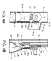
- the second baffle plate 24 retreats from the first coin path 7 so that the 500-yen coin A falls down in the first coin path 7 downstream beyond the branching point of the first branch path 7a, as shown in Figs. 4A and 4B. Since the first electromagnetic solenoid 21 is turned off, the third baffle plate 25 opens the second branch path 7b and closes the third branch path 7c.
- the 500-yen coin A passes through the second branch path 7b to be stored in the first change coin stock cylinder 13, as shown in Fig. 4B.
- the first electromagnetic solenoid 21 is turned on.
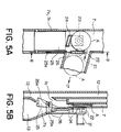
- the first baffle plate 22 retreats from the first branch path 7a, as shown in Figs. 5A and 5B.
- the second electromagnetic solenoid 23 is turned off, the second baffle plate 24 closes the first coin path 7 at the downstream side of the branch point of the first branch path 7a.
- the 500-yen coin A falls down through the first branch path 7a into the cashbox path 17 to be stored in the cashbox 20 through the cashbox path 17.
- a combination of the first and the second electromagnetic solenoids 21 and 23 and the first and the second baffle plates 22 and 24 will be referred to as a first selectively closing apparatus.
- a combination of the first electromagnetic solenoid 21 and the third baffle plate 25 will be referred to as a second selectively closing apparatus.
- a combination of the first and the second selectively closing apparatuses is referred to as a path control apparatus or a selectively closing apparatus.
- a combination of the selectively closing apparatus and the first and the second branch paths 7a and 7b is referred to as a second carrying apparatus.
- the first, the second, and the third baffle plates 22, 24, and 25 are driven by the two electromagnetic solenoids 21 and 23. It is thus possible to reduce the number of the electromagnetic solenoids in comparison with the case where those baffle plates are driven by different electromagnetic solenoids. Further, the second and the third branch paths 7b and 7c are selectively opened and closed by the third baffle plate 25. It is thus possible to reduce the number of the electromagnetic solenoids in comparison with the case where those branch paths are opened and closed by different baffle plates individually advancing and retreating and these baffle plates are driven by different electromagnetic solenoids.
- the dishonest act by the use of the forged 500-yen coin is prevented.
- a dishonest act by the use of a forged 100-yen coin, 50-yen coin, or 10-yen coin can be similarly avoided.
- the second through the fourth coin paths 8 to 10 is formed into a structure similar to that of the first coin path 7 in the above-mentioned embodiment.
Landscapes
- Physics & Mathematics (AREA)
- General Physics & Mathematics (AREA)
- Control Of Vending Devices And Auxiliary Devices For Vending Devices (AREA)
Abstract
Description
Claims (11)
- A coin processing device for processing a deposited coin deposited by a depositor, comprising a primary coin path for guiding said deposited coin, a return path for returning said deposited coin to said depositor, and a receiving apparatus for receiving said deposited coin from said primary coin path, said coin processing device further comprising:a retaining apparatus connected to said primary coin path for temporarily retaining said deposited coin as a retained coin in said primary coin path;a first carrying apparatus connected to said retaining apparatus and said return path for carrying said retained coin from said retaining apparatus to said return path in response to request for returning said deposited coin; anda second carrying apparatus connected to said retaining apparatus and said receiving apparatus for carrying said retained coin from said retaining apparatus to said receiving apparatus in response to request for receiving said deposited coin.
- A coin processing device as claimed in claim 1, wherein said receiving apparatus comprises a primary stock cylinder for storing change coins and a cashbox path for permitting said deposited coin to pass therethrough, said second carrying apparatus comprising:a first local path connected between said primary coin path and said cashbox path for guiding said retained coin from said primary coin path to said cashbox path;a second local path connected between said retaining apparatus and said primary stock cylinder for guiding said retained coin from said primary coin path to said primary stock cylinder; anda selectively closing apparatus connected to said first and said second local paths for selectively closing any one of said first and said second local paths with reference to a state of said primary stock cylinder.
- A coin processing device as claimed in claim 2, further comprising a coin dispensing unit connected to said primary stock cylinder for dispensing said change coins from said primary stock cylinder.
- A coin processing device as claimed in claim 3, further comprising:a secondary coin path for guiding said deposited coin;a secondary stock cylinder connected to said secondary coin path for storing change coins; anda distributing mechanism connected to said primary and said secondary coin path for conducting said deposited coin to any one of said primary and said secondary coin paths with reference to denomination of said deposited coin, said coin dispensing unit being further connected to said secondary stock cylinder for dispensing said charge coins from said secondary stock cylinder.
- A coin processing device as claimed in claim 1, further comprising:a coin judging unit for judging whether said deposited coin is a genuine coin or a false coin; anda conducting unit connected to said coin judging unit, said primary coin path, and said return path for conducting only said false coin to said return path in accordance with a result of judgement in said coin judging unit.
- A coin processing device for processing a deposited coin deposited by a depositor, comprising:a return path extending substantially in a vertical direction for returning said deposited coin to said depositor;a primary coin path extending along an upper portion of said return path for guiding said deposited coin;a primary stock cylinder extending along a lower portion of said return path for storing change coins;a cashbox path extending substantially in said vertical direction for collecting said deposited coin;a first local path connected between a lower portion of said primary coin path and said cashbox path for guiding said deposited coin from said primary coin path to said cashbox path;a second local path connected between a lower end of said primary coin path and said primary stock cylinder for guiding said deposited coin from said primary coin path to said primary stock cylinder;a third local path connected between the lower end of said primary coin path and said return path for guiding said deposited coin from said primary coin path to said return path; anda path control apparatus connected to said first, said second, and said third local paths for controlling said first, said second, and said third local paths to open any one of said first, said second, and said third local paths.
- A coin processing device as claimed in claim 6, wherein said path control apparatus comprises:a first selectively closing apparatus connected to said first and said second local paths for selectively closing any one of said first and said second local paths; anda second selectively closing apparatus connected to said second and said third local paths for selectively closing any one of said second and said third local paths.
- A coin processing device as claimed in claim 7, further comprising a coin dispensing unit connected to said primary stock cylinder for dispensing said change coins from said primary stock cylinder.
- A coin processing device as claimed in claim 8, further comprising:a secondary coin path for guiding said deposited coin;a secondary stock cylinder connected to said secondary coin path for storing change coins; anda distributing mechanism connected to said primary and said secondary coin path for conducting said deposited coin to any one of said primary and said secondary coin paths with reference to denomination of said deposited coin, said coin dispensing unit being further connected to said secondary stock cylinder for dispensing said charge coins from said secondary stock cylinder.
- A coin processing device for processing a deposited coin, comprising:a coin judging unit for judging whether said deposited coin is a genuine coin or a false coin;a first distributing mechanism connected to said coin judging unit for guiding said deposited coin to a coin path for each denomination and to a return path if said deposited coin is judged by said coin judging means to be a genuine coin as an accepted coin and a false coin as an unaccepted coin, respectively;coin retaining means arranged in the middle of said coin path for temporarily retaining said deposited coin as a retained coin; andsecond coin distributing means for guiding said retained coin to one of a change coin stock cylinder, a cashbox path, and said return path.
- A coin processing device as claimed in claim 10, wherein said coin retaining means and said second coin distributing means are driven by two electromagnetic solenoids.
Applications Claiming Priority (2)
| Application Number | Priority Date | Filing Date | Title |
|---|---|---|---|
| JP31798499A JP2001134805A (en) | 1999-11-09 | 1999-11-09 | Coin processing equipment |
| JP31798499 | 1999-11-09 |
Publications (2)
| Publication Number | Publication Date |
|---|---|
| EP1122695A2 true EP1122695A2 (en) | 2001-08-08 |
| EP1122695A3 EP1122695A3 (en) | 2003-04-02 |
Family
ID=18094195
Family Applications (1)
| Application Number | Title | Priority Date | Filing Date |
|---|---|---|---|
| EP00309953A Withdrawn EP1122695A3 (en) | 1999-11-09 | 2000-11-09 | Coin processing device capable of preventing a dishonest act by the use of forged coins |
Country Status (2)
| Country | Link |
|---|---|
| EP (1) | EP1122695A3 (en) |
| JP (1) | JP2001134805A (en) |
Cited By (1)
| Publication number | Priority date | Publication date | Assignee | Title |
|---|---|---|---|---|
| WO2009068271A1 (en) * | 2007-11-27 | 2009-06-04 | Giesecke & Devrient Gmbh | Device and method for sorting individually fed coins |
Families Citing this family (1)
| Publication number | Priority date | Publication date | Assignee | Title |
|---|---|---|---|---|
| CN104881916B (en) * | 2015-05-21 | 2018-05-04 | 深圳市倍量电子有限公司 | Coin cleaning-sorting machine and its separating mechanism |
Family Cites Families (3)
| Publication number | Priority date | Publication date | Assignee | Title |
|---|---|---|---|---|
| DE3304336C2 (en) * | 1983-02-09 | 1985-01-17 | Scheidt & Bachmann GmbH, 4050 Mönchengladbach | Storage device for accepting and returning coins for coin-operated devices |
| EP0355238B1 (en) * | 1988-08-25 | 1993-07-28 | Scheidt & Bachmann Gmbh | Assembly of a plurality of product or service vending machines |
| DE19525597A1 (en) * | 1994-07-13 | 1996-01-18 | Atron Electronic Gmbh | Device for processing coins with coin checker |
-
1999
- 1999-11-09 JP JP31798499A patent/JP2001134805A/en active Pending
-
2000
- 2000-11-09 EP EP00309953A patent/EP1122695A3/en not_active Withdrawn
Cited By (1)
| Publication number | Priority date | Publication date | Assignee | Title |
|---|---|---|---|---|
| WO2009068271A1 (en) * | 2007-11-27 | 2009-06-04 | Giesecke & Devrient Gmbh | Device and method for sorting individually fed coins |
Also Published As
| Publication number | Publication date |
|---|---|
| JP2001134805A (en) | 2001-05-18 |
| EP1122695A3 (en) | 2003-04-02 |
Similar Documents
| Publication | Publication Date | Title |
|---|---|---|
| EP2062230B1 (en) | A coin dispensing apparatus and a coin deposit and dispensing apparatus | |
| US5156250A (en) | Liquid diverter for currency receiver | |
| US20040249501A1 (en) | Enhanced bill acceptor/dispenser for vending machines | |
| US7604107B2 (en) | Secure coin-operated machine | |
| US7014554B1 (en) | Adaptable coin mechanism | |
| JPH0534060Y2 (en) | ||
| US6702092B2 (en) | Coin assorter | |
| US6994202B1 (en) | Money acceptance method and apparatus | |
| JP3926956B2 (en) | Coin processing equipment | |
| US6607063B2 (en) | Coin discriminating and distributing mechanism | |
| JP4002055B2 (en) | Coin sorting machine | |
| EP0993661B1 (en) | Method of operating a coin mechanism | |
| JP6582225B2 (en) | Money change system in currency exchange machine and game hall | |
| US5950795A (en) | Exact change coin collection device | |
| JP2001134805A (en) | Coin processing equipment | |
| JP7835319B1 (en) | Money processing system and money processing device | |
| JPH0543155B2 (en) | ||
| JP7838705B1 (en) | Money processing device | |
| CA2528621C (en) | Enhanced bill acceptor/dispenser for vending machines | |
| JP3338760B2 (en) | Automatic change dispensing device | |
| JPH0710435Y2 (en) | Hard loan processing device | |
| JP2001109928A (en) | Coin processing equipment | |
| CA2186051C (en) | Adaptable coin mechanism | |
| CN101661643A (en) | Coin processing device | |
| JP4244506B2 (en) | Coin processing equipment |
Legal Events
| Date | Code | Title | Description |
|---|---|---|---|
| PUAI | Public reference made under article 153(3) epc to a published international application that has entered the european phase |
Free format text: ORIGINAL CODE: 0009012 |
|
| AK | Designated contracting states |
Kind code of ref document: A2 Designated state(s): AT BE CH CY DE DK ES FI FR GB GR IE IT LI LU MC NL PT SE TR |
|
| AX | Request for extension of the european patent |
Free format text: AL;LT;LV;MK;RO;SI |
|
| PUAL | Search report despatched |
Free format text: ORIGINAL CODE: 0009013 |
|
| AK | Designated contracting states |
Kind code of ref document: A3 Designated state(s): AT BE CH CY DE DK ES FI FR GB GR IE IT LI LU MC NL PT SE TR Designated state(s): AT BE CH CY DE DK ES FI FR GB GR IE IT LI LU MC NL PT SE TR |
|
| AX | Request for extension of the european patent |
Extension state: AL LT LV MK RO SI |
|
| RIC1 | Information provided on ipc code assigned before grant |
Ipc: 7G 07F 5/24 B Ipc: 7G 07F 1/04 B Ipc: 7G 07D 3/14 A |
|
| STAA | Information on the status of an ep patent application or granted ep patent |
Free format text: STATUS: THE APPLICATION IS DEEMED TO BE WITHDRAWN |
|
| 18D | Application deemed to be withdrawn |
Effective date: 20030603 |