EP1122565A1 - Fiber optic connector receptacle - Google Patents
Fiber optic connector receptacle Download PDFInfo
- Publication number
- EP1122565A1 EP1122565A1 EP01102082A EP01102082A EP1122565A1 EP 1122565 A1 EP1122565 A1 EP 1122565A1 EP 01102082 A EP01102082 A EP 01102082A EP 01102082 A EP01102082 A EP 01102082A EP 1122565 A1 EP1122565 A1 EP 1122565A1
- Authority
- EP
- European Patent Office
- Prior art keywords
- receptacle
- opening
- mounting plate
- housing
- shutter member
- Prior art date
- Legal status (The legal status is an assumption and is not a legal conclusion. Google has not performed a legal analysis and makes no representation as to the accuracy of the status listed.)
- Granted
Links
- 239000000835 fiber Substances 0.000 title claims abstract description 40
- 239000013307 optical fiber Substances 0.000 description 9
- 230000005540 biological transmission Effects 0.000 description 5
- 239000000463 material Substances 0.000 description 3
- 230000002411 adverse Effects 0.000 description 2
- 239000000428 dust Substances 0.000 description 2
- 239000000383 hazardous chemical Substances 0.000 description 2
- 230000013011 mating Effects 0.000 description 2
- 238000009825 accumulation Methods 0.000 description 1
- 230000000712 assembly Effects 0.000 description 1
- 238000000429 assembly Methods 0.000 description 1
- 239000000919 ceramic Substances 0.000 description 1
- 239000004020 conductor Substances 0.000 description 1
- 238000003780 insertion Methods 0.000 description 1
- 230000037431 insertion Effects 0.000 description 1
- 239000002991 molded plastic Substances 0.000 description 1
- 230000003287 optical effect Effects 0.000 description 1
- 239000004033 plastic Substances 0.000 description 1
Images


Classifications
-
- G—PHYSICS
- G02—OPTICS
- G02B—OPTICAL ELEMENTS, SYSTEMS OR APPARATUS
- G02B6/00—Light guides; Structural details of arrangements comprising light guides and other optical elements, e.g. couplings
-
- G—PHYSICS
- G02—OPTICS
- G02B—OPTICAL ELEMENTS, SYSTEMS OR APPARATUS
- G02B6/00—Light guides; Structural details of arrangements comprising light guides and other optical elements, e.g. couplings
- G02B6/24—Coupling light guides
- G02B6/36—Mechanical coupling means
- G02B6/38—Mechanical coupling means having fibre to fibre mating means
- G02B6/3807—Dismountable connectors, i.e. comprising plugs
- G02B6/381—Dismountable connectors, i.e. comprising plugs of the ferrule type, e.g. fibre ends embedded in ferrules, connecting a pair of fibres
- G02B6/3825—Dismountable connectors, i.e. comprising plugs of the ferrule type, e.g. fibre ends embedded in ferrules, connecting a pair of fibres with an intermediate part, e.g. adapter, receptacle, linking two plugs
-
- G—PHYSICS
- G02—OPTICS
- G02B—OPTICAL ELEMENTS, SYSTEMS OR APPARATUS
- G02B6/00—Light guides; Structural details of arrangements comprising light guides and other optical elements, e.g. couplings
- G02B6/24—Coupling light guides
- G02B6/36—Mechanical coupling means
- G02B6/38—Mechanical coupling means having fibre to fibre mating means
- G02B6/3807—Dismountable connectors, i.e. comprising plugs
- G02B6/3833—Details of mounting fibres in ferrules; Assembly methods; Manufacture
- G02B6/3847—Details of mounting fibres in ferrules; Assembly methods; Manufacture with means preventing fibre end damage, e.g. recessed fibre surfaces
- G02B6/3849—Details of mounting fibres in ferrules; Assembly methods; Manufacture with means preventing fibre end damage, e.g. recessed fibre surfaces using mechanical protective elements, e.g. caps, hoods, sealing membranes
Definitions
- This invention generally relates to the art of fiber optic connectors and, particularly, to a receptacle, such as an adapter, for receiving a fiber optic connector at one or both ends of the adapter.
- a typical optic fiber connector includes a ferrule which mounts and centers an optical fiber or fibers within the connector.
- the ferrule may be fabricated of such material as ceramic.
- a ferrule holder or other housing component of the connector embraces the ferrule and may be fabricated of such material as molded plastic.
- a spring may be disposed within the housing or ferrule holder such that the ferrule is yieldably biased forwardly for engaging another fiber-mounting ferrule of a mating connecting device.
- a pair of fiber optic connectors or a connector and another optical fiber transmission device often are mated in an adapter which centers the fibers to provide low insertion losses.
- the adapter couples the connectors together so that their encapsulated fibers connect end-to-end.
- the adapter may be an in-line component, or the adapter can be designed for mounting in an opening in a panel, backplane, circuit board or the like.
- an exposed fiber end may be damaged by adverse environmental hazards, and the accumulation of dust and dirt may impair the optical transmission capabilities of the fiber.
- Another very important problem is to protect an operator's eyes from dangerous light beams from the exposed end of an active optical fiber. For instance, an operator's eyes may be damaged from dangerous light beams exiting an unprotected receptacle or adapter.
- dust covers, end caps or spring-loaded shutters have been used to close an open end of an adapter to, thereby, cover the exposed fiber ends to protect the fiber ends from adverse environmental hazards and to prevent light energy from the fiber ends from exiting the adapter.
- One such spring-loaded shutter is pivotally mounted on the adapter adjacent the open end thereof and is pivotally movable to close and open the open end.
- the shutter member extends across the optic axis of the connector/adapter assembly when the shutter member is closed.
- the shutter member may be pivotable away from the optic axis to its open condition upon engagement by the inserted fiber optic connector.
- Such pivotally mounted shutters as described above can be mounted either on the outside or the inside of the adapter.
- the shutter cannot be mounted on the outside of the adapter for swinging outwardly to an open position because of the lack of surrounding space.
- Inside shutters cause problems because they are extremely difficult to assemble within the adapter housing, keeping in mind that fiber optic connectors, adapters and the like are very small assemblies.
- the invention herein is directed to solving these various problems, particularly by providing a unique structure for mounting a shutter inside a receptacle housing, such as inside an adapter housing.
- An object, therefore, of the invention is to provide a new and improved receptacle for receiving a fiber optic connector along an optic axis.
- the receptacle includes a housing having at least one open end for receiving the fiber optic connector inserted thereinto on the optic axis.
- An opening is provided in the housing remote from the open end.
- a shutter member is fitted through the opening and is mounted for pivotal movement toward and away from the optic axis to close and open the open end.
- the remote opening is in a side wall of the housing.
- a mounting plate is fitted in the opening and, preferably, is sized to substantially close the opening.
- the shutter member is pivotally mounted on the mounting plate and is disposed within the housing.
- a spring operatively associated between the shutter member and the mounting plate for biasing the shutter member toward a closed position.
- a self-contained shutter assembly can be provided, including the mounting plate, the shutter member and the spring.
- the mounting plate is shown herein as press-fit into the housing opening by means of at least one mounting post on the mounting plate press-fit into a mounting hole in the housing.
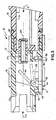
- the invention is disclosed herein as incorporated in a double-ended adapter, generally designated 10, which includes a two-part housing, generally designated 12, and a shutter assembly, generally designated 14.
- a double-ended adapter generally designated 10
- the concepts of the invention are equally applicable for a wide range of receptacles for receiving a fiber optic connector or other optical fiber transmission device along an optic axis. Therefore, the term "fiber optic connector” is used herein and in the claims hereof in a generic sense to include a variety of optical fiber transmission devices.
- adapter housing 12 is generally rectangular in cross-section and includes a first rectangular housing part 16 coupled to a second rectangular housing part 18 by means of a plurality of latch arms 20 of the first housing part latchingly engageable with a plurality of latch bosses 22 on the second housing part.
- first housing part 16 includes a pair of latch arms 24 on opposite sides thereof for latchingly engaging an appropriate structure within which receptacle 10 is to be mounted.
- both housing parts include interior aligned cylindrical bosses 26 which receive the projecting ferrules of a pair of fiber optic connectors so that their encapsulated fibers are connected end-to-end along an optic axis 28.
- First housing part 16 has an open end 30 for receiving a first fiber optic connector in the direction of arrow "A" (Fig. 3), and second housing part 18 has an open end 31 for receiving a second or mating fiber optic connector in the direction of arrow "B".
- the invention herein contemplates a unique system for mounting a shutter on the inside of a receptacle housing.
- interior shutters are extremely difficult to assemble within very small fiber optic receptacles. It is particularly difficult to assemble the shutter through the open end of the receptacle which receives the fiber optic connector.
- the invention contemplates mounting the shutter on the interior of the receptacle through an opening remote from the open end of the receptacle housing.
- first housing part 16 of the two-part housing 12 includes an opening 32 within which shutter assembly 14 is mounted.
- shutter assembly 14 is a self-contained assembly and includes a mounting plate 34, a shutter member 36 pivotally mounted to the mounting plate, a coil spring 38 for biasing the shutter member toward a closed position and a plurality of mounting posts 40 to facilitate mounting the shutter assembly within opening 32 of the adapter housing.
- Opening 32 is generally rectangular, and mounting plate 34 of shutter assembly 14 is sized and shaped to fit within the opening and substantially close the opening.
- a pair of corners 32a of the opening and a pair of corners 34a of the mounting plate are angled to prevent the shutter assembly from being fitted within the opening in the wrong direction.
- Shutter member 36 is pivotally mounted to mounting plate 34 by means of a pair of pivot shafts 42 on the shutter member received in a pair of pivot journals 44 projecting from mounting plate 34.
- Both the shutter member and the mounting plate may be fabricated of plastic material, and the pivot posts and pivot journals, respectively, may be molded integrally with those components.
- mounting posts 40 are press-fit within a plurality of mounting holes 46 (Figs. 2 and 3) of first housing part 15 inwardly of opening 32.
- Mounting posts 40 can be molded integrally with mounting plate 34.
- shutter member 36 is pivotally mounted for pivotal movement to generally close open end 30 with respect to optic axis 28.
- shutter member 36 extends across optic axis 28 when the shutter member is closed, as shown. The shutter member is pivotable away from the optic axis toward the dotted-line position upon engagement by the inserted fiber optic connector in the direction of arrow "A".
- spring 38 (Fig. 1) is operatively associated between shutter member 36 and mounting plate 34 for biasing the shutter member toward its closed position as shown in full lines in Figure 3.
- the spring is a coil spring which may surround one of the pivot shafts 42 of the shutter member.
- One end of the coil spring is captured within a channel 50 (Fig. 1) on the inside of mounting plate 34, and an opposite end 52 (Fig. 2) of the coil spring biases against the back side of shutter member 32, to maintain the coil spring in a loaded condition and to bias the shutter member toward its closed position.
Landscapes
- Physics & Mathematics (AREA)
- General Physics & Mathematics (AREA)
- Optics & Photonics (AREA)
- Mechanical Coupling Of Light Guides (AREA)
Abstract
Description
Claims (15)
- A receptacle (10) for receiving a fiber optic connector along an optic axis (28), comprising:a housing (12) having an open end (30) for receiving the fiber optic connector inserted thereinto on said optic axis, and an opening (32) remote from said open end; anda shutter member (36) fitted through said opening (32) and mounted for pivotal movement toward and away from the optic axis (28) to close and open said open end (30).
- The receptacle of claim 1, including a mounting plate (34) fitted in said opening (32) and on which the shutter member (36) is pivotally mounted.
- The receptacle of claim 2 wherein said mounting plate (34) is sized to substantially close said opening (32).
- The receptacle of claim 2, including means (40,46) for press-fitting said mounting plate (34) in said opening (32) .
- The receptacle of claim 4 wherein said press-fitting means comprise at least one mounting post (40) on the mounting plate (34) press-fit into a mounting hole (46) in the housing (12) .
- The receptacle of claim 2, including spring means (38) operatively associated between the shutter member (36) and the mounting plate (34) for biasing the shutter member toward a closed position.
- The receptacle of claim 1 wherein said opening (32) is in a side wall of the housing.
- A receptacle (10) for receiving a fiber optic connector along an optic axis (28), comprising:a housing (12) having an open end (30) for receiving the fiber optic connector inserted thereinto on said optic axis, and an opening (32) in a side wall of the housing remote from said open end;a mounting plate (34) fitted in said opening (32) and sized to substantially close the opening; anda shutter member (36) pivotally mounted on the mounting plate (34) within the housing for pivotal movement toward and away from the optic axis (28) to close and open said open end (30).
- The receptacle of claim 8, including spring means (38) operatively associated between the shutter member (36) and the mounting plate (34) for biasing the shutter member toward a closed position.
- The receptacle of claim 8, including means (40,46) for press-fitting said mounting plate (34) in said opening (32) .
- The receptacle of claim 10 wherein said press-fitting means comprise at least one mounting post (40) on the mounting plate (34) press-fit into a mounting hole (46) in the housing (12) .
- A receptacle (10) for receiving a fiber optic connector along an optic axis (28), comprising:a housing (12) having an open end (30) for receiving the fiber optic connector inserted thereinto on said optic axis, and an opening (32) remote from said open end; anda self-contained shutter assembly (14) including a mounting plate (34) fitted into said opening (32), a shutter member (36) pivotally mounted on the mounting plate for pivotal movement toward and away from the optic axis (28) to close and open said open end (32), and spring means (38) operatively associated with the shutter member (36) for biasing the shutter member toward a closed position.
- The receptacle of claim 12 wherein said mounting plate (34) is sized to substantially close said opening (32).
- The receptacle of claim 12, including means (40,46) for press-fitting said mounting plate (34) in said opening (32) .
- The receptacle of claim 14 wherein said press-fitting means comprise at least one mounting post (40) on the mounting plate (34) press-fit into a mounting hole (46) in the housing (12) .
Applications Claiming Priority (2)
| Application Number | Priority Date | Filing Date | Title |
|---|---|---|---|
| US09/498,513 US6471412B1 (en) | 2000-02-04 | 2000-02-04 | Fiber optic connector receptacle |
| US498513 | 2000-02-04 |
Publications (2)
| Publication Number | Publication Date |
|---|---|
| EP1122565A1 true EP1122565A1 (en) | 2001-08-08 |
| EP1122565B1 EP1122565B1 (en) | 2007-01-17 |
Family
ID=23981402
Family Applications (1)
| Application Number | Title | Priority Date | Filing Date |
|---|---|---|---|
| EP01102082A Expired - Lifetime EP1122565B1 (en) | 2000-02-04 | 2001-01-31 | Fiber optic connector receptacle |
Country Status (7)
| Country | Link |
|---|---|
| US (1) | US6471412B1 (en) |
| EP (1) | EP1122565B1 (en) |
| JP (1) | JP3803859B2 (en) |
| KR (1) | KR100424598B1 (en) |
| CN (1) | CN1193250C (en) |
| DE (1) | DE60125996T2 (en) |
| TW (1) | TW476470U (en) |
Cited By (6)
| Publication number | Priority date | Publication date | Assignee | Title |
|---|---|---|---|---|
| GB2388919A (en) * | 2002-04-12 | 2003-11-26 | Schott Fibre Optics | Fibre optic lighting assembly with movable protection shutter |
| EP1972974A1 (en) * | 2007-03-20 | 2008-09-24 | Ridgemount Technologies Limited | Optical fibre shutter assembly |
| WO2015158564A1 (en) * | 2014-04-16 | 2015-10-22 | Koninklijke Philips N.V. | Optical fiber calibration connector |
| WO2017081306A1 (en) * | 2015-11-13 | 2017-05-18 | CommScope Connectivity Belgium BVBA | Fiber optic connection system |
| EP3427095A4 (en) * | 2016-03-11 | 2019-10-16 | CommScope, Inc. of North Carolina | FIBER OPTIC CONNECTOR ADAPTER WITH SHUTTER HAVING SELECTIVE WAVELENGTH TRANSPARENCY |
| WO2022197638A1 (en) * | 2021-03-16 | 2022-09-22 | US Conec, Ltd | Adapter shutter assembly with shutter retention cap |
Families Citing this family (107)
| Publication number | Priority date | Publication date | Assignee | Title |
|---|---|---|---|---|
| US5883995A (en) | 1997-05-20 | 1999-03-16 | Adc Telecommunications, Inc. | Fiber connector and adapter |
| JP2002250845A (en) * | 2001-02-23 | 2002-09-06 | Hosiden Corp | Optical connector with shutter |
| US6712523B2 (en) * | 2001-06-01 | 2004-03-30 | Adc Telecommunications, Inc. | Bulkhead adapter with optical fiber for signal attenuation |
| US6688780B2 (en) | 2002-02-07 | 2004-02-10 | Amphenol Corporation | Cantilevered shutter for optical adapter |
| US6715930B2 (en) * | 2002-03-21 | 2004-04-06 | Lucent Technologies Inc. | Optical fiber shutter adapter with protective door |
| JP3946081B2 (en) * | 2002-05-02 | 2007-07-18 | Smk株式会社 | Optical connector socket |
| JP2004094109A (en) * | 2002-09-03 | 2004-03-25 | Furukawa Electric Co Ltd:The | Optical connector parts |
| JP3753688B2 (en) * | 2002-10-04 | 2006-03-08 | 日本航空電子工業株式会社 | Optical connector evening |
| US7144163B2 (en) * | 2003-01-27 | 2006-12-05 | Fujikura Ltd. | Optical connector with shutter, shutter unit, and inner piece |
| JP4084764B2 (en) | 2004-03-12 | 2008-04-30 | ホシデン株式会社 | Optical connector with shutter |
| JP4216229B2 (en) * | 2004-07-06 | 2009-01-28 | シャープ株式会社 | Optical transmission device and electronic device |
| US6994476B1 (en) * | 2004-08-09 | 2006-02-07 | Johnson Yang | Dual-use coaxial optical fiber connector |
| WO2006057088A1 (en) * | 2004-11-29 | 2006-06-01 | Seikoh Giken Co., Ltd. | Optical connector plug and optical connector |
| US7572066B2 (en) * | 2006-03-14 | 2009-08-11 | Corning Cable Systems Llc | Translucent dust cap for fiber optic adapter |
| WO2007116528A1 (en) * | 2006-04-11 | 2007-10-18 | Hamamatsu Photonics K.K. | Spot light source device |
| CN102147507B (en) * | 2010-02-05 | 2013-07-17 | 泰科电子(上海)有限公司 | Security device for interface of optical fiber adapter |
| CN102147509B (en) * | 2010-02-08 | 2013-12-11 | 鸿富锦精密工业(深圳)有限公司 | Optical fiber coupling connector and male end and female end thereof |
| US8579518B2 (en) * | 2010-03-19 | 2013-11-12 | Corning Incorporated | Optical receptacles and systems and devices including optical receptacles |
| US8727636B2 (en) * | 2010-03-19 | 2014-05-20 | Corning Incorporated | Fiber optic interface device with positionable cleaning cover |
| US9188747B2 (en) | 2011-05-23 | 2015-11-17 | Senko Advanced Components, Inc. | True one piece housing fiber optic adapter |
| CN103091789A (en) * | 2011-10-27 | 2013-05-08 | 东侑光电股份有限公司 | Protective cover for optical fiber adapter |
| US9196997B2 (en) * | 2011-11-10 | 2015-11-24 | Panduit Corp. | Shuttered LC adapter |
| US9494746B2 (en) | 2011-11-10 | 2016-11-15 | Panduit Corp. | Shuttered LC adapter |
| US8620123B2 (en) | 2012-02-13 | 2013-12-31 | Corning Cable Systems Llc | Visual tracer system for fiber optic cable |
| GB2506890B (en) * | 2012-10-10 | 2017-03-22 | Fibrefab Ltd | Fibre optic adaptor |
| JP5750807B2 (en) * | 2012-12-21 | 2015-07-22 | 本多通信工業株式会社 | Adapter for optical connector |
| US9268103B2 (en) * | 2013-05-10 | 2016-02-23 | Senko Advanced Components, Inc. | Interlockable fiber optic connector adaptors |
| US9360649B2 (en) | 2013-05-22 | 2016-06-07 | Senko Advanced Components, Inc. | Cable guide for fiber optic cables |
| JP6400892B2 (en) * | 2013-09-17 | 2018-10-03 | 三和電気工業株式会社 | LC type optical connector adapter with built-in dustproof shutter |
| US9618703B2 (en) | 2013-10-03 | 2017-04-11 | Senko Advanced Components, Inc. | Connector housing for securing an optical cable and methods of use and manufacture thereof |
| US9477049B2 (en) | 2013-12-20 | 2016-10-25 | Senko Advanced Components, Inc. | Lockable connectors and connection assemblies |
| US9535230B2 (en) | 2014-01-31 | 2017-01-03 | Senko Advanced Components, Inc. | Integrated fiber optic cable fan-out connector |
| US9297964B2 (en) | 2014-04-18 | 2016-03-29 | Senko Advanced Components, Inc. | Optical fiber connector assembly |
| US9274287B2 (en) | 2014-05-13 | 2016-03-01 | Senko Advanced Components, Inc. | Optical fiber connector and ferrule |
| US9618702B2 (en) | 2014-06-09 | 2017-04-11 | Senko Advanced Components, Inc. | Reduced-profile data transmission element connectors, adapters, and connection assemblies thereof |
| US20170212313A1 (en) * | 2014-07-21 | 2017-07-27 | Te Connectivity Nederland B.V. | Fiber optic connector and fiber optic cable assembly with fiber optic cable anchored to boot of fiber optic connector |
| US9599778B2 (en) | 2014-10-22 | 2017-03-21 | Senko Advanced Components, Inc. | Latching connector with remote release |
| US9874702B2 (en) * | 2014-10-29 | 2018-01-23 | Hewlett Packard Enterprise Development Lp | Optical connector assembly apparatus |
| US10379309B2 (en) | 2014-11-18 | 2019-08-13 | Corning Optical Communications LLC | Traceable optical fiber cable and filtered viewing device for enhanced traceability |
| US9494745B2 (en) | 2015-01-16 | 2016-11-15 | Senko Advanced Components, Inc. | Sealable communication cable connection assemblies |
| US9658409B2 (en) | 2015-03-03 | 2017-05-23 | Senko Advanced Components, Inc. | Optical fiber connector with changeable polarity |
| US10228526B2 (en) | 2015-03-31 | 2019-03-12 | Corning Optical Communications LLC | Traceable cable with side-emitting optical fiber and method of forming the same |
| US10101553B2 (en) | 2015-05-20 | 2018-10-16 | Corning Optical Communications LLC | Traceable cable with side-emitting optical fiber and method of forming the same |
| US9684139B2 (en) | 2015-05-29 | 2017-06-20 | Senko Advanced Components, Inc. | Optical fiber connector with changeable gender |
| CN107850737A (en) | 2015-07-17 | 2018-03-27 | 康宁光电通信有限责任公司 | For tracking the system and method for cable and cable for such system and method |
| EP3325876A1 (en) | 2015-07-17 | 2018-05-30 | Corning Optical Communications LLC | Systems and methods for traceable cables |
| CN105242356B (en) * | 2015-08-31 | 2017-08-04 | 中航光电科技股份有限公司 | A socket and connector assembly |
| US10101545B2 (en) | 2015-10-30 | 2018-10-16 | Corning Optical Communications LLC | Traceable cable assembly and connector |
| WO2017100114A1 (en) * | 2015-12-08 | 2017-06-15 | Panduit Corp. | Rj45 shuttered jacks and related communication systems |
| WO2017176825A1 (en) | 2016-04-08 | 2017-10-12 | Corning Optical Communications LLC | Traceable end point cable assembly |
| US10107983B2 (en) | 2016-04-29 | 2018-10-23 | Corning Optical Communications LLC | Preferential mode coupling for enhanced traceable patch cord performance |
| EP3452854A4 (en) | 2016-05-02 | 2020-04-08 | Commscope Technologies LLC | OPTICAL CONNECTOR AND ADAPTER |
| US9726830B1 (en) | 2016-06-28 | 2017-08-08 | Senko Advanced Components, Inc. | Connector and adapter system for two-fiber mechanical transfer type ferrule |
| TWI608261B (en) * | 2016-11-29 | 2017-12-11 | 普泰光電股份有限公司 | Optical fiber adapter with shutter member |
| US10078188B1 (en) | 2016-12-05 | 2018-09-18 | Senko Advanced Components, Inc. | Springless push/pull fiber optic connector |
| US10228521B2 (en) | 2016-12-05 | 2019-03-12 | Senko Advanced Components, Inc. | Narrow width adapters and connectors with modular latching arm |
| US10222561B2 (en) | 2016-12-21 | 2019-03-05 | Corning Research & Development Corporation | Light launch device for transmitting light into a traceable fiber optic cable assembly with tracing optical fibers |
| US10234614B2 (en) | 2017-01-20 | 2019-03-19 | Corning Research & Development Corporation | Light source assemblies and systems and methods with mode homogenization |
| US10185100B2 (en) | 2017-01-30 | 2019-01-22 | Senko Advanced Components, Inc | Modular connector and adapter assembly using a removable anchor device |
| US10444444B2 (en) | 2017-01-30 | 2019-10-15 | Senko Advanced Components, Inc. | Remote release tab connector assembly |
| US11333836B2 (en) | 2017-01-30 | 2022-05-17 | Senko Advanced Components, Inc. | Adapter for optical connectors |
| EP3574356A4 (en) | 2017-01-30 | 2020-08-19 | Senko Advanced Components Inc. | OPTICAL CONNECTORS WITH REVERSIBLE POLARITY |
| US10416394B2 (en) | 2017-01-30 | 2019-09-17 | Senko Advanced Components, Inc. | Fiber optic receptacle with integrated device therein |
| US10725248B2 (en) | 2017-01-30 | 2020-07-28 | Senko Advanced Components, Inc. | Fiber optic receptacle with integrated device therein incorporating a behind-the-wall fiber optic receptacle |
| US10989884B2 (en) | 2017-04-07 | 2021-04-27 | Senko Advanced Components, Inc. | Behind the wall optical connector with reduced components |
| US10359583B2 (en) | 2017-04-07 | 2019-07-23 | Senko Advanced Components, Inc. | Behind the wall optical connector with reduced components |
| US10754098B2 (en) | 2017-04-07 | 2020-08-25 | Senko Advanced Components, Inc. | Behind the wall optical connector with reduced components |
| US10209461B2 (en) | 2017-04-07 | 2019-02-19 | Senko Advanced Components | Behind the wall optical connector with reduced components |
| US10718910B2 (en) | 2017-05-03 | 2020-07-21 | Senko Advanced Components, Inc | Field terminated ruggedized fiber optic connector system |
| US10146016B1 (en) | 2017-05-10 | 2018-12-04 | Senko Advanced Components, Inc | MPO micro-latchlock connector |
| US10401576B2 (en) | 2017-05-10 | 2019-09-03 | Senko Advanced Components, Inc. | MPO micro-latch-lock connector |
| US10295759B2 (en) | 2017-05-18 | 2019-05-21 | Senko Advanced Components, Inc. | Optical connector with forward-biasing projections |
| US10359576B2 (en) | 2017-06-15 | 2019-07-23 | Senko Advanced Components, Inc. | SC low profile connector with optional boot |
| US11822133B2 (en) | 2017-07-14 | 2023-11-21 | Senko Advanced Components, Inc. | Ultra-small form factor optical connector and adapter |
| US10281668B2 (en) | 2017-07-14 | 2019-05-07 | Senko Advanced Components, Inc. | Ultra-small form factor optical connectors |
| US12001064B2 (en) | 2017-07-14 | 2024-06-04 | Senko Advanced Components, Inc. | Small form factor fiber optic connector with multi-purpose boot |
| US10718911B2 (en) | 2017-08-24 | 2020-07-21 | Senko Advanced Components, Inc. | Ultra-small form factor optical connectors using a push-pull boot receptacle release |
| US10641972B2 (en) | 2017-08-17 | 2020-05-05 | Senko Advanced Components, Inc | Anti-jam alignment sleeve holder or connector housing for a ferrule assembly |
| US11048051B2 (en) * | 2017-10-17 | 2021-06-29 | Commscope Technologies Llc | Shutter configuration for a fiber optic connector port with modular fiber carriers; and connection system |
| US10444442B2 (en) | 2017-11-03 | 2019-10-15 | Senko Advanced Components, Inc. | MPO optical fiber connector |
| US11002923B2 (en) | 2017-11-21 | 2021-05-11 | Senko Advanced Components, Inc. | Fiber optic connector with cable boot release having a two-piece clip assembly |
| US10539758B2 (en) | 2017-12-05 | 2020-01-21 | Corning Research & Development Corporation | Traceable fiber optic cable assembly with indication of polarity |
| US10539747B2 (en) | 2017-12-05 | 2020-01-21 | Corning Research & Development Corporation | Bend induced light scattering fiber and cable assemblies and method of making |
| CN115201974B (en) * | 2017-12-19 | 2024-04-30 | 美国康涅克有限公司 | Miniature duplex connector with push-pull polarity mechanism and carrier |
| US11112566B2 (en) | 2018-03-19 | 2021-09-07 | Senko Advanced Components, Inc. | Removal tool for removing a plural of micro optical connectors from an adapter interface |
| EP3776038B1 (en) | 2018-03-28 | 2024-07-03 | Senko Advanced Components Inc. | Small form factor fiber optic connector with multi-purpose boot |
| US11041993B2 (en) | 2018-04-19 | 2021-06-22 | Senko Advanced Components, Inc. | Fiber optic adapter with removable insert for polarity change and removal tool for the same |
| US10921528B2 (en) | 2018-06-07 | 2021-02-16 | Senko Advanced Components, Inc. | Dual spring multi-fiber optic connector |
| CN112088327A (en) | 2018-07-15 | 2020-12-15 | 扇港元器件股份有限公司 | Subminiature Optical Connectors and Adapters |
| US10444441B1 (en) | 2018-08-10 | 2019-10-15 | Senko Advanced Components, Inc. | Pivotable housing for a fiber optic connector |
| US11073664B2 (en) | 2018-08-13 | 2021-07-27 | Senko Advanced Components, Inc. | Cable boot assembly for releasing fiber optic connector from a receptacle |
| US10921530B2 (en) | 2018-09-12 | 2021-02-16 | Senko Advanced Components, Inc. | LC type connector with push/pull assembly for releasing connector from a receptacle using a cable boot |
| CN112955797B (en) | 2018-09-12 | 2022-11-11 | 扇港元器件股份有限公司 | LC type connector with clip-on push/pull tab for releasing connector from receptacle with cable jacket |
| US10921531B2 (en) | 2018-09-12 | 2021-02-16 | Senko Advanced Components, Inc. | LC type connector with push/pull assembly for releasing connector from a receptacle using a cable boot |
| CN108832370B (en) * | 2018-09-21 | 2024-06-18 | 新确精密科技(深圳)有限公司 | Adapter |
| US11806831B2 (en) | 2018-11-21 | 2023-11-07 | Senko Advanced Components, Inc. | Fixture and method for polishing fiber optic connector ferrules |
| US11175464B2 (en) | 2018-11-25 | 2021-11-16 | Senko Advanced Components, Inc. | Open ended spring body for use in an optical fiber connector |
| US11579379B2 (en) | 2019-03-28 | 2023-02-14 | Senko Advanced Components, Inc. | Fiber optic adapter assembly |
| US12038613B2 (en) | 2019-03-28 | 2024-07-16 | Senko Advanced Components, Inc. | Behind-the-wall optical connector and assembly of the same |
| US11340406B2 (en) | 2019-04-19 | 2022-05-24 | Senko Advanced Components, Inc. | Small form factor fiber optic connector with resilient latching mechanism for securing within a hook-less receptacle |
| CN114026480B (en) | 2019-06-13 | 2023-05-26 | 扇港元器件有限公司 | Lever actuated latch arm for releasing fiber optic connectors from receptacle ports and method of use |
| CN114600018B (en) | 2019-07-23 | 2024-04-09 | 扇港元器件有限公司 | Ultra-small receptacle for receiving a fiber optic connector opposite a ferrule assembly |
| WO2021021575A1 (en) | 2019-07-26 | 2021-02-04 | Commscope Technologies Llc | Fiber optic adapters convertible between different polarity types |
| US11353664B1 (en) | 2019-08-21 | 2022-06-07 | Senko Advanced Components, Inc. | Fiber optic connector |
| CN114787677A (en) | 2019-11-13 | 2022-07-22 | 扇港元器件有限公司 | Optical fiber connector |
| JP1663209S (en) * | 2019-12-04 | 2020-07-06 | ||
| EP4204875A1 (en) | 2020-08-26 | 2023-07-05 | Afl Ig Llc | Adaptor and method for mating a fiber optic connector |
Citations (2)
| Publication number | Priority date | Publication date | Assignee | Title |
|---|---|---|---|---|
| US5329604A (en) * | 1993-02-11 | 1994-07-12 | International Business Machines Corporation | Optical fiber coupling device and optoelectronic system utilizing same |
| US5363460A (en) * | 1992-11-26 | 1994-11-08 | Diamond Sa | Sleeve portion for an optical fibre plug connector |
Family Cites Families (16)
| Publication number | Priority date | Publication date | Assignee | Title |
|---|---|---|---|---|
| US4611887A (en) | 1983-02-24 | 1986-09-16 | Amp Incorporated | Fiber optic connector assembly and wall outlet thereof |
| US4779950A (en) | 1984-04-03 | 1988-10-25 | Thomas & Betts Corporation | Connection apparatus for optical fibers |
| US4712861A (en) | 1985-02-07 | 1987-12-15 | Northern Telecom Limited | Two-channel hermaphroditic fiber connector |
| US4960317A (en) | 1988-08-23 | 1990-10-02 | Amp Incorporated | Wall outlet for a fiber optic connector assembly |
| JPH07104457B2 (en) | 1989-10-19 | 1995-11-13 | 日本板硝子株式会社 | Optical connector |
| US5202949A (en) | 1992-04-30 | 1993-04-13 | Amp Incorporated | Dust cover for fiber optic ferrules of optical fiber connectors |
| US5570445A (en) | 1994-06-22 | 1996-10-29 | Xintec Corporation | Reusable optical fiber connector adapter with plurality of optical barriers for all fiber delivery laser sources |
| US5506922A (en) | 1994-08-01 | 1996-04-09 | Molex Incorporated | Fiber optic component assembly with a movable protective shield |
| JPH08125615A (en) | 1994-10-20 | 1996-05-17 | Fujitsu Ltd | Laser light leakage prevention device |
| AU719299B2 (en) | 1996-08-08 | 2000-05-04 | Diamond S.A. | Plug portion for an optical fiber connector |
| US6004043A (en) * | 1997-12-19 | 1999-12-21 | The Whitaker Corporation | Shuttered connector receptacle |
| US6108482A (en) * | 1998-01-14 | 2000-08-22 | Molex Incorporated | Fiber optic connector receptacle |
| US5909526A (en) | 1998-04-08 | 1999-06-01 | Molex Incorporated | Fiber optic connector assembly |
| US6079881A (en) * | 1998-04-08 | 2000-06-27 | Molex Incorporated | Fiber optic connector receptacle assembly |
| US6331079B1 (en) * | 1999-12-07 | 2001-12-18 | Molex Incorporated | Mounting system for a connector assembly to a substrate |
| US6425694B1 (en) * | 2000-09-18 | 2002-07-30 | Molex Incorporated | Fiber optic receptacle with protective shutter |
-
2000
- 2000-02-04 US US09/498,513 patent/US6471412B1/en not_active Expired - Fee Related
-
2001
- 2001-01-31 DE DE60125996T patent/DE60125996T2/en not_active Expired - Fee Related
- 2001-01-31 EP EP01102082A patent/EP1122565B1/en not_active Expired - Lifetime
- 2001-02-02 KR KR10-2001-0004995A patent/KR100424598B1/en not_active Expired - Fee Related
- 2001-02-02 JP JP2001067741A patent/JP3803859B2/en not_active Expired - Fee Related
- 2001-02-03 CN CNB011116765A patent/CN1193250C/en not_active Expired - Fee Related
- 2001-02-21 TW TW090201689U patent/TW476470U/en unknown
Patent Citations (2)
| Publication number | Priority date | Publication date | Assignee | Title |
|---|---|---|---|---|
| US5363460A (en) * | 1992-11-26 | 1994-11-08 | Diamond Sa | Sleeve portion for an optical fibre plug connector |
| US5329604A (en) * | 1993-02-11 | 1994-07-12 | International Business Machines Corporation | Optical fiber coupling device and optoelectronic system utilizing same |
Non-Patent Citations (2)
| Title |
|---|
| "FIBER OPTIC MODULE INTERFACE ATTACHMENT", RESEARCH DISCLOSURE,KENNETH MASON PUBLICATIONS, HAMPSHIRE,GB, no. 330, 1 October 1991 (1991-10-01), pages 762, XP000265011, ISSN: 0374-4353 * |
| IBM TECHNICAL DISCLOSURE BULLETIN, vol. 37, no. 1, 1 January 1994 (1994-01-01), usa, pages 143 - 144, XP000858393 * |
Cited By (10)
| Publication number | Priority date | Publication date | Assignee | Title |
|---|---|---|---|---|
| GB2388919A (en) * | 2002-04-12 | 2003-11-26 | Schott Fibre Optics | Fibre optic lighting assembly with movable protection shutter |
| EP1972974A1 (en) * | 2007-03-20 | 2008-09-24 | Ridgemount Technologies Limited | Optical fibre shutter assembly |
| WO2015158564A1 (en) * | 2014-04-16 | 2015-10-22 | Koninklijke Philips N.V. | Optical fiber calibration connector |
| US10094768B2 (en) | 2014-04-16 | 2018-10-09 | Koninklijke Philips N.V. | Optical fiber calibration connector |
| EP3132295B1 (en) * | 2014-04-16 | 2024-12-18 | Koninklijke Philips N.V. | Optical fiber calibration connector |
| WO2017081306A1 (en) * | 2015-11-13 | 2017-05-18 | CommScope Connectivity Belgium BVBA | Fiber optic connection system |
| US10310190B2 (en) | 2015-11-13 | 2019-06-04 | CommScope Connectivity Belgium BVBA | Fiber optic connection system |
| US11002920B2 (en) | 2015-11-13 | 2021-05-11 | CommScope Connectivity Belgium BVBA | Fiber optic connection system |
| EP3427095A4 (en) * | 2016-03-11 | 2019-10-16 | CommScope, Inc. of North Carolina | FIBER OPTIC CONNECTOR ADAPTER WITH SHUTTER HAVING SELECTIVE WAVELENGTH TRANSPARENCY |
| WO2022197638A1 (en) * | 2021-03-16 | 2022-09-22 | US Conec, Ltd | Adapter shutter assembly with shutter retention cap |
Also Published As
| Publication number | Publication date |
|---|---|
| TW476470U (en) | 2002-02-11 |
| US6471412B1 (en) | 2002-10-29 |
| EP1122565B1 (en) | 2007-01-17 |
| JP2002023008A (en) | 2002-01-23 |
| KR100424598B1 (en) | 2004-03-27 |
| KR20010078268A (en) | 2001-08-20 |
| DE60125996T2 (en) | 2007-10-31 |
| JP3803859B2 (en) | 2006-08-02 |
| CN1309313A (en) | 2001-08-22 |
| DE60125996D1 (en) | 2007-03-08 |
| CN1193250C (en) | 2005-03-16 |
Similar Documents
| Publication | Publication Date | Title |
|---|---|---|
| US6471412B1 (en) | Fiber optic connector receptacle | |
| US6425694B1 (en) | Fiber optic receptacle with protective shutter | |
| US6108482A (en) | Fiber optic connector receptacle | |
| US6764222B1 (en) | Fiber optic connector assembly | |
| US6240229B1 (en) | Connector assembly | |
| EP0788002A1 (en) | Fiber optic connector receptacle with protective shutter | |
| US6398422B1 (en) | Dual-function dust cover | |
| US6076975A (en) | Fiber optic connector assembly | |
| US5909526A (en) | Fiber optic connector assembly | |
| US5142597A (en) | Interconnect assembly for wall outlet | |
| EP0697607B1 (en) | Fiber optic component assembly with a movable protective shield | |
| US6079881A (en) | Fiber optic connector receptacle assembly | |
| US6315590B1 (en) | Floating panel mounted connector assembly | |
| EP0468671A1 (en) | Fiber optic interconnect for wall outlet | |
| US6715928B1 (en) | Connector panel mount system | |
| EP1126295A1 (en) | Fiber optic connector assembly and method of assembly | |
| EP1172673A2 (en) | Alignment system for fiber optic connectors | |
| US5887098A (en) | Fiber optic adapter with protective shield | |
| EP1456700B1 (en) | An adapter assembly for fiber optic connectors | |
| US20010016443A1 (en) | Electrical and/or optical connector with a latching arm |
Legal Events
| Date | Code | Title | Description |
|---|---|---|---|
| PUAI | Public reference made under article 153(3) epc to a published international application that has entered the european phase |
Free format text: ORIGINAL CODE: 0009012 |
|
| AK | Designated contracting states |
Kind code of ref document: A1 Designated state(s): DE FR GB IT |
|
| AX | Request for extension of the european patent |
Free format text: AL;LT;LV;MK;RO;SI |
|
| 17P | Request for examination filed |
Effective date: 20020129 |
|
| AKX | Designation fees paid |
Free format text: DE FR GB IT |
|
| 17Q | First examination report despatched |
Effective date: 20041223 |
|
| GRAP | Despatch of communication of intention to grant a patent |
Free format text: ORIGINAL CODE: EPIDOSNIGR1 |
|
| GRAS | Grant fee paid |
Free format text: ORIGINAL CODE: EPIDOSNIGR3 |
|
| GRAA | (expected) grant |
Free format text: ORIGINAL CODE: 0009210 |
|
| AK | Designated contracting states |
Kind code of ref document: B1 Designated state(s): DE FR GB IT |
|
| REG | Reference to a national code |
Ref country code: GB Ref legal event code: FG4D |
|
| REF | Corresponds to: |
Ref document number: 60125996 Country of ref document: DE Date of ref document: 20070308 Kind code of ref document: P |
|
| ET | Fr: translation filed | ||
| PLBE | No opposition filed within time limit |
Free format text: ORIGINAL CODE: 0009261 |
|
| STAA | Information on the status of an ep patent application or granted ep patent |
Free format text: STATUS: NO OPPOSITION FILED WITHIN TIME LIMIT |
|
| 26N | No opposition filed |
Effective date: 20071018 |
|
| PGFP | Annual fee paid to national office [announced via postgrant information from national office to epo] |
Ref country code: IT Payment date: 20080128 Year of fee payment: 8 Ref country code: GB Payment date: 20080129 Year of fee payment: 8 |
|
| PGFP | Annual fee paid to national office [announced via postgrant information from national office to epo] |
Ref country code: FR Payment date: 20080117 Year of fee payment: 8 Ref country code: DE Payment date: 20080229 Year of fee payment: 8 |
|
| GBPC | Gb: european patent ceased through non-payment of renewal fee |
Effective date: 20090131 |
|
| PG25 | Lapsed in a contracting state [announced via postgrant information from national office to epo] |
Ref country code: DE Free format text: LAPSE BECAUSE OF NON-PAYMENT OF DUE FEES Effective date: 20090801 |
|
| REG | Reference to a national code |
Ref country code: FR Ref legal event code: ST Effective date: 20091030 |
|
| PG25 | Lapsed in a contracting state [announced via postgrant information from national office to epo] |
Ref country code: GB Free format text: LAPSE BECAUSE OF NON-PAYMENT OF DUE FEES Effective date: 20090131 |
|
| PG25 | Lapsed in a contracting state [announced via postgrant information from national office to epo] |
Ref country code: FR Free format text: LAPSE BECAUSE OF NON-PAYMENT OF DUE FEES Effective date: 20090202 |
|
| PG25 | Lapsed in a contracting state [announced via postgrant information from national office to epo] |
Ref country code: IT Free format text: LAPSE BECAUSE OF NON-PAYMENT OF DUE FEES Effective date: 20090131 |