EP1122563A1 - Steckverbinder - Google Patents
Steckverbinder Download PDFInfo
- Publication number
- EP1122563A1 EP1122563A1 EP01101086A EP01101086A EP1122563A1 EP 1122563 A1 EP1122563 A1 EP 1122563A1 EP 01101086 A EP01101086 A EP 01101086A EP 01101086 A EP01101086 A EP 01101086A EP 1122563 A1 EP1122563 A1 EP 1122563A1
- Authority
- EP
- European Patent Office
- Prior art keywords
- adapter
- ferrules
- connector
- connector according
- locking
- Prior art date
- Legal status (The legal status is an assumption and is not a legal conclusion. Google has not performed a legal analysis and makes no representation as to the accuracy of the status listed.)
- Withdrawn
Links
- 230000003287 optical effect Effects 0.000 claims abstract description 26
- 230000006835 compression Effects 0.000 claims description 9
- 238000007906 compression Methods 0.000 claims description 9
- 239000004020 conductor Substances 0.000 abstract 1
- 238000013459 approach Methods 0.000 description 3
- 230000001419 dependent effect Effects 0.000 description 1
- 238000006073 displacement reaction Methods 0.000 description 1
- 239000000835 fiber Substances 0.000 description 1
Images


Classifications
-
- G—PHYSICS
- G02—OPTICS
- G02B—OPTICAL ELEMENTS, SYSTEMS OR APPARATUS
- G02B6/00—Light guides; Structural details of arrangements comprising light guides and other optical elements, e.g. couplings
- G02B6/24—Coupling light guides
- G02B6/36—Mechanical coupling means
- G02B6/38—Mechanical coupling means having fibre to fibre mating means
- G02B6/3807—Dismountable connectors, i.e. comprising plugs
- G02B6/3873—Connectors using guide surfaces for aligning ferrule ends, e.g. tubes, sleeves, V-grooves, rods, pins, balls
- G02B6/3874—Connectors using guide surfaces for aligning ferrule ends, e.g. tubes, sleeves, V-grooves, rods, pins, balls using tubes, sleeves to align ferrules
- G02B6/3878—Connectors using guide surfaces for aligning ferrule ends, e.g. tubes, sleeves, V-grooves, rods, pins, balls using tubes, sleeves to align ferrules comprising a plurality of ferrules, branching and break-out means
-
- G—PHYSICS
- G02—OPTICS
- G02B—OPTICAL ELEMENTS, SYSTEMS OR APPARATUS
- G02B6/00—Light guides; Structural details of arrangements comprising light guides and other optical elements, e.g. couplings
- G02B6/24—Coupling light guides
- G02B6/36—Mechanical coupling means
- G02B6/38—Mechanical coupling means having fibre to fibre mating means
- G02B6/3807—Dismountable connectors, i.e. comprising plugs
- G02B6/381—Dismountable connectors, i.e. comprising plugs of the ferrule type, e.g. fibre ends embedded in ferrules, connecting a pair of fibres
- G02B6/3825—Dismountable connectors, i.e. comprising plugs of the ferrule type, e.g. fibre ends embedded in ferrules, connecting a pair of fibres with an intermediate part, e.g. adapter, receptacle, linking two plugs
-
- G—PHYSICS
- G02—OPTICS
- G02B—OPTICAL ELEMENTS, SYSTEMS OR APPARATUS
- G02B6/00—Light guides; Structural details of arrangements comprising light guides and other optical elements, e.g. couplings
- G02B6/24—Coupling light guides
- G02B6/36—Mechanical coupling means
- G02B6/38—Mechanical coupling means having fibre to fibre mating means
- G02B6/3807—Dismountable connectors, i.e. comprising plugs
- G02B6/381—Dismountable connectors, i.e. comprising plugs of the ferrule type, e.g. fibre ends embedded in ferrules, connecting a pair of fibres
- G02B6/3818—Dismountable connectors, i.e. comprising plugs of the ferrule type, e.g. fibre ends embedded in ferrules, connecting a pair of fibres of a low-reflection-loss type
- G02B6/3821—Dismountable connectors, i.e. comprising plugs of the ferrule type, e.g. fibre ends embedded in ferrules, connecting a pair of fibres of a low-reflection-loss type with axial spring biasing or loading means
-
- G—PHYSICS
- G02—OPTICS
- G02B—OPTICAL ELEMENTS, SYSTEMS OR APPARATUS
- G02B6/00—Light guides; Structural details of arrangements comprising light guides and other optical elements, e.g. couplings
- G02B6/24—Coupling light guides
- G02B6/36—Mechanical coupling means
- G02B6/38—Mechanical coupling means having fibre to fibre mating means
- G02B6/3807—Dismountable connectors, i.e. comprising plugs
- G02B6/389—Dismountable connectors, i.e. comprising plugs characterised by the method of fastening connecting plugs and sockets, e.g. screw- or nut-lock, snap-in, bayonet type
- G02B6/3893—Push-pull type, e.g. snap-in, push-on
Definitions
- the invention relates to a connector with two pluggable Connector parts, each with at least one optical ferrule, i.e. an optical terminal, are provided when plugged together Connector parts of an optical assigned to the other connector part Ferrule, opposite to make a respective light guide connection.
- the aim of the invention is to provide a connector of the type mentioned to create, in which the resulting with respect to the optical function Tolerance range kept as small as possible in a simple and reliable manner is.
- the resultant in the axial direction Tolerance range should be kept as small as possible.
- the two Optical ferrules assigned to connector parts each in a housing module are housed, that with assembled connector parts a housing module assigned to the other connector part opposite is that one of the two housing modules with an optical Adapter is provided, over which the two opposite one another Ferrules can be locked together that the adapter in plug or Axial direction displaceable relative to the housing module in question and is resiliently loaded into a pre-assembly position and that the adapter at Put the two connector parts together with the ones with it locked and appropriately fixed ferrules against the spring force is movable into an operating position.
- the adapter should go together with ferrules locked with him along a path the spring force can be moved back, which is greater than the axial Connector tolerances.
- the optical function Resulting tolerance range reduced to a minimum, so that after a respective plugging together of the connector parts always an optimal Function is guaranteed.
- the optical Tolerance range resulting in function in the axial direction is significantly reduced.
- the ferrules are locked with the adapter in the course the plugging together of the two connector parts before one another Locking of the two connector parts.
- the mutual alignment of the ferrules is advantageously carried out via the housing modules.
- the adapter comprises at least two resilient locking elements located opposite one another, those with a locking surface provided on a respective ferrule can be brought into engagement.
- the resilient locking elements can be formed, for example, by resilient locking arms.
- the locking surface is preferably provided on the ferrule Groove formed, which is, for example, a circumferential groove can act.
- the locking of the ferrules via the adapter is preferred maintained even with an adapter occupying a respective operating position.
- the housing modules each lockable with the connector part concerned.
- the adapter is expediently by at least one in the concerned Housing module housed spring element in the pre-assembly position charged.
- a spring element can be, for example, one on the housing module supported compression spring may be provided.
- the adapter advantageously comprises at least one alignment section, which has a continuous axial alignment opening into which axial approaches of the ferrules are insertable, and at both ends Has end faces with the stop surfaces provided on the ferrules interact and on which the ferrules locked with the adapter issue.
- One or more ferrules can be accommodated in a respective housing module.
- housing modules with two ferrules each are also conceivable.
- the adapter can be provided for one or more pairs of ferrules.
- the use of a common adapter for two pairs of ferrules is also conceivable.
- the two housing modules can preferably be locked together.
- the connector 10 shown in Figures 1 to 7 comprises two pluggable Connector parts 12, 14 (see in particular Figure 2), the are each provided with two optical ferrules 16 and 18. Any of these Ferrules 16, 18 are each connected to a light guide 20 and 22, respectively.
- optical ferrules assigned to the two connector parts 12, 14 16, 18 are each housed in a housing module 24 and 26, respectively when connector parts 12, 14 are plugged together, the other connector part 14 or 12 associated housing module 26 or 24 is opposite.
- the housing module 24 is provided with an optical adapter 28, via the mutually opposite ferrules 16, 18 with each other are lockable.
- the adapter 28 is in the plug-in or axial direction x relative to the housing module 26 slidably and resiliently in one from, for example, FIG. 5 apparent pre-assembly position charged.
- the adapter 28 When putting the two connector parts 12, 14 is the adapter 28 together with the ferrules 16, 18 locked against it and correspondingly fixed to it the spring force in an operating position shown in Figures 1, 3, 4 and 7 movable.
- the adapter 28 is together with the it locked ferrules 16, 18 along a path against the Spring force movable back, which is greater than the axial tolerances of the Connector 10.
- the maximum permissible displacement path of the adapter 28 provided in the housing module 26 Slots 30 may be limited in the associated with the adapter 28 Engage projections 32.
- the adapter 28 and the ferrules 16, 18 locked with it existing optical unit is thus over a certain distance movable relative to the connector 10.
- the adapter 28 is accommodated by at least one in the housing module 26 Spring element, here a compression spring 34 (cf. in particular the Figures 3 and 5), loaded in the pre-assembly position.
- a compression spring 34 (cf. in particular the Figures 3 and 5), loaded in the pre-assembly position.
- This on the housing module 26 supported compression spring 34 is at its other end on one axial extension 36 of the adapter 28 pushed on, one with the compression spring 34 has interacting stop surface 38 (cf. in particular Figure 3).
- a common adapter is for two pairs of ferrules 16, 18 28 provided.
- the ferrules 16, 18 are locked with the adapter 28 in the course the plugging together of the two connector parts 12, 14 before mutual locking of the two connector parts 12, 14.
- the adapter 28 comprises at least two resilient members located opposite one another Locking elements, here resilient locking arms 40, the with a locking surface provided on a respective ferrule 16, 18 42 can be brought into engagement (cf. in particular FIGS. 1 and 3 until 5).
- the locking surface 42 is by a on the respective ferrule 16, 18 provided groove, which is, for example, a Circumferential groove can act.
- the lock is the ferrules 18 accommodated in the housing module 26 housing module 26 inserted into the relevant connector part 14 Second locking means secured.
- the relevant locking arms can 40 in particular through the inner wall of the connector part 14 with the locking surface 42 provided on the respective ferrule 18 be kept engaged.
- the housing modules 24, 26 can each with the relevant connector part 12 or 14 can be locked.
- the adapter 28 comprises for each of the two pairs of ferrules 16, 18 each have an alignment section 46 which is continuous has axial alignment opening 48, in the axial lugs 50 of the ferrules 16, 18 can be inserted. At its two axial ends the respective one Alignment section 46 on end faces 52, which are connected to the ferrules 16, 18 provided stop surfaces 54 cooperate and on which the with ferrules 16, 18 locked with adapter 28 (cf. in particular Figures 3 and 4).
- FIG. 2 shows the housing modules inserted into the respective connector part 12, 14 24 or 26.
- a 40-way door connector is conceivable.
- Figure 3 shows a horizontal section and Figure 4 shows a vertical section of the merged housing modules 24, 26. Also takes accordingly here the adapter 28 and the ferrules 16, 18 locked with it comprehensive optical unit a withdrawn, here shifted to the right Operating position.
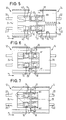
- FIG. 5 shows a schematic, partially sectioned top view of the two Housing modules 24, 26 before plugging the two connector parts together 12, 14.
- the adapter 28 is through the compression spring 34 loaded into its left pre-assembly position, in which the projections 32 rest on the left edge of the slots 30.
- the housed in the housing module 24 Ferrules 16 are not yet locked in place with the adapter 28.
- FIG. 6 shows a schematic, partially sectioned representation of the two housing modules 24, 26, the two connector parts 12, 14 already are plugged together so far that the ferrules 16 with the Adapters 28 are locked. The locking of the ferrules 16, 18 with the Adapter 28 thus takes place laterally before mutual locking of the two connector parts 12, 14.
- Figure 7 shows a schematic, partially sectioned top view of the two Housing modules 24, 26, the two connector parts 12, 14 completely plugged together and the two housing modules 24, 26 merged are or with their mutually facing end faces adjoin. In this case, it takes the adapter 28 and the this latched ferrules 16, 18 comprising an optical unit retracted Operating position in which they are when plugging the two connector parts 12, 14 moves against the force of the compression spring 34 has been.
Landscapes
- Physics & Mathematics (AREA)
- General Physics & Mathematics (AREA)
- Optics & Photonics (AREA)
- Mechanical Coupling Of Light Guides (AREA)
Abstract
Description
Der Adapter kann für ein oder auch mehrere Ferrulepaare vorgesehen sein. So ist beispielsweise auch die Verwendung eines gemeinsamen Adapters für insbesondere zwei Ferrulepaare denkbar.
- Figur 1
- eine schematische, perspektivische Ansicht zweier zusammengeführter, jeweils zwei Ferrulen aufnehmender Gehäusemodule, die in die beiden Verbinderteile eines Steckverbinders einsetzbar sind,
- Figur 2
- die in das jeweilige Verbinderteil des Steckverbinders eingesetzten Gehäusemodule,
- Figur 3
- einen Horizontalschnitt durch die beiden zusammengeführten Gehäusemodule,
- Figur 4
- einen Vertikalschnitt durch die beiden zusammengeführten Gehäusemodule,
- Figur 5
- eine schematische, teilweise geschnittene Draufsicht der beiden Gehäusemodule vor dem Zusammenstecken der beiden Verbinderteile,
- Figur 6
- eine schematische, teilweise geschnittene Draufsicht der beiden Gehäusemodule, wobei die beiden Verbinderteile bereits so weit zusammengesteckt sind, daß die Ferrulen über den Adapter miteinander verriegelt sind, und
- Figur 7
- eine schematische, teilweise geschnittene Draufsicht der beiden Gehäusemodule, wobei die beiden Verbinderteile vollständig zusammengesteckt und die beiden Gehäusemodule zusammengeführt sind.
- 10
- Steckverbinder
- 12
- Verbinderteil
- 14
- Verbinderteil
- 16
- Ferrule
- 18
- Ferrule
- 20
- Lichtleiter
- 22
- Lichtleiter
- 24
- Gehäusemodul
- 26
- Gehäusemodul
- 28
- optischer Adapter
- 30
- Schlitz
- 32
- Vorsprung
- 34
- Druckfeder
- 36
- axialer Ansatz
- 38
- Anschlagsfläche
- 40
- Verriegelungsarm
- 42
- Verriegelungsfläche
- 44
- Rastarm
- 46
- Ausrichtabschnitt
- 48
- axiale Ausrichtöffnung
- 50
- axialer Ansatz
- 52
- Stirnfläche
- 54
- Anschlagfläche
- x
- Steck- oder Axialrichtung
Claims (19)
- Steckverbinder (10) mit zwei zusammensteckbaren Verbinderteilen (12, 14), die jeweils mit wenigstens einer optischen Ferrule (16, 18) versehen sind, die bei zusammengesteckten Verbinderteilen (12, 14) einer dem anderen Verbinderteil (14, 12) zugeordneten optischen Ferrule (18, 16) gegenüberliegt, um eine jeweilige Lichtleiterverbindung herzustellen,
dadurch gekennzeichnet,
daß die den beiden Verbinderteilen (12, 14) zugeordneten optischen Ferrulen (16, 18) jeweils in einem Gehäusemodul (24, 26) untergebracht sind, das bei zusammengesteckten Verbinderteilen (12, 14) einem dem anderen Verbinderteil (14, 12) zugeordneten Gehäusemodul (26, 24) gegenüberliegt, daß eines (24) der beiden Gehäusemodule (24, 26) mit einem optischen Adapter (28) versehen ist, über den die beiden einander gegenüberliegenden Ferrulen (16, 18) miteinander verriegelbar sind, daß der Adapter (28) in Steck- oder Axialrichtung (x) relativ zum betreffenden Gehäusemodul (26) verschiebbar und federnd in eine Vormontagestellung belastet ist und daß der Adapter (28) beim Zusammenstecken der beiden Verbinderteile (12, 14) zusammen mit den mit ihm verrasteten und entsprechend an ihm fixierten Ferrulen (16, 18) entgegen der Federkraft in eine Betriebsstellung bewegbar ist. - Steckverbinder nach Anspruch 1,
dadurch gekennzeichnet,
daß die Verriegelung der Ferrulen (16, 18) mit dem Adapter (28) im Verlauf des Zusammensteckens der beiden Verbinderteile zeitlich vor einer gegenseitigen Verriegelung der beiden Verbinderteile (12, 14) erfolgt. - Steckverbinder nach Anspruch 1 oder 2,
dadurch gekennzeichnet,
daß die gegenseitige Ausrichtung der Ferrulen (16, 18) über die Gehäusemodule (24, 26) erfolgt. - Steckverbinder nach einem der vorhergehenden Ansprüche,
dadurch gekennzeichnet,
daß der Adapter (28) wenigstens zwei einander gegenüberliegende federnde Verriegelungselemente (40) umfaßt, die mit einer an einer jeweiligen Ferrule (16, 18) vorgesehenen Verriegelungsfläche (42) in Eingriff bringbar sind. - Steckverbinder nach Anspruch 4,
dadurch gekennzeichnet,
daß die federnden Verriegelungselemente jeweils durch einen federnden Verriegelungsarm (40) gebildet sind. - Steckverbinder nach Anspruch 4 oder 5,
dadurch gekennzeichnet,
daß die Verriegelungsfläche (42) durch eine an der Ferrule (16, 18) vorgesehene Nut gebildet ist. - Steckverbinder nach Anspruch 6,
dadurch gekennzeichnet,
daß die Nut (42) durch eine Umfangsnut gebildet ist. - Steckverbinder nach einem der vorhergehenden Ansprüche,
dadurch gekennzeichnet,
.daß die über den Adapter (28) erfolgende Verriegelung der Ferrulen (16, 18) auch bei seine Betriebsstellung einnehmendem Adapter (28) aufrechterhalten ist. - Steckverbinder nach einem der vorhergehenden Ansprüche,
dadurch gekennzeichnet,
daß die federnden Verriegelungselemente (40) zumindest bei zusammengesteckten Verbinderteilen (12, 14) und entsprechend zusammengeführten Gehäusemodulen (24, 26) durch Zweitverriegelungsmittel mit der Verriegelungsfläche (42) in Eingriff gehalten sind. - Steckverbinder nach einem der vorhergehenden Ansprüche,
dadurch gekennzeichnet,
daß die im den Adapter (28) aufweisenden Gehäusemodul (26) untergebrachte Ferrule (18) durch federnde Verriegelungselemente (40) mit dem Adapter (28) verriegelt und diese Verriegelung bei in das betreffende Verbinderteil (14) eingesetztem Gehäusemodul (26) durch Zweitverriegelungsmittel gesichert ist. - Steckverbinder nach Anspruch 10,
dadurch gekennzeichnet,
daß die Verriegelungselemente (40) bei in das betreffende Verbinderteil (14) eingesetztem Gehäusemodul (26) durch die Innenwand des Verbinderteils (14) mit der an der Ferrule (18) vorgesehenen Verriegelungsfläche (42) in Eingriff gehalten sind. - Steckverbinder nach einem der vorhergehenden Ansprüche,
dadurch gekennzeichnet,
daß die Gehäusemodule (24, 26) jeweils mit dem betreffenden Verbinderteil (12, 14) verriegelbar sind. - Steckverbinder nach einem der vorhergehenden Ansprüche,
dadurch gekennzeichnet,
daß der Adapter (28) durch wenigstens ein in dem betreffenden Gehäusemodul (26) untergebrachtes Federelement (34) in die Vormontagestellung belastet ist. - Steckverbinder nach einem der vorhergehenden Ansprüche,
dadurch gekennzeichnet,
daß das Federelement eine am Gehäusemodul (26) abgestützte Druckfeder (34) umfaßt. - Steckverbinder nach einem der vorhergehenden Ansprüche,
dadurch gekennzeichnet,
daß der Adapter (28) wenigstens einen Ausrichtabschnitt (46) umfaßt, der eine durchgehende axiale Ausrichtöffnung (48) besitzt, in die axiale Ansätze (50) der Ferrulen (16, 18) einsteckbar sind, und an seinen beiden Enden Stirnflächen (52) aufweist, die mit an den Ferrulen (16, 18) vorgesehenen Anschlagflächen (54) zusammenwirken und an denen die mit dem Adapter (28) verriegelten Ferrulen (16, 18) anliegen. - Steckverbinder nach einem der vorhergehenden Ansprüche,
dadurch gekennzeichnet,
daß in einem jeweiligen Gehäusemodul (24, 26) jeweils wenigstens ein Ferrule (16, 18) untergebracht ist. - Steckverbinder nach einem der vorhergehenden Ansprüche,
dadurch gekennzeichnet,
daß in einem jeweiligen Gehäusemodul (24, 26) jeweils wenigstens zwei Ferrulen (16, 18) untergebracht sind. - Steckverbinder nach einem der vorhergehenden Ansprüche,
dadurch gekennzeichnet,
daß der Adapter (28) für wenigstens ein Ferrulepaar (16, 18) vorgesehen ist. - Steckverbinder nach einem der vorhergehenden Ansprüche,
dadurch gekennzeichnet,
daß für wenigstens zwei Ferrulepaare (16, 18) ein gemeinsamer Adapter (28) vorgesehen ist.
Applications Claiming Priority (2)
| Application Number | Priority Date | Filing Date | Title |
|---|---|---|---|
| DE10004603 | 2000-02-03 | ||
| DE2000104603 DE10004603A1 (de) | 2000-02-03 | 2000-02-03 | Steckverbinder |
Publications (1)
| Publication Number | Publication Date |
|---|---|
| EP1122563A1 true EP1122563A1 (de) | 2001-08-08 |
Family
ID=7629616
Family Applications (1)
| Application Number | Title | Priority Date | Filing Date |
|---|---|---|---|
| EP01101086A Withdrawn EP1122563A1 (de) | 2000-02-03 | 2001-01-18 | Steckverbinder |
Country Status (2)
| Country | Link |
|---|---|
| EP (1) | EP1122563A1 (de) |
| DE (1) | DE10004603A1 (de) |
Citations (1)
| Publication number | Priority date | Publication date | Assignee | Title |
|---|---|---|---|---|
| US5940561A (en) * | 1997-04-23 | 1999-08-17 | Siecor Corporation | Adapter assembly for precise alignment of fiber optic connectors |
Family Cites Families (3)
| Publication number | Priority date | Publication date | Assignee | Title |
|---|---|---|---|---|
| DE9320829U1 (de) * | 1992-11-26 | 1995-03-02 | Diamond S.A., Losone, Locarno | Steckverbindung für Lichtwellenleiter |
| GB9307488D0 (en) * | 1993-04-08 | 1993-06-02 | Amp Holland | Optical fibre connector latching mechanism |
| US5993071A (en) * | 1996-09-30 | 1999-11-30 | The Whitaker Corporation | Apparatus for connecting optical fibre connectors |
-
2000
- 2000-02-03 DE DE2000104603 patent/DE10004603A1/de not_active Withdrawn
-
2001
- 2001-01-18 EP EP01101086A patent/EP1122563A1/de not_active Withdrawn
Patent Citations (1)
| Publication number | Priority date | Publication date | Assignee | Title |
|---|---|---|---|---|
| US5940561A (en) * | 1997-04-23 | 1999-08-17 | Siecor Corporation | Adapter assembly for precise alignment of fiber optic connectors |
Also Published As
| Publication number | Publication date |
|---|---|
| DE10004603A1 (de) | 2001-08-09 |
Similar Documents
| Publication | Publication Date | Title |
|---|---|---|
| EP1102098B1 (de) | Steckverbinder für Lichtleiter | |
| EP1775612B1 (de) | Optische Kabelanschlussvorrichtung | |
| DE69432625T2 (de) | Faseroptische verbindungsanordnung | |
| EP1006378B1 (de) | Steckverbindung mit einer Mehrzahl von parallel angeordneten Lichtwellenleitern | |
| EP1151338B1 (de) | Optischer steckverbinder | |
| EP2962142B1 (de) | Optisches modul für modular aufgebaute industriesteckverbinder | |
| DE2622607C3 (de) | Selbstzentrierende Steckverbindungsanordnung für Lichtwellenleiter | |
| EP0805366A1 (de) | Steckverbindung | |
| DE3517388A1 (de) | Anschlussteil fuer ein faser-optisches kabel | |
| EP1792217A1 (de) | Innengehäuse für einen lichtwellenleiter-steckverbinder | |
| DE19516241A1 (de) | Lichtwellenleiterverbinder | |
| EP1247125A2 (de) | Mehrkanalige optische koppelanordnung | |
| EP0762164A2 (de) | Befestigungsvorrichtung für Lichtwellenleiter | |
| WO1994011767A1 (de) | Stecker für eine steckverbindung von lichtwellenleitern | |
| DE19539549C1 (de) | Optischer Steckverbinder | |
| DE29607793U1 (de) | Steckverbindung | |
| DE10004603A1 (de) | Steckverbinder | |
| EP1052531A1 (de) | Steckverbinder | |
| EP1146369A2 (de) | Steckverbinder für Lichtleiter | |
| DE10061272B4 (de) | Lichtleiter-Steckverbinder | |
| EP1674907B1 (de) | Stecker für Lichtwellenleiter | |
| DE3327575A1 (de) | Steckverbinder fuer lichtwellenleiter | |
| EP1065541A1 (de) | Steckverbinder | |
| EP1037079A2 (de) | Steckverbinder für Lichtleiter | |
| DE10200850A1 (de) | Baugruppe bestehend aus elektronischem Bauteil und Werkzeug zum Austauschen des Bauteils sowie Verfahren zum Austauschen eines elektronischen Bauteils |
Legal Events
| Date | Code | Title | Description |
|---|---|---|---|
| PUAI | Public reference made under article 153(3) epc to a published international application that has entered the european phase |
Free format text: ORIGINAL CODE: 0009012 |
|
| AK | Designated contracting states |
Kind code of ref document: A1 Designated state(s): DE FR IT |
|
| AX | Request for extension of the european patent |
Free format text: AL;LT;LV;MK;RO;SI |
|
| 17P | Request for examination filed |
Effective date: 20011002 |
|
| AKX | Designation fees paid |
Free format text: DE FR IT |
|
| RTI1 | Title (correction) |
Free format text: OPTICAL CONNECTOR |
|
| GRAP | Despatch of communication of intention to grant a patent |
Free format text: ORIGINAL CODE: EPIDOSNIGR1 |
|
| STAA | Information on the status of an ep patent application or granted ep patent |
Free format text: STATUS: THE APPLICATION IS DEEMED TO BE WITHDRAWN |
|
| 18D | Application deemed to be withdrawn |
Effective date: 20070626 |