EP1122477A2 - Pipe fastener - Google Patents
Pipe fastener Download PDFInfo
- Publication number
- EP1122477A2 EP1122477A2 EP01300925A EP01300925A EP1122477A2 EP 1122477 A2 EP1122477 A2 EP 1122477A2 EP 01300925 A EP01300925 A EP 01300925A EP 01300925 A EP01300925 A EP 01300925A EP 1122477 A2 EP1122477 A2 EP 1122477A2
- Authority
- EP
- European Patent Office
- Prior art keywords
- pipe
- stud
- body panel
- electrical connection
- connection member
- Prior art date
- Legal status (The legal status is an assumption and is not a legal conclusion. Google has not performed a legal analysis and makes no representation as to the accuracy of the status listed.)
- Granted
Links
- 239000000446 fuel Substances 0.000 claims abstract description 20
- 239000000463 material Substances 0.000 claims abstract description 19
- 239000004020 conductor Substances 0.000 claims abstract description 14
- 239000004033 plastic Substances 0.000 claims abstract description 7
- 229920003023 plastic Polymers 0.000 claims abstract description 7
- 229930182556 Polyacetal Natural products 0.000 claims description 10
- 229920006324 polyoxymethylene Polymers 0.000 claims description 10
- 239000011347 resin Substances 0.000 claims description 9
- 229920005989 resin Polymers 0.000 claims description 9
- 239000004677 Nylon Substances 0.000 description 2
- 239000004743 Polypropylene Substances 0.000 description 2
- 230000008878 coupling Effects 0.000 description 2
- 238000010168 coupling process Methods 0.000 description 2
- 238000005859 coupling reaction Methods 0.000 description 2
- 229920002457 flexible plastic Polymers 0.000 description 2
- 239000002184 metal Substances 0.000 description 2
- 229920001778 nylon Polymers 0.000 description 2
- -1 polypropylene Polymers 0.000 description 2
- 229920001155 polypropylene Polymers 0.000 description 2
- 239000000853 adhesive Substances 0.000 description 1
- 230000001070 adhesive effect Effects 0.000 description 1
- 239000011248 coating agent Substances 0.000 description 1
- 238000000576 coating method Methods 0.000 description 1
Images

Classifications
-
- F—MECHANICAL ENGINEERING; LIGHTING; HEATING; WEAPONS; BLASTING
- F16—ENGINEERING ELEMENTS AND UNITS; GENERAL MEASURES FOR PRODUCING AND MAINTAINING EFFECTIVE FUNCTIONING OF MACHINES OR INSTALLATIONS; THERMAL INSULATION IN GENERAL
- F16L—PIPES; JOINTS OR FITTINGS FOR PIPES; SUPPORTS FOR PIPES, CABLES OR PROTECTIVE TUBING; MEANS FOR THERMAL INSULATION IN GENERAL
- F16L3/00—Supports for pipes, cables or protective tubing, e.g. hangers, holders, clamps, cleats, clips, brackets
- F16L3/22—Supports for pipes, cables or protective tubing, e.g. hangers, holders, clamps, cleats, clips, brackets specially adapted for supporting a number of parallel pipes at intervals
- F16L3/223—Supports for pipes, cables or protective tubing, e.g. hangers, holders, clamps, cleats, clips, brackets specially adapted for supporting a number of parallel pipes at intervals each support having one transverse base for supporting the pipes
Definitions
- the present invention relates to a pipe fastener for securing pipes used to supply fuel, brake oil or the like in an automobile, to a body panel such as a body of the automobile.
- Japanese Utility Model Laid-open No. 04-058683 has suggested using a support member made of electrical conducting resin to support the pipe to discharge the electric charge on the pipe to a body panel.
- this support member must be made of such flexible material as polypropylene containing the electrical conducting material mixed therein so as to be conductive as a whole. Accordingly, the flexibility of the support member disadvantageously makes it difficult to increase an ability to hold the pipe.
- the pipe fastener illustrated in Fig. 3 of Japanese Utility Model Laid-open No. 04-058683 mentioned above the pipe tends to be detached from the fastener under the bumpy condition in an automobile, and it requires a complicated mounting operation, such as entirely surrounding the pipe, as shown in Figs. 1 and 2 thereof.
- an object of the present invention is to provide a pipe fastener which allows a pipe to be mounted to a body panel by an easy operation and also provides sufficient holding force, while electric charge on a charged pipe can be discharged to the body panel.
- a pipe fastener for fastening a pipe such as a fuel pipe to a body panel of a vehicle by engaging with a stud fixedly connected to the body panel, comprising: a pipe holder of rigid plastic material including a base having a stud receiving hole formed therein and a pipe grip integrally molded with the base for holding the pipe by pressing the pipe into an opening of the grip, the stud receiving hole having an engagement pawl formed therein for engagement with a received stud to be secured; and an electrical connection member of electrical conducting material adapted to be attached to the pipe holder by an engagement means formed in the pipe holder; and wherein the electrical connecting member includes a pipe contact portion extending to the pipe grip into contact with the pipe held in the pipe grip when the electrical connection member is attached to the pipe holder by the engagement means; and a stud contact portion adapted to contact with the stud received in the stud receiving hole, so that the pipe in contact with the pipe contact portion is electrically connected to the body panel through the
- the pipe fastener which is made of material having sufficient strength and provides an easy mounting operation and sufficient holding force, while allowing the electric charges which are accumulated on the pipe, to be discharged to the body panel through the electrical connection member, thus to solve the problem accompanied with the accumulated electric charges on the pipe.
- the pipe contact portion of the electrical connection member may be made to have a pipe receiving surface extending from the surface opposite to the opening side of the pipe grip to the opening of the pipe grip, and the stud contact portion of the electrical connection member may be made to have a stud engagement hole adapted to be aligned to engage with the side of the stud which projects from the stud receiving hole.
- the engagement means can be an engagement leg standing on a surface opposite to the opening of the pipe grip, and the electrical connection member may be provided with an engagement hole to receive the engagement leg into engagement therewith, so that the electrical connection member is attached to the pipe holder by aligning the engagement hole of the electrical engagement member with the engagement leg and pressing the member to the leg.
- the pipe holder may be made of tough and flexible resin such as polyacetal, and the electrical connection member is made of resin such as electrical conducting material mixed polyacetal resin.
- the pipe contacting the pipe contact portion may be a fuel pipe.
- the electrical connection member may be removably attached to the pipe holder.
- the present invention provides an alternative pipe fastener for fastening a pipe such as a fuel pipe to a body panel, comprising: a pipe holder of rigid plastic material including a base to be secured to the body panel and a pipe grip integrally molded with the base for holding the pipe by pressing the pipe into an opening of the grip; and an electrical connection member of electrical conducting material adapted to be attached to the pipe holder by an engagement means formed in the pipe holder; and wherein the electrical connecting member includes a pipe contact portion extending to the pipe grip into contact with the pipe held in the pipe grip when the electrical connection member is attached to the pipe holder by the engagement means; and a body panel contact portion extending from the pipe holder fixed to the body panel to a direct contact position where the body panel contact portion comes in direct contact with the body panel, so that the pipe in contact with the pipe contact portion is directly electrically connected to the body panel.
- the pipe fastener which is made of material having sufficient strength and provides an easy mounting operation and sufficient holding force, while allowing the electric charges which are accumulated on the pipe, to be discharged to the body panel through the electrical connection member, thus to solve the problem accompanied with the accumulated electric charges.
- the body panel contact portion may be made to have a brim portion adapted to be clamped between said body panel and said base secured to said body panel.
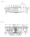
- a pipe fastener 1 comprises a pipe holder 2 and an electrical connection member 3.
- the pipe holder 2 is made of, for example, integrally molded single-piece of rigid plastic material such as polyacetal to obtain sufficient strength for holding a pipe.
- the electrical connection member 3 is made of electrical conducting material.
- the electrical connection member 3 may be made of any material so far as it is conductive as a whole, including rigid material such as conducting metal, flexible material such as conducting rubber, and even somehow brittle material such as polyacetal resin mixed with electrical conducting material.
- the electrical connection member 3 is assembled with the pipe holder to make the pipe fastener 1.
- the pipe holder 2 of the pipe fastener 1 comprises a base 9 having a stud receiving hole 7 formed therein for receiving a stud 6 fixedly connected to a body panel 5, and a pipe gripping portion 10 integrally molded with the base 9 extending therefrom in the lateral direction for holding pipes by pressing the pipes into opening portions formed thereon.
- the pipe gripping portion 10 is formed on each of the left and right sides of the base 9 for holding many pipes.
- the pipe gripping portion 10 has desired number of pipe grips 11-15 on demand, each of which is formed in a U-shaped groove with its top portion opening upward.
- each pipe grip has a resilient wing 17 formed therein extending diagonally from an upper end of the pipe grip toward the bottom surface of the groove to prevent the pipes 19-23 pressed thereinto from being detached therefrom.
- a resilient wing 17 formed therein extending diagonally from an upper end of the pipe grip toward the bottom surface of the groove to prevent the pipes 19-23 pressed thereinto from being detached therefrom.
- two resilient wings may be arranged for each pipe grip 14 or 15.
- each pipe gripping portion 10 has an engagement leg 25 as an engagement means, vertically arranged on a surface in an opposite side to the opening portion of the respective pipe grips to securely engage with the electrical connection member 3.
- Two engagement legs 25 are preferably arranged, as illustrated, to ensure that the electrical connection member 3 is coupled with the pipe holder. However, one or more than two engagement legs 25 may be provided so far as such coupling is ensured.
- the tip of the respective engagement leg is provided with a resilient pawl 26 for easy attachment of the electrical connection member 3 and for higher coupling force after the attachment.
- the resilient pawl 26, as shown in Fig. 3, is designed to be pressed by a finger or the like to be disengaged from the electrical connection member. That is, the electrical connection member is detachably attached to the pipe holder. Accordingly, if no pipe needs grounding, the electrical connection member 3 can be detached from the pipe fastener 1, leaving the pipe holder 2 to be solely used.
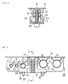
- the stud receiving hole 7 of the base 9 is formed as an elongated hole parallel to a longitudinal direction (the vertical direction in Fig. 2) of the pipe held in the pipe gripping portion 10 to absorb a space or pitch error between a plurality of studs standing on the body panel 5.
- the stud receiving hole 7 has two pairs of engagement pawls 27 formed therein for engaging with a thread portion of the received stud.
- Each engagement pawl 27 is composed of a plate-like piece extending in parallel with the longitudinal direction of the stud receiving hole 7, and the plate-like pieces are located opposite to each other in a pair placing the stud receiving space therebetween.
- Each one of the engagement pawls 27 is located to be staggered along a height direction (the vertical direction in Fig. 3) so as to meet with a thread pitch of the stud 6.
- the each engagement pawl 27 may preferably be formed in crotch shape, as illustrated, to increase an area to engage with the stud.
- the electrical connection member 3 will now be described in detail with reference to Figs. 1 to 4.
- the electrical connection member 3 is coupled with and held by the pipe holder 2 using the engagement leg 25 located on a bottom surface (the under surface in Fig. 1) of the pipe holder 2 to be, in its coupled configuration, formed into the pipe fastener 1.
- the electrical connection member 3, as held by the pipe holder 2 comprises pipe contact portions 29 which extend toward the pipe grip 13 or the like to comes into contact with a pipe 21 held in the pipe grip 13, and a stud contact portion 30 which comes into contact with the stud 6 in the stud receiving hole 7.
- the stud contact portion 30 is made as a plate to be a base of the electrical connection member 3 and has a stud engagement hole 31 formed in a center thereof through which the stud penetrates while keeping contact therewith.
- the stud engagement hole 31 is formed to be an elongated hole so as to meet with the elongated hole of the stud receiving hole 7 to absorb the pitch error between a plurality of studs.
- Two inner walls facing opposite to each other in the longer edge sides of the stud engagement hole 31 are the stud contact walls to firmly engage with the stud.
- a distance between two inner walls is made to be equal to or smaller than an outer diameter of the stud, so that when the stud passes through the stud engagement hole 31, the thread portion of the stud makes inroad into the inner walls of the longer edge sides of the stud engagement hole 31 to ensure that the stud contact portion 30 is brought into contact with the stud 6.
- the pipe contact portions 29 extend along the pipe holder 2 from the opposite surface to the opening of the pipe grip (e.g. pipe grip 13) or the bottom surface toward the opening portion of the pipe grip of the pipe holder 2. More specifically, each of the pipe contact portion 29 is formed so as to be raised from a side edge of the plate-like stud contact portion 30 toward the pipe grip (e.g. pipe grip 13) and its upper portion is formed to be a pipe receiving surface 33 in a circular concave shape to receive and contact the outer surface of the fuel pipe 21 held in the pipe grip 13.
- the pipe contact portion 29, as illustrated, is preferably formed on both edge portions located in the opposite sides of the stud contact portion 30 respectively so as to make the contacting area larger as well as to increase the strength of the stud contact portion and eventually to increase the strength of the electrical connection member 3.
- an upright wall portion 34 having a height lower than that of the pipe contact portion 29 is preferably formed continuous with each pipe contacting portion 29 on each edge portion of the stud contact portion 30.
- the distance between the pair of pipe contact portions 29 and the upright walls 34 i.e. a width of the stud contact portion 30
- the pipe contact portion 29 and the upright wall 34 can be formed as a guide upon combining the electrical connection member 3 with the pipe holder 2, which facilitate the assembling operation. Bringing the distance between the pair of pipe contact portions 29 and the upright walls 34 closer to the width of the bottom surface of the pipe holder makes the assembling to be more stable without looseness or clattering.
- the stud contact portion 30, which is the base of the electrical connection member 3, is provided with an engagement hole 35 for receiving the engagement leg 25 of the pipe holder 2 to engage with the resilient pawl 26. A shape, location, and number of the engagement hole 35 are respectively determined to suit the engagement leg 25 of the pipe holder 2.
- Each engagement hole 35 has an edge portion with which the resilient pawl 26 engages after each engagement leg 25 is completely inserted through the corresponding engagement hole 35 (see Fig. 3), so that the electrical connection member 3 is easily but also securely coupled to the bottom surface of the pipe holder 2 to be formed into the pipe fastener 1.
- Figs. 2 to 4 show the pipe fastener 1 in its coupled condition. Under such coupled condition, the pipe fastener 1 can be for sales or for delivering to users to be used.
- the electrical connection member 3 may be made of any desired electrical conducting material.
- the electrical connection member may be made of, for example, less rigid material such as conducting rubber, polypropylene mixed with electrical conducting material or the like, or contrarily more rigid conducting metal, or further, brittle material such as polyacetal mixed with electrical conducting material.
- the pipe 21 with which the receiving surface 33 of the pipe contact portion 29 comes into contact is a fuel pipe.
- the pipe contact portion 29 may be designed to come into contact with a pipe other than a fuel pipe, for example, brake oil pipe or the like.
- the number of pipes in contacting therewith may be two or more in accordance with the number of the pipes which need grounding.
- the number of the pipe contact sections 29 and the shape of the pipe receiving surface 33 may also be arbitrarily defined corresponding to the number and the shape of the pipes to be contacted.
- Fig. 3 shows the pipes 19-23 mounted to the body panel 5 using the pipe fastener 1 configured as described above.
- the pipe holder 1 is located in a predetermined position in relation to the pipes 19-23, and then the pipes 19-23 are pressed into the corresponding pipe grips 12-15 of the pipe gripping portion 10 respectively so as to be held therein.
- a plurality of pipe holders 1 are attached to the pipe(s) with predetermined positions and intervals therebetween, and then, the pipe(s) having the pipe holders assembled thereto are supplied to the body panel 5 on which a plurality of studs are fixed with predetermined positions and intervals thereon, and then, each pipe holder 1 is pressed to the stud 6 so as to receive into the corresponding stud receiving hole 7.
- the engagement pawl 27 engages with the stud bolt 6 and the pipe holder 1 is mounted to the body panel 5, and thus the pipes 19-23 are fastened to the body panel 5.
- the electrical connection member 3 is, on its pipe receiving surface 33 of the pipe contact portion 29, brought into contact with the outer surface of the pipe 21 to establish electrical connection therebetween.
- the inner wall of the stud engagement hole 31 of the stud contact portion 30 also comes into contact with the thread of the stud 6 to bring the electrical connection member 3 into electrically connected to the stud 6. Since the electrical connection member 3 is conductive, the pipe 21 which is in contact with the pipe contact portion 29 is electrically connected to the body panel 5 via the stud 6.
- a bold solid line 37 represents the electrical connection line. That is, the electrical connection member 3 works to ground the pipe to the body panel. It should be noted that since a function of holding a pipe relies on the pipe holder 2, the electrical member 3 should not necessarily be rigid, but of course, could be rigid.
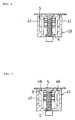
- Figs. 5 and 6 show a pipe fastener 38 according to a second embodiment of the present invention.
- an electrical connection member 39 does not have a stud contact portion but has a body panel contact portion 41 extending to a position where it comes into direct contact with the body panel. Since the rest of parts of the pipe fastener 38 are similar to those of the pipe fastener 1 according to the first embodiment shown in Figs. 1 to 4, the detailed description will be omitted.
- the body panel contact portion 41 has a body panel contact surface formed in an upper portion thereof, and pressing the pipe fastener 1 toward a body panel 5 brings the body panel contact portion 41 into contact with the body panel 5 to establish the electrical connection between the electrical connection member 39 and the body panel 5.
- the electrical connection member 39 is electrically connected to the pipe 21. Accordingly, the electrical connection member 39 (thus the pipe fastener 38), because of its holding the pipe 21 therein, can electrically connect the pipe 21 directly to the body panel and discharge the electric charges on the pipe 21 to the body panel 5.
- the electrical connection line thereof is indicated by a bold solid line 42 in Fig 5. It should be noted that, in this embodiment, since the pipe can be grounded to the body panel without passing through the stud 6, the pipe fastener 1 may be of such type that could be mounted to the body panel without using stud.
- the pipe fastener 1 may be formed to have a anchor type engagement pawl which is inserted into a mounting hole of the body panel to be securely coupled to the body panel, or the pipe fastener 1 may be fixedly connected to the body panel by any means, for example, using bolt and nut, adhesives or the like.
- Fig. 7 shows a pipe fastener 43 according to a third embodiment of the present invention.
- the pipe fastener 43 is almost same as the pipe fastener 38 according to the second embodiment, excepting that a body panel contact portion 45 of its electrical connection member additionally has a brim portion 46 clamped between the body panel 5 and the base 9 of the pipe fastener secured onto the body panel 5.
- the brim portion 46 By providing the brim portion 46, the body panel contact portion 45 is in more securely contact with the body panel 5 with larger contacting area, and the electric resistance becomes much lower than that in the second embodiment which makes the electrical connection between the electrical connection member and the body panel, and therefore, the electrical connection can be more securely established therebetween.
- a pipe holder can be made of material having sufficient strength so as to allow easy mounting operation and to provide sufficient holding force, while electric charges accumulated on a pipe can be discharged to a body panel by an electrical connection means, so that a problem accompanied by the charges to be accumulated on the pipe can be dissolved, and further, the pipe can be attached to the body panel with easy mounting operation while keeping a sufficient holding force.
Landscapes
- Engineering & Computer Science (AREA)
- General Engineering & Computer Science (AREA)
- Mechanical Engineering (AREA)
- Supports For Pipes And Cables (AREA)
- Dowels (AREA)
Abstract
Description
Claims (8)
- A pipe fastener for fastening a pipe such as a fuel pipe to a body panel of a vehicle by engaging with a stud fixedly connected to said body panel, comprising:a pipe holder of rigid plastic material including a base having a stud receiving hole formed therein and a pipe grip integrally molded with said base for holding said pipe by pressing said pipe into an opening of said grip, said stud receiving hole having an engagement pawl formed therein for engagement with a received stud to be secured; andan electrical connection member of electrical conducting material adapted to be attached to said pipe holder by an engagement means formed in said pipe holder;wherein said electrical connecting member includes a pipe contact portion extending to said pipe grip into contact with said pipe held in said pipe grip when said electrical connection member is attached to said pipe holder by said engagement means; and a stud contact portion adapted to contact with said stud received in said stud receiving hole, so that said pipe in contact with said pipe contact portion is electrically connected to said body panel through said stud.
- A pipe fastener in accordance with claim 1, in which said pipe contact portion of said electrical connection member has a pipe receiving surface extending from the surface opposite to the opening side of said pipe grip to said opening of said pipe grip, and said stud contact portion of said electrical connection member has a stud engagement hole adapted to be aligned to engage with the side of said stud which projects from said stud receiving hole.
- A pipe fastener in accordance with claim 2, in which said engagement means is an engagement leg standing on a surface opposite to said opening of said pipe grip, and said electrical connection member is provided with an engagement hole to receive said engagement leg into engagement therewith, so that said electrical connection member is attached to said pipe holder by aligning said engagement hole of said electrical engagement member with said engagement leg and pressing said member to the leg.
- A pipe fastener for fastening a pipe such as a fuel pipe to a body panel of a vehicle, comprising;a pipe holder of rigid plastic material including a base to be secured to said body panel and a pipe grip integrally molded with said base for holding said pipe by pressing said pipe into an opening of said grip; andan electrical connection member of electrical conducting material adapted to be attached to said pipe holder by an engagement means formed in said pipe holder;wherein said electrical connecting member includes a pipe contact portion extending to said pipe grip into contact with said pipe held in said pipe grip when said electrical connection member is attached to said pipe holder by said engagement means; and a body panel contact portion extending from said pipe holder fixed to said body panel to a direct contact position where said body panel contact portion comes in direct contact with said body panel, so that said pipe in contact with said pipe contact portion is directly electrically connected to said body panel.
- A pipe fastener in accordance with claim 4, in which said body panel contact portion has a brim portion adapted to be clamped between said body panel and said base secured to said body panel.
- A pipe fastener in accordance with either of claims 1 to 5, in which said pipe holder is made of tough and flexible resin such as polyacetal, and said electrical connection member is made of resin such as electrical conducting material mixed polyacetal resin.
- A pipe fastener in accordance with either of claims 1 to 6, in which said pipe contacting said pipe contact portion is a fuel pipe.
- A pipe fastener in accordance with either of claim 1 to 7, in which said electrical connection member is removably attached to said pipe holder.
Applications Claiming Priority (2)
| Application Number | Priority Date | Filing Date | Title |
|---|---|---|---|
| JP2000023629 | 2000-02-01 | ||
| JP2000023629A JP2001214988A (en) | 2000-02-01 | 2000-02-01 | Pipe fixture |
Publications (3)
| Publication Number | Publication Date |
|---|---|
| EP1122477A2 true EP1122477A2 (en) | 2001-08-08 |
| EP1122477A3 EP1122477A3 (en) | 2003-06-04 |
| EP1122477B1 EP1122477B1 (en) | 2004-07-28 |
Family
ID=18549755
Family Applications (1)
| Application Number | Title | Priority Date | Filing Date |
|---|---|---|---|
| EP01300925A Expired - Lifetime EP1122477B1 (en) | 2000-02-01 | 2001-02-01 | Pipe fastener |
Country Status (6)
| Country | Link |
|---|---|
| US (1) | US6450459B2 (en) |
| EP (1) | EP1122477B1 (en) |
| JP (1) | JP2001214988A (en) |
| AT (1) | ATE272184T1 (en) |
| DE (1) | DE60104456T2 (en) |
| ES (1) | ES2225420T3 (en) |
Cited By (7)
| Publication number | Priority date | Publication date | Assignee | Title |
|---|---|---|---|---|
| GB2372488B (en) * | 2001-02-26 | 2004-03-17 | Honda Motor Co Ltd | Antistatic structure of fuel pipe |
| GB2408635A (en) * | 2003-11-12 | 2005-06-01 | Newfrey Llc | Holder for elongate objects |
| EP1529997A3 (en) * | 2003-11-10 | 2007-05-30 | Itt Manufacturing Enterprises, Inc. | Multi-material isolator clip for supporting conduits |
| WO2013112252A1 (en) * | 2012-01-24 | 2013-08-01 | The Boeing Company | Self-indexing nut plate |
| CN103852180A (en) * | 2012-12-05 | 2014-06-11 | 海尔集团公司 | Temperature sensor fixing device and water heater |
| US8911191B2 (en) | 2012-01-24 | 2014-12-16 | The Boeing Company | Self-indexing nut plate |
| CN105680382A (en) * | 2016-04-05 | 2016-06-15 | 长葛市恒瑞电瓷电器有限公司 | Novel multi-cable fixation member |
Families Citing this family (36)
| Publication number | Priority date | Publication date | Assignee | Title |
|---|---|---|---|---|
| US7036775B2 (en) * | 2001-02-14 | 2006-05-02 | Newfrey Llc | Fastener for pipe or the like |
| US6915990B2 (en) * | 2001-05-29 | 2005-07-12 | Newfrey Llc | Pipe holding fastener |
| DE10144153A1 (en) * | 2001-09-07 | 2003-03-27 | Newfrey Llc | Clip for holding groups of pipes or cables has recesses, into which cables fit, walls between these having fingers which slope towards bases of recesses and which are offset so that they do not overlap |
| JP2003214559A (en) * | 2002-01-22 | 2003-07-30 | Nifco Inc | Clamp and fixing method of tubular material |
| US6752426B2 (en) * | 2002-04-02 | 2004-06-22 | Cf Gomma Usa, Inc. | Method of mounting a brake line to a frame or an anti-lock brakes wire |
| GB0214401D0 (en) * | 2002-06-21 | 2002-07-31 | Newell Ltd | Shelving system |
| JP2004044698A (en) * | 2002-07-12 | 2004-02-12 | Vtec Co Ltd | Clamp for long article |
| DE10306905C5 (en) * | 2003-02-18 | 2012-05-24 | Itw Automotive Products Gmbh & Co. Kg | retaining element |
| DE10306904C5 (en) * | 2003-02-18 | 2012-05-03 | Itw Automotive Products Gmbh & Co. Kg | retaining element |
| DE10340571B3 (en) * | 2003-09-01 | 2005-04-21 | Newfrey Llc, Newark | Clamp for holding flat objects |
| JP2005133826A (en) * | 2003-10-30 | 2005-05-26 | Nippon Pop Rivets & Fasteners Ltd | Pipe holder |
| JP2005133825A (en) * | 2003-10-30 | 2005-05-26 | Nippon Pop Rivets & Fasteners Ltd | Holder for tube or the like |
| ITTO20040088A1 (en) * | 2004-02-17 | 2004-05-17 | Itw Automotive Italia S R L | CLAMP RETAINING ELEMENT FOR AXIALSIMMETRIC COMPONENTS SUCH AS CABLES OR TUBES, IN PARTICULAR FOR APPLICATION ON VEHICLES |
| CA2513960A1 (en) * | 2004-07-28 | 2006-01-28 | Greenlee Textron Inc. | Device for stacking wires or cables |
| JP2006038197A (en) * | 2004-07-30 | 2006-02-09 | Nippon Pop Rivets & Fasteners Ltd | Clamp device of long size member |
| USD508394S1 (en) * | 2004-08-19 | 2005-08-16 | Greenlee Textron Inc. | Member for stacking wires or cables |
| US20060180718A1 (en) * | 2005-02-14 | 2006-08-17 | Capro, Inc. | Conduit retention clip |
| DE102005032535B4 (en) * | 2005-07-12 | 2008-03-27 | A. Raymond & Cie | Device for fastening at least one object to a carrier part provided with a fastening bolt |
| DE202006006347U1 (en) * | 2006-04-19 | 2006-06-14 | Veritas Ag | Holding device for at least one line |
| JP5206136B2 (en) * | 2008-06-10 | 2013-06-12 | マツダ株式会社 | Vehicle hose clip and vehicle hose fixing structure using the clip |
| US20090314903A1 (en) * | 2008-06-20 | 2009-12-24 | Zahuranec Terry L | Pipe clamps |
| BRPI0922695A2 (en) * | 2008-12-03 | 2017-07-11 | Alms Int Inc | SUPPORTING LIMB, SYSTEM AND METHOD FOR SUPPORTING AN Elongated LIMB |
| US9217519B2 (en) * | 2009-08-25 | 2015-12-22 | Aims International, Inc. | Systems and methods for supporting tubular members |
| US9464735B2 (en) | 2009-08-25 | 2016-10-11 | Asset Integrity Management Solutions, L.L.C. | Systems and methods for supporting tubular members |
| DE112011100629T5 (en) * | 2010-04-02 | 2014-12-11 | Illinois Tool Works Inc. | Vibration isolating vehicle mounting arrangement |
| CN102545109A (en) * | 2010-12-08 | 2012-07-04 | 鸿富锦精密工业(深圳)有限公司 | Wire arrangement device |
| US9746052B2 (en) * | 2011-02-07 | 2017-08-29 | Kevin D. Taylor | Retaining device and method of using the same |
| JP5870445B2 (en) * | 2011-11-18 | 2016-03-01 | ポップリベット・ファスナー株式会社 | Pipe fitting with earth function |
| TW201502419A (en) * | 2013-07-01 | 2015-01-16 | Tyc Brother Ind Co Ltd | LED lamp assembly and cable organization device thereof |
| US9920858B2 (en) | 2015-06-30 | 2018-03-20 | Cnh Industrial America Llc | Mounting device for tubular elements |
| USD841801S1 (en) | 2015-12-28 | 2019-02-26 | Kevin D. Taylor | Medical apparatus for retaining at least one medical device adjacent a supporting surface |
| CN110663150B (en) | 2017-06-09 | 2021-04-16 | 康普技术有限责任公司 | Supports for hangers for installing cables |
| EP3670938A1 (en) | 2018-12-21 | 2020-06-24 | A. Raymond et Cie | Toolless slot fastener |
| DE102020135045A1 (en) | 2020-12-29 | 2022-06-30 | Bombardier Transportation Gmbh | Fastening clamps for detachable attachment of cables to profile rails, system consisting of car body and fastening clamps, and assembly system |
| US12326166B2 (en) * | 2022-05-02 | 2025-06-10 | Illinois Tool Works Inc. | Combination stud and panel fastener |
| US12535094B2 (en) | 2022-06-24 | 2026-01-27 | Illinois Tool Works Inc. | Tube fastener system |
Family Cites Families (14)
| Publication number | Priority date | Publication date | Assignee | Title |
|---|---|---|---|---|
| US2227528A (en) * | 1938-06-01 | 1941-01-07 | Adel Prec Products Corp | Conduit support |
| DE1098298B (en) * | 1956-07-20 | 1961-01-26 | Steels Engineering Installatio | Clamp made of electrically insulating plastic |
| US3902002A (en) * | 1974-02-13 | 1975-08-26 | Gen Electric | Grounding attachment for non-metallic enclosures |
| JPH0342311Y2 (en) * | 1985-05-23 | 1991-09-04 | ||
| JPH0416007Y2 (en) * | 1987-09-21 | 1992-04-10 | ||
| JP2563935Y2 (en) * | 1991-02-14 | 1998-03-04 | 株式会社ニフコ | Mounting fixture |
| JP2587328Y2 (en) * | 1992-11-13 | 1998-12-16 | ポップリベット・ファスナー株式会社 | Pipe holder |
| SE503000C2 (en) * | 1994-06-10 | 1996-03-11 | Ericsson Telefon Ab L M | A rail assembly |
| IT1291175B1 (en) * | 1997-03-07 | 1998-12-29 | Lys Fusion Spa | INTEGRATED SYSTEM FOR PROTECTION AND FIXING OF PIPES TO A SUPPORT STRUCTURE, ESPECIALLY FOR MOTOR VEHICLES. |
| JPH10252719A (en) * | 1997-03-18 | 1998-09-22 | Togo Seisakusho Corp | Pipe clamp |
| JP3364875B2 (en) * | 1997-03-26 | 2003-01-08 | 矢崎総業株式会社 | Fixture for wire harness |
| JPH112368A (en) * | 1997-06-10 | 1999-01-06 | Pop Rivet Fastener Kk | Fixture for pipe-shaped member and manufacture thereof |
| JP3947617B2 (en) * | 1998-04-16 | 2007-07-25 | ポップリベット・ファスナー株式会社 | Anti-vibration holder |
| US6399875B1 (en) * | 1999-08-13 | 2002-06-04 | Ptmw, Inc. | Lightning protected housing structure |
-
2000
- 2000-02-01 JP JP2000023629A patent/JP2001214988A/en active Pending
-
2001
- 2001-01-24 US US09/768,966 patent/US6450459B2/en not_active Expired - Fee Related
- 2001-02-01 DE DE60104456T patent/DE60104456T2/en not_active Expired - Fee Related
- 2001-02-01 EP EP01300925A patent/EP1122477B1/en not_active Expired - Lifetime
- 2001-02-01 AT AT01300925T patent/ATE272184T1/en not_active IP Right Cessation
- 2001-02-01 ES ES01300925T patent/ES2225420T3/en not_active Expired - Lifetime
Cited By (13)
| Publication number | Priority date | Publication date | Assignee | Title |
|---|---|---|---|---|
| GB2372488B (en) * | 2001-02-26 | 2004-03-17 | Honda Motor Co Ltd | Antistatic structure of fuel pipe |
| US6915870B2 (en) | 2001-02-26 | 2005-07-12 | Honda Giken Kogyo Kabushiki Kaisha | Antistatic structure of fuel pipe |
| EP1529997A3 (en) * | 2003-11-10 | 2007-05-30 | Itt Manufacturing Enterprises, Inc. | Multi-material isolator clip for supporting conduits |
| GB2408635A (en) * | 2003-11-12 | 2005-06-01 | Newfrey Llc | Holder for elongate objects |
| US8911191B2 (en) | 2012-01-24 | 2014-12-16 | The Boeing Company | Self-indexing nut plate |
| WO2013112252A1 (en) * | 2012-01-24 | 2013-08-01 | The Boeing Company | Self-indexing nut plate |
| US9083169B2 (en) | 2012-01-24 | 2015-07-14 | The Boeing Company | Self-indexing nut plate |
| US9273716B2 (en) | 2012-01-24 | 2016-03-01 | The Boeing Company | Self-indexing nut plate |
| US9866003B2 (en) | 2012-01-24 | 2018-01-09 | The Boeing Company | Self-indexing nut plate |
| EP3300197A1 (en) * | 2012-01-24 | 2018-03-28 | The Boeing Company | Self-indexing nut plate |
| CN103852180A (en) * | 2012-12-05 | 2014-06-11 | 海尔集团公司 | Temperature sensor fixing device and water heater |
| CN103852180B (en) * | 2012-12-05 | 2018-01-12 | 海尔集团公司 | Temperature sensor fixing device and water heater |
| CN105680382A (en) * | 2016-04-05 | 2016-06-15 | 长葛市恒瑞电瓷电器有限公司 | Novel multi-cable fixation member |
Also Published As
| Publication number | Publication date |
|---|---|
| ES2225420T3 (en) | 2005-03-16 |
| ATE272184T1 (en) | 2004-08-15 |
| DE60104456T2 (en) | 2005-08-04 |
| US6450459B2 (en) | 2002-09-17 |
| EP1122477A3 (en) | 2003-06-04 |
| EP1122477B1 (en) | 2004-07-28 |
| JP2001214988A (en) | 2001-08-10 |
| DE60104456D1 (en) | 2004-09-02 |
| US20010019091A1 (en) | 2001-09-06 |
Similar Documents
| Publication | Publication Date | Title |
|---|---|---|
| EP1122477B1 (en) | Pipe fastener | |
| US7294789B1 (en) | Retainer with band clip and cable holder | |
| EP1415863A1 (en) | Fastener for attaching floor carpet and wire harness to a rocker panel | |
| GB2154648A (en) | Plastics fastener | |
| JP5044405B2 (en) | Bicycle saddle with quick connection structure | |
| WO1992000486A1 (en) | Rotatable flashlight holder | |
| US4535960A (en) | Cable clamp with alignment means | |
| US7690943B2 (en) | Battery connector | |
| JP2008513284A5 (en) | ||
| GB2173250A (en) | Weld stud and means for co- operating therewith | |
| US20050141984A1 (en) | Fixing element for inserting into a longitudinal cavity of a carrier plate | |
| JP2996085B2 (en) | Battery fixing device | |
| CN214155120U (en) | Fastening device and communication equipment | |
| JP2531677Y2 (en) | Curtain rail bracket | |
| CN219591583U (en) | Fixing device and battery pack | |
| KR200296519Y1 (en) | Stab connector | |
| CN218275093U (en) | Large-current power supply clamp | |
| KR200474306Y1 (en) | Lateral and Vertical Bonded Battery Terminal for Vehicle | |
| JPH0418911Y2 (en) | ||
| CN220324440U (en) | Mounting device for packaging plug-in type transistor and circuit board assembly | |
| CN212690534U (en) | Connection components | |
| CN214998623U (en) | Clamping assembly and intelligent cleaning equipment | |
| US20250368120A1 (en) | Single snap-in mount | |
| GB2209892A (en) | Anti-vibration, connector for mounting a water heater in a car | |
| JPS588454Y2 (en) | Molding attachment |
Legal Events
| Date | Code | Title | Description |
|---|---|---|---|
| PUAI | Public reference made under article 153(3) epc to a published international application that has entered the european phase |
Free format text: ORIGINAL CODE: 0009012 |
|
| AK | Designated contracting states |
Kind code of ref document: A2 Designated state(s): AT BE CH CY DE DK ES FI FR GB GR IE IT LI LU MC NL PT SE TR |
|
| AX | Request for extension of the european patent |
Free format text: AL;LT;LV;MK;RO;SI |
|
| RAP1 | Party data changed (applicant data changed or rights of an application transferred) |
Owner name: EMHART LLC |
|
| RAP1 | Party data changed (applicant data changed or rights of an application transferred) |
Owner name: NEWFREY LLC |
|
| PUAL | Search report despatched |
Free format text: ORIGINAL CODE: 0009013 |
|
| AK | Designated contracting states |
Designated state(s): AT BE CH CY DE DK ES FI FR GB GR IE IT LI LU MC NL PT SE TR |
|
| AX | Request for extension of the european patent |
Extension state: AL LT LV MK RO SI |
|
| 17P | Request for examination filed |
Effective date: 20031112 |
|
| RAP1 | Party data changed (applicant data changed or rights of an application transferred) |
Owner name: NEWFREY LLC |
|
| GRAP | Despatch of communication of intention to grant a patent |
Free format text: ORIGINAL CODE: EPIDOSNIGR1 |
|
| AKX | Designation fees paid |
Designated state(s): AT BE CH CY DE DK ES FI FR GB GR IE IT LI LU MC NL PT SE TR |
|
| GRAS | Grant fee paid |
Free format text: ORIGINAL CODE: EPIDOSNIGR3 |
|
| GRAA | (expected) grant |
Free format text: ORIGINAL CODE: 0009210 |
|
| AK | Designated contracting states |
Kind code of ref document: B1 Designated state(s): AT BE CH CY DE DK ES FI FR GB GR IE IT LI LU MC NL PT SE TR |
|
| PG25 | Lapsed in a contracting state [announced via postgrant information from national office to epo] |
Ref country code: TR Free format text: LAPSE BECAUSE OF FAILURE TO SUBMIT A TRANSLATION OF THE DESCRIPTION OR TO PAY THE FEE WITHIN THE PRESCRIBED TIME-LIMIT Effective date: 20040728 Ref country code: NL Free format text: LAPSE BECAUSE OF FAILURE TO SUBMIT A TRANSLATION OF THE DESCRIPTION OR TO PAY THE FEE WITHIN THE PRESCRIBED TIME-LIMIT Effective date: 20040728 Ref country code: LI Free format text: LAPSE BECAUSE OF FAILURE TO SUBMIT A TRANSLATION OF THE DESCRIPTION OR TO PAY THE FEE WITHIN THE PRESCRIBED TIME-LIMIT Effective date: 20040728 Ref country code: FI Free format text: LAPSE BECAUSE OF FAILURE TO SUBMIT A TRANSLATION OF THE DESCRIPTION OR TO PAY THE FEE WITHIN THE PRESCRIBED TIME-LIMIT Effective date: 20040728 Ref country code: CH Free format text: LAPSE BECAUSE OF FAILURE TO SUBMIT A TRANSLATION OF THE DESCRIPTION OR TO PAY THE FEE WITHIN THE PRESCRIBED TIME-LIMIT Effective date: 20040728 Ref country code: BE Free format text: LAPSE BECAUSE OF FAILURE TO SUBMIT A TRANSLATION OF THE DESCRIPTION OR TO PAY THE FEE WITHIN THE PRESCRIBED TIME-LIMIT Effective date: 20040728 Ref country code: AT Free format text: LAPSE BECAUSE OF FAILURE TO SUBMIT A TRANSLATION OF THE DESCRIPTION OR TO PAY THE FEE WITHIN THE PRESCRIBED TIME-LIMIT Effective date: 20040728 |
|
| REG | Reference to a national code |
Ref country code: GB Ref legal event code: FG4D |
|
| REG | Reference to a national code |
Ref country code: CH Ref legal event code: EP |
|
| REG | Reference to a national code |
Ref country code: IE Ref legal event code: FG4D |
|
| REF | Corresponds to: |
Ref document number: 60104456 Country of ref document: DE Date of ref document: 20040902 Kind code of ref document: P |
|
| PG25 | Lapsed in a contracting state [announced via postgrant information from national office to epo] |
Ref country code: SE Free format text: LAPSE BECAUSE OF FAILURE TO SUBMIT A TRANSLATION OF THE DESCRIPTION OR TO PAY THE FEE WITHIN THE PRESCRIBED TIME-LIMIT Effective date: 20041028 Ref country code: GR Free format text: LAPSE BECAUSE OF FAILURE TO SUBMIT A TRANSLATION OF THE DESCRIPTION OR TO PAY THE FEE WITHIN THE PRESCRIBED TIME-LIMIT Effective date: 20041028 Ref country code: DK Free format text: LAPSE BECAUSE OF FAILURE TO SUBMIT A TRANSLATION OF THE DESCRIPTION OR TO PAY THE FEE WITHIN THE PRESCRIBED TIME-LIMIT Effective date: 20041028 |
|
| NLV1 | Nl: lapsed or annulled due to failure to fulfill the requirements of art. 29p and 29m of the patents act | ||
| PGFP | Annual fee paid to national office [announced via postgrant information from national office to epo] |
Ref country code: MC Payment date: 20050120 Year of fee payment: 5 |
|
| PG25 | Lapsed in a contracting state [announced via postgrant information from national office to epo] |
Ref country code: IT Free format text: LAPSE BECAUSE OF NON-PAYMENT OF DUE FEES Effective date: 20050201 Ref country code: GB Free format text: LAPSE BECAUSE OF NON-PAYMENT OF DUE FEES Effective date: 20050201 Ref country code: CY Free format text: LAPSE BECAUSE OF FAILURE TO SUBMIT A TRANSLATION OF THE DESCRIPTION OR TO PAY THE FEE WITHIN THE PRESCRIBED TIME-LIMIT Effective date: 20050201 |
|
| PG25 | Lapsed in a contracting state [announced via postgrant information from national office to epo] |
Ref country code: ES Free format text: LAPSE BECAUSE OF NON-PAYMENT OF DUE FEES Effective date: 20050202 |
|
| REG | Reference to a national code |
Ref country code: CH Ref legal event code: PL |
|
| PG25 | Lapsed in a contracting state [announced via postgrant information from national office to epo] |
Ref country code: LU Free format text: LAPSE BECAUSE OF NON-PAYMENT OF DUE FEES Effective date: 20050228 |
|
| REG | Reference to a national code |
Ref country code: ES Ref legal event code: FG2A Ref document number: 2225420 Country of ref document: ES Kind code of ref document: T3 |
|
| PLBE | No opposition filed within time limit |
Free format text: ORIGINAL CODE: 0009261 |
|
| STAA | Information on the status of an ep patent application or granted ep patent |
Free format text: STATUS: NO OPPOSITION FILED WITHIN TIME LIMIT |
|
| ET | Fr: translation filed | ||
| 26N | No opposition filed |
Effective date: 20050429 |
|
| PG25 | Lapsed in a contracting state [announced via postgrant information from national office to epo] |
Ref country code: DE Free format text: LAPSE BECAUSE OF NON-PAYMENT OF DUE FEES Effective date: 20050901 |
|
| GBPC | Gb: european patent ceased through non-payment of renewal fee |
Effective date: 20050201 |
|
| REG | Reference to a national code |
Ref country code: IE Ref legal event code: MM4A |
|
| PG25 | Lapsed in a contracting state [announced via postgrant information from national office to epo] |
Ref country code: MC Free format text: LAPSE BECAUSE OF NON-PAYMENT OF DUE FEES Effective date: 20060228 |
|
| REG | Reference to a national code |
Ref country code: ES Ref legal event code: FD2A Effective date: 20050202 |
|
| PG25 | Lapsed in a contracting state [announced via postgrant information from national office to epo] |
Ref country code: PT Free format text: LAPSE BECAUSE OF NON-PAYMENT OF DUE FEES Effective date: 20041228 |
|
| PG25 | Lapsed in a contracting state [announced via postgrant information from national office to epo] |
Ref country code: FR Free format text: LAPSE BECAUSE OF NON-PAYMENT OF DUE FEES Effective date: 20050228 |
|
| REG | Reference to a national code |
Ref country code: FR Ref legal event code: ST Effective date: 20111021 |