EP1122474A2 - Sealing arrangement between flow regulator and shut-off valve attached to oxygen cylinder - Google Patents
Sealing arrangement between flow regulator and shut-off valve attached to oxygen cylinder Download PDFInfo
- Publication number
- EP1122474A2 EP1122474A2 EP20010102112 EP01102112A EP1122474A2 EP 1122474 A2 EP1122474 A2 EP 1122474A2 EP 20010102112 EP20010102112 EP 20010102112 EP 01102112 A EP01102112 A EP 01102112A EP 1122474 A2 EP1122474 A2 EP 1122474A2
- Authority
- EP
- European Patent Office
- Prior art keywords
- shut
- valve
- flow regulator
- ring
- cylindrical body
- Prior art date
- Legal status (The legal status is an assumption and is not a legal conclusion. Google has not performed a legal analysis and makes no representation as to the accuracy of the status listed.)
- Granted
Links
- 238000007789 sealing Methods 0.000 title claims abstract description 49
- QVGXLLKOCUKJST-UHFFFAOYSA-N atomic oxygen Chemical compound [O] QVGXLLKOCUKJST-UHFFFAOYSA-N 0.000 title claims abstract description 38
- 239000001301 oxygen Substances 0.000 title claims abstract description 38
- 229910052760 oxygen Inorganic materials 0.000 title claims abstract description 38
- MYMOFIZGZYHOMD-UHFFFAOYSA-N Dioxygen Chemical compound O=O MYMOFIZGZYHOMD-UHFFFAOYSA-N 0.000 claims abstract description 16
- 229910001882 dioxygen Inorganic materials 0.000 claims abstract description 16
- 239000000463 material Substances 0.000 claims abstract description 16
- 239000007789 gas Substances 0.000 claims abstract description 13
- 229920001971 elastomer Polymers 0.000 claims abstract description 10
- 230000003068 static effect Effects 0.000 claims description 13
- 230000005611 electricity Effects 0.000 claims description 12
- 230000002093 peripheral effect Effects 0.000 claims description 10
- 238000007599 discharging Methods 0.000 claims description 6
- 238000002474 experimental method Methods 0.000 description 4
- OKTJSMMVPCPJKN-UHFFFAOYSA-N Carbon Chemical compound [C] OKTJSMMVPCPJKN-UHFFFAOYSA-N 0.000 description 2
- 229920002449 FKM Polymers 0.000 description 2
- XAGFODPZIPBFFR-UHFFFAOYSA-N aluminium Chemical compound [Al] XAGFODPZIPBFFR-UHFFFAOYSA-N 0.000 description 2
- 229910052782 aluminium Inorganic materials 0.000 description 2
- 229910052799 carbon Inorganic materials 0.000 description 2
- 239000004020 conductor Substances 0.000 description 2
- 239000000806 elastomer Substances 0.000 description 2
- NBVXSUQYWXRMNV-UHFFFAOYSA-N fluoromethane Chemical compound FC NBVXSUQYWXRMNV-UHFFFAOYSA-N 0.000 description 2
- 238000005259 measurement Methods 0.000 description 2
- 229910001220 stainless steel Inorganic materials 0.000 description 2
- 239000010935 stainless steel Substances 0.000 description 2
- 238000011282 treatment Methods 0.000 description 2
- 229910001369 Brass Inorganic materials 0.000 description 1
- 206010006458 Bronchitis chronic Diseases 0.000 description 1
- 206010014561 Emphysema Diseases 0.000 description 1
- 229910000831 Steel Inorganic materials 0.000 description 1
- 239000010951 brass Substances 0.000 description 1
- 206010006451 bronchitis Diseases 0.000 description 1
- YACLQRRMGMJLJV-UHFFFAOYSA-N chloroprene Chemical compound ClC(=C)C=C YACLQRRMGMJLJV-UHFFFAOYSA-N 0.000 description 1
- 208000007451 chronic bronchitis Diseases 0.000 description 1
- 230000000694 effects Effects 0.000 description 1
- 229920006351 engineering plastic Polymers 0.000 description 1
- 239000007769 metal material Substances 0.000 description 1
- 238000000034 method Methods 0.000 description 1
- 238000012986 modification Methods 0.000 description 1
- 230000004048 modification Effects 0.000 description 1
- TWNQGVIAIRXVLR-UHFFFAOYSA-N oxo(oxoalumanyloxy)alumane Chemical compound O=[Al]O[Al]=O TWNQGVIAIRXVLR-UHFFFAOYSA-N 0.000 description 1
- 239000002245 particle Substances 0.000 description 1
- 229920001084 poly(chloroprene) Polymers 0.000 description 1
- 229920005569 poly(vinylidene fluoride-co-hexafluoropropylene) Polymers 0.000 description 1
- 210000002345 respiratory system Anatomy 0.000 description 1
- 208000023504 respiratory system disease Diseases 0.000 description 1
- 239000010959 steel Substances 0.000 description 1
Images





Classifications
-
- F—MECHANICAL ENGINEERING; LIGHTING; HEATING; WEAPONS; BLASTING
- F16—ENGINEERING ELEMENTS AND UNITS; GENERAL MEASURES FOR PRODUCING AND MAINTAINING EFFECTIVE FUNCTIONING OF MACHINES OR INSTALLATIONS; THERMAL INSULATION IN GENERAL
- F16K—VALVES; TAPS; COCKS; ACTUATING-FLOATS; DEVICES FOR VENTING OR AERATING
- F16K1/00—Lift valves or globe valves, i.e. cut-off apparatus with closure members having at least a component of their opening and closing motion perpendicular to the closing faces
- F16K1/30—Lift valves or globe valves, i.e. cut-off apparatus with closure members having at least a component of their opening and closing motion perpendicular to the closing faces specially adapted for pressure containers
- F16K1/308—Connecting means
-
- Y—GENERAL TAGGING OF NEW TECHNOLOGICAL DEVELOPMENTS; GENERAL TAGGING OF CROSS-SECTIONAL TECHNOLOGIES SPANNING OVER SEVERAL SECTIONS OF THE IPC; TECHNICAL SUBJECTS COVERED BY FORMER USPC CROSS-REFERENCE ART COLLECTIONS [XRACs] AND DIGESTS
- Y10—TECHNICAL SUBJECTS COVERED BY FORMER USPC
- Y10S—TECHNICAL SUBJECTS COVERED BY FORMER USPC CROSS-REFERENCE ART COLLECTIONS [XRACs] AND DIGESTS
- Y10S277/00—Seal for a joint or juncture
- Y10S277/919—Seal including electrical feature
-
- Y—GENERAL TAGGING OF NEW TECHNOLOGICAL DEVELOPMENTS; GENERAL TAGGING OF CROSS-SECTIONAL TECHNOLOGIES SPANNING OVER SEVERAL SECTIONS OF THE IPC; TECHNICAL SUBJECTS COVERED BY FORMER USPC CROSS-REFERENCE ART COLLECTIONS [XRACs] AND DIGESTS
- Y10—TECHNICAL SUBJECTS COVERED BY FORMER USPC
- Y10T—TECHNICAL SUBJECTS COVERED BY FORMER US CLASSIFICATION
- Y10T137/00—Fluid handling
- Y10T137/7722—Line condition change responsive valves
- Y10T137/7781—With separate connected fluid reactor surface
- Y10T137/7833—With means for mounting or connecting to system
Definitions
- the invention relates to a sealing arrangement for sealing between a flow regulator and an oxygen cylinder.
- a small capacity portable oxygen cylinder is generally used when a patient is out of a hospital or his or her house.
- the oxygen cylinder contains high pressure oxygen gas and is provided with a shut-off valve.
- a flow regulator for controlling the oxygen flow to the patient, is connected to the shut-off valve with an o-ring or a sealing member clamped therebetween.
- a metallic protection ring is provided around the o-ring.
- the invention is directed to solve the prior art problems, and to provide an arrangement for sealing the connection between a shut-off valve attached to an oxygen cylinder and a flow regulator, which arrangement is prevented from an accidental fire due to the discharge of the oxygen gas or oxygen enhanced gas which has been filled in the flow regulator.
- an arrangement for sealing between a flow regulator and a shut-off valve attached to an oxygen cylinder includes a casing which is adapted to be mounted to an oxygen cylinder containing oxygen gas or an oxygen enhanced gas, a side wall defining a part of the casing.
- a female outlet port is defined in the side wall of the casing.
- the flow regulator includes a metallic cylindrical body which has first and second end faces.
- a yoke extends from the first end face of the cylindrical body.
- a screw bolt which has an end facing the first end face of the cylindrical body, operates with the yoke to clamp the casing of the shut-off valve between the first end face of the cylindrical body and the end of the screw bolt.
- the sealing member may be an o-ring provided around the inlet port, and a metallic protection member is provided around the o-ring for protecting the o-ring from wear and tear.
- the rubber material preferably has a volumetric resistivity of not more than 1.0 ⁇ 10 10 ⁇ cm.
- an arrangement for sealing between a flow regulator and a shut-off valve attached to an oxygen cylinder is provided.
- the shut-off valve includes a casing which is adapted to be mounted to an oxygen cylinder containing oxygen gas or an oxygen enhanced gas.
- a female outlet and a positioning recess port are defined in the side wall of the casing.
- the flow regulator includes a metallic cylindrical body which has first and second end faces.
- a metallic positioning pin extends from the first end of the cylindrical body to engage the positioning recess of the shut-off valve.
- a yoke extends from the first end of the cylindrical body.
- a screw bolt which has an end facing the first end of the cylindrical body, operates with the yoke to clamp the casing of the shut-off valve between the first end face of the cylindrical body and the end of the screw bolt.
- a male inlet port extends from the first end face of the cylindrical body into the outlet port of the shut-off valve when the flow regulator is attached to the shut-off valve.
- a sealing member is provided around the inlet port of the flow regulator so that the sealing member is clamped between the first end face of the cylindrical body of the flow regulator and the casing of the shut-off valve when the flow regulator is secured to the shut-off valve.
- a metallic protection member for protecting the sealing member from wear and tear is provided around the sealing member. The metallic protection member has a thickness which allows the metallic protection member to contact the first end of the cylindrical body of the flow regulator and/or the side wall of the shut-off valve.
- the thickness of the metallic protection member is preferably smaller than that of the sealing member and larger than 80% of that of the sealing member.
- the sealing member may comprise an o-ring provided around the inlet port of the flow regulator, and the metallic protection member comprises a protection ring provided around the o-ring.
- the thickness of the sealing member is defined by the diameter of the o-ring.
- the protection ring may include an inner peripheral groove for snugly holding the o-ring.
- the inner peripheral groove of the protection ring may have a rounded sectional shape having a radius of curvature larger than that of the section of the o-ring or a polygonal sectional shape.
- the metallic protection member comprises a protection plate provided around the o-ring.
- the protection plate includes a positioning hole engaging the metallic positioning pin of the flow regulator to provide an electric circuit for discharging the static electricity charged in the o-ring.
- FIGS 1 and 2 show an oxygen cylinder 100 which contains high pressure oxygen gas or an oxygen enhanced gas.
- the oxygen cylinder is provided with a shut-off valve 102 which is adapted to CGA (Compressed Gas Association) 870.
- the shut-off valve 102 includes a casing 104 for accommodating a valve body (not shown) movable between an open position and a closed position, a cock 105 for manipulating the valve body between the open and closed positions and a pressure gage 103 for indicating the pressure in the oxygen cylinder 100.
- a side wall 106 of the casing 104 includes a pair of positioning recesses 106a for positioning a flow regulator 110 which is attached to the shut-off valve 102.
- the side wall 106 further includes a outlet port 106b for discharging the oxygen gas when the valve body is in the open position.
- the flow regulator 110 includes a cylindrical body 112 having first and second end faces 112a and 112b.
- An inlet port 114 and a pair of positioning pins 124 extend from the first end face 112a so as to be inserted into the outlet port 106b and the positioning recesses 106a of the shut-off valve 102, respectively, when the flow regulator 110 is attached to the shut-off valve 102.
- the positioning pins 124 are generally made of a metallic material and, in particular, are made of a stainless steel. The engagement between the metallic positioning pins 124 and the positioning recesses 106a displaces the flow regulator 110 in place relative to the shut-off valve 102.
- An outlet port 118 is connected to the cylindrical body 112 adjacent the second end face 112b.
- the outlet port 118 is adapted to be fluidly connected, through a conduit or a tube (not shown), to a nasal cannula or a nasal mask (not shown) which is attached to the nose of the patient.
- An aspiration sensor (not shown) is provided for detecting the aspiration of the patient.
- the cylindrical body 112 of the flow regulator 110 contains an on-off valve (not shown) which is fluidly connected to the inlet and outlet ports 114 and 118 and operates to fluidly connect and disconnect the inlet and outlet ports 114 and 118 so that the oxygen gas or the oxygen enhanced gas is supplied to the respiratory system of the patient only when an aspiration of the patient is detected by the aspiration sensor.
- the o-ring 122 can preferably be made of an electrically conductive rubber material which has a volumetric resistivity of not more than 1.0 ⁇ 10 10 ⁇ cm, preferably not more than 1.0 ⁇ 10 7 ⁇ cm, and more preferably not more than 1.0 ⁇ 10 6 ⁇ cm, for example a fluorocarbon elastomer in which carbon particles are added, as a conductive material, to enhance the conductivity or a chloroprene rubber material.
- the small volumetric resistivity or the conductivity of the o-ring 122 allows the static electricity charged in the o-ring 122 to be discharged directly to the cylindrical body 112 of the flow regulator 110 and the shut-off valve 102. Therefore, in case the case that the o-ring 122 is made of electrically conductive rubber material, the metallic protection member can be replaced with a protection member made of a high-strength engineering plastic material.
- a metallic protection member made of brass material, steel material, or aluminum material, is provided around the o-ring 122.
- the protection member comprises a protection ring 10.
- the protection ring 10 preferably has a thickness T which is smaller than the diameter D of the section of the o-ring 122 so that the o-ring can contact both the first end face 112a of the cylinder body 112 of the flow regulator 110 and the side wall 106 of the shut-off valve 102 to provide a sealing effect.
- the thickness T must be sufficient to allow the protection ring 10 to contact the first end face 112a of the cylinder body 112 of the flow regulator 110 and the side wall 106 of the shut-off valve 102, as shown in Figure 3B, when the screw bolt 120 is tightened to attach the flow regulator 110 to the shut-off valve.
- This allows the protection ring 10 to be grounded to the cylindrical body 112 of the flow regulator 110 and/or the shut-off valve 102 so that the electric potential induced in the protection ring 10 relative to the flow regulator 110 and the shut-off valve 102 by the static electricity charged in the o-ring 122 is reduced.
- FIG. 9A and 9B show a prior art, in which an insufficient thickness T' of the protection ring 10' prevents the protection ring 10' from contacting the cylindrical body 112 of the flow regulator 110 or the casing 104 of the shut-off valve 102.
- the protection member is formed into a ring.
- the present invention is not limited to this configuration.
- the protection member comprises a protection plate 20 which includes a central hole 22 for receiving the o-ring 122 and a pair of positioning holes 24 for receiving the metallic positioning pins 124. Engagement between the metallic positioning pins 124 and the positioning holes 24 displaces the protection plate 20 relative to the flow regulator 110 and the shut-off valve 102. Engagement therebetween further provides a ground circuit for the protection plate 20 to the flow regulator 110 and the shut-off valve 102 through the metallic positioning pins 124. The electric potential induced in the protection plate 20 relative to the flow regulator 110 and the shut-off valve 102 by the static electricity charged in the o-ring 122 is reduced through the ground circuit.
- the cylindrical body 112 of the flow regulator 110 and/or the shut-off valve 102 is a made of non-electrically-conductive material.
- the cylindrical body 112 of the flow regulator 110 and/or the shut-off valve 102 is made of aluminum material, their surfaces are often coated by an aluminum oxide which prevents the conductivity of the cylindrical body 112 of the flow regulator 110 and/or the shut-off valve 102.
- the ground circuit provided by the engagement between the positioning holes 24 and the metallic positioning pins 124 reduces the electric potential induced in the protection plate 20. Therefore, a spark is prevented when the flow regulator 110 is detached from the shut-off valve 102.
- the thickness of the protection plate 20 must be smaller than that of the o-ring 122, however, it is not required to be larger than 80% of that of the o-ring 122.
- the protection member comprises a protection plate 30.
- the protection plate 30 includes a central hole 32 for receiving the o-ring 122 and a pair of positioning holes 34 for receiving the metallic positioning pins 124. Engagement between the metallic positioning pins 124 and the positioning holes 34 displaces the protection plate 30 and provides an electric circuit for discharging the static electricity charged in the o-ring 122 from the o-ring 122 to the flow regulator 110 and the shut-off valve 102 through the protection plate 30 and the metallic positioning pins 124.
- the thickness of the protection plate 30 must be also smaller than that of the o-ring 122, however, it is not required to be larger than 80% of that of the o-ring 122.
- Figures 7A - 7C show another embodiment of the protection member.
- the protection member comprises a protection ring 40.
- the protection ring 40 includes an inner peripheral grove 40a for snugly holding the o-ring 122 and a outer peripheral groove 40b for engagement with a metallic clip 42.
- the metallic clip 42 are preferably made of a stainless steel spring material, and includes arm portions 42a which are adapted to engage the metallic positioning pins 124. According to this embodiment, engagement between the arm portions 42a and the metallic positioning pins 124 displaces the protection ring 40 and provides a ground circuit for the protection ring 40 to the flow regulator 110 and the shut-off valve 102 through the metallic clip 42 and the positioning pins 124.
- the thickness of the protection ring 40 must be also smaller than that of the o-ring 122, however, it is not required to be larger than 80% of that of the o-ring 122.
- FIG 8 shows another embodiment, in which the metallic clip 42 is replaced with a metallic clip 50.
- the metallic clip 50 has a pair of arm portions 52 which are adapted to be rounded around the metallic positioning pins 24 when the metallic clip 50 is assembled to the flow regulator 110.
Landscapes
- Engineering & Computer Science (AREA)
- General Engineering & Computer Science (AREA)
- Mechanical Engineering (AREA)
- Lift Valve (AREA)
- Details Of Valves (AREA)
Abstract
Description
- The invention relates to a sealing arrangement for sealing between a flow regulator and an oxygen cylinder.
- In treatments for respiratory system diseases such as pulmonary emphysema or chronic bronchitis, oxygen inhalation is known as one of the most effective treatments. A small capacity portable oxygen cylinder is generally used when a patient is out of a hospital or his or her house. The oxygen cylinder contains high pressure oxygen gas and is provided with a shut-off valve. A flow regulator, for controlling the oxygen flow to the patient, is connected to the shut-off valve with an o-ring or a sealing member clamped therebetween. A metallic protection ring is provided around the o-ring. When the oxygen gas contained in an oxygen cylinder is exhausted or almost exhausted, the oxygen cylinder is replaced with a new one. The shut-off valve is closed and the flow regulator is detached from the shut-off valve. At that time, if the on-off valve is closed, a substantial volume of oxygen gas, which is filled within the flow regulator, blows out of it when the flow regulator is detached from the shut-off valve of the oxygen cylinder. Detachment of the flow regulator deforms the o-ring clamped between the flow regulator and the shut-off valve which results in electrostatic charge in the o-ring. The static electricity charged in the o-ring induces electric potential in the metallic protection ring relative to the shut-off valve and the flow regulator. A spark may be generated between the metallic protection ring and the shut-off valve and/or the flow regulator when the o-ring is apart from the shut-off valve, which may result in an accidental fire if there is combustible material near the oxygen cylinder.
- The invention is directed to solve the prior art problems, and to provide an arrangement for sealing the connection between a shut-off valve attached to an oxygen cylinder and a flow regulator, which arrangement is prevented from an accidental fire due to the discharge of the oxygen gas or oxygen enhanced gas which has been filled in the flow regulator.
- According to one feature of the present invention, there is provided an arrangement for sealing between a flow regulator and a shut-off valve attached to an oxygen cylinder. The shut-off valve includes a casing which is adapted to be mounted to an oxygen cylinder containing oxygen gas or an oxygen enhanced gas, a side wall defining a part of the casing. A female outlet port is defined in the side wall of the casing. The flow regulator includes a metallic cylindrical body which has first and second end faces. A yoke extends from the first end face of the cylindrical body. A screw bolt, which has an end facing the first end face of the cylindrical body, operates with the yoke to clamp the casing of the shut-off valve between the first end face of the cylindrical body and the end of the screw bolt. A male inlet port extends from the first end face of the cylindrical body into the female outlet port of the shut-off valve to receive the oxygen gas or the oxygen enhanced gas. A sealing member is provided around the inlet port of the flow regulator so that the o-ring is clamped between the first end face of the cylindrical body of the flow regulator and the casing of the shut-off valve when the flow regulator is secured to the shut-off valve. The sealing member is made of an electrically conductive rubber material.
- The sealing member may be an o-ring provided around the inlet port, and a metallic protection member is provided around the o-ring for protecting the o-ring from wear and tear. According to one embodiment, the rubber material preferably has a volumetric resistivity of not more than 1.0×10¹⁰ Ωcm.
- According to another feature of the invention, an arrangement for sealing between a flow regulator and a shut-off valve attached to an oxygen cylinder is provided. The shut-off valve includes a casing which is adapted to be mounted to an oxygen cylinder containing oxygen gas or an oxygen enhanced gas. A female outlet and a positioning recess port are defined in the side wall of the casing. The flow regulator includes a metallic cylindrical body which has first and second end faces. A metallic positioning pin extends from the first end of the cylindrical body to engage the positioning recess of the shut-off valve. A yoke extends from the first end of the cylindrical body. A screw bolt, which has an end facing the first end of the cylindrical body, operates with the yoke to clamp the casing of the shut-off valve between the first end face of the cylindrical body and the end of the screw bolt. A male inlet port extends from the first end face of the cylindrical body into the outlet port of the shut-off valve when the flow regulator is attached to the shut-off valve. A sealing member is provided around the inlet port of the flow regulator so that the sealing member is clamped between the first end face of the cylindrical body of the flow regulator and the casing of the shut-off valve when the flow regulator is secured to the shut-off valve. A metallic protection member for protecting the sealing member from wear and tear is provided around the sealing member. The metallic protection member has a thickness which allows the metallic protection member to contact the first end of the cylindrical body of the flow regulator and/or the side wall of the shut-off valve.
- The thickness of the metallic protection member is preferably smaller than that of the sealing member and larger than 80% of that of the sealing member. According to an embodiment of the invention, the sealing member may comprise an o-ring provided around the inlet port of the flow regulator, and the metallic protection member comprises a protection ring provided around the o-ring. In this case, the thickness of the sealing member is defined by the diameter of the o-ring. The protection ring may include an inner peripheral groove for snugly holding the o-ring. The inner peripheral groove of the protection ring may have a rounded sectional shape having a radius of curvature larger than that of the section of the o-ring or a polygonal sectional shape.
- According to another embodiment of the invention, the metallic protection member comprises a protection plate provided around the o-ring. The protection plate includes a positioning hole engaging the metallic positioning pin of the flow regulator to provide an electric circuit for discharging the static electricity charged in the o-ring.
- According to another embodiment of the invention, the metallic protection member comprises a protection ring provided around the o-ring. A metallic clip is provided around the protection ring. The metallic clip includes an arm portion engaging the metallic positioning pin of the flow regulator to provide an electric circuit for discharging the static electricity charged in the o-ring.
- These and other objects and advantages and a further description will now be discussed in connection with the drawings in which:
- Figure 1 is a partially sectional illustration of an arrangement of the invention for sealing between a shut-off valve attached to an oxygen cylinder and a flow regulator attached to the shut-off valve;
- Figure 2 is a perspective view of the oxygen cylinder, the shut-off valve and the flow regulator;
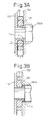
- Figure 3A is an enlarged section of the sealing arrangement according to an embodiment of the invention when a screw bolt of a yoke type clamping means of the flow regulator is not tightened;
- Figure 3B is an enlarged section similar to Figure 3A in which the screw bolt is tightened;
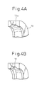
- Figure 4A is a partially sectional perspective view which shows a portion of a protection ring according to an embodiment of the invention;
- Figure 4B is a partially sectional perspective view which shows a portion of a protection ring according to another embodiment of the invention
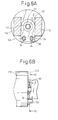
- Figure 5A is a front view of the sealing arrangement of an embodiment of the invention along line V-V in Figure 5B;
- Figure 5B is a section of the sealing arrangement of Figure 5A;
- Figure 6A is a front view of the sealing arrangement of another embodiment of the invention along line VI-VI in Figure 6B;
- Figure 6B is a section of the sealing arrangement of Figure 6A;
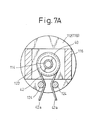
- Figure 7A is a front view of the sealing arrangement of another embodiment of the invention along line VII-VII in Figure 7B;
- Figure 7B is a side view of the sealing arrangement of Figure 7A;
- Figure 7C is a section of a protection ring of the embodiment shown in Figures 7A and 7B;
- Figure 8 is front view of a clip according to an embodiment of the invention;
- Figure 9A is a section, similar to Figure 3A, of the sealing arrangement according to a prior art; and
- Figure 9B is an enlarged section, similar to Figure 3B, of the sealing arrangement according to a prior art.
-
- Figures 1 and 2 show an
oxygen cylinder 100 which contains high pressure oxygen gas or an oxygen enhanced gas. The oxygen cylinder is provided with a shut-offvalve 102 which is adapted to CGA (Compressed Gas Association) 870. The shut-offvalve 102 includes acasing 104 for accommodating a valve body (not shown) movable between an open position and a closed position, acock 105 for manipulating the valve body between the open and closed positions and apressure gage 103 for indicating the pressure in theoxygen cylinder 100. Aside wall 106 of thecasing 104 includes a pair ofpositioning recesses 106a for positioning aflow regulator 110 which is attached to the shut-offvalve 102. Theside wall 106 further includes a outlet port 106b for discharging the oxygen gas when the valve body is in the open position. - The
flow regulator 110 includes acylindrical body 112 having first and second end faces 112a and 112b. Aninlet port 114 and a pair of positioning pins 124 extend from thefirst end face 112a so as to be inserted into the outlet port 106b and the positioning recesses 106a of the shut-offvalve 102, respectively, when theflow regulator 110 is attached to the shut-offvalve 102. The positioning pins 124 are generally made of a metallic material and, in particular, are made of a stainless steel. The engagement between the metallic positioning pins 124 and thepositioning recesses 106a displaces theflow regulator 110 in place relative to the shut-offvalve 102. Anoutlet port 118 is connected to thecylindrical body 112 adjacent thesecond end face 112b. Ayoke 116 is connected to thefirst end face 112a of thecylindrical body 112. Theyoke 116 has a threadedhole 116a with which ascrew bolt 120 engages, as shown in Figure 1. Tightening thescrew bolt 120 clamps the shut-offvalve 102 between theend 120a of thescrew bolt 120 and thefirst end face 112a of thecylinder body 112 to secure theflow regulator 110 to the shut-offvalve 102. - The
outlet port 118 is adapted to be fluidly connected, through a conduit or a tube (not shown), to a nasal cannula or a nasal mask (not shown) which is attached to the nose of the patient. An aspiration sensor (not shown) is provided for detecting the aspiration of the patient. Thecylindrical body 112 of theflow regulator 110 contains an on-off valve (not shown) which is fluidly connected to the inlet andoutlet ports outlet ports - Referring to Figures 3A and 3B, when the
flow regulator 110 is attached to the shut-offvalve 102, theinlet port 114 is inserted into theoutlet port 106a of the shut-offvalve 102, as shown in Figure 3A. Provided around theinlet port 114 of theflow regulator 110 is a sealing member, in this particular embodiment an o-ring 122 which is clamped between thefirst end face 112a of thecylindrical body 112 and theside wall 106 of the shut-offvalve 102 to seal between theflow regulator 110 and the shut-offvalve 102. According to a feature of the invention, the o-ring 122 can preferably be made of an electrically conductive rubber material which has a volumetric resistivity of not more than 1.0×10¹⁰ Ωcm, preferably not more than 1.0×10⁷ Ωcm, and more preferably not more than 1.0×10⁶ Ωcm, for example a fluorocarbon elastomer in which carbon particles are added, as a conductive material, to enhance the conductivity or a chloroprene rubber material. The small volumetric resistivity or the conductivity of the o-ring 122 allows the static electricity charged in the o-ring 122 to be discharged directly to thecylindrical body 112 of theflow regulator 110 and the shut-offvalve 102. Therefore, in case the case that the o-ring 122 is made of electrically conductive rubber material, the metallic protection member can be replaced with a protection member made of a high-strength engineering plastic material. - An experiment was executed to measure the static electric voltage induced in the
protection ring 10, in which three type of o-rings were used. The o-rings were made of poly (vinylidene fluoride-hexafluoropropylene), available as Viton from DuPont (Example 1); Viton base carbon enhanced fluorocarbon elastomer (Example 2); and chloroprene (Example 3), respectively. The experiment results were shown in Table 1.Volumetric Resistivity (Ωcm) (Method of Measurement) Static Electricity (V) Example 1 2.5×10¹³ (JIS K6911) 500 Example 2 Less Than 1.0×10⁶ (JIS K6911) 0 6.2 (SRIS 2301) Example 3 1.2×10⁷ (JIS K6911) 0 - In the experiment, the volumetric resistivity was measured in accordance with JIS K6911 (Ambient temperature 23 °C;
relative humidity 50 %). In this connection, according to JIS K6911, the static electricity induced in the protection ring could not measured in the case of Example 2 because the static electricity was below the lower measurable limit. Therefore, the measurement was carried out in accordance with SRIS 2301 for Example 2. - A metallic protection member, made of brass material, steel material, or aluminum material, is provided around the o-
ring 122. In an preferred embodiment, the protection member comprises aprotection ring 10. Theprotection ring 10 preferably has a thickness T which is smaller than the diameter D of the section of the o-ring 122 so that the o-ring can contact both thefirst end face 112a of thecylinder body 112 of theflow regulator 110 and theside wall 106 of the shut-offvalve 102 to provide a sealing effect. The thickness T must be sufficient to allow theprotection ring 10 to contact thefirst end face 112a of thecylinder body 112 of theflow regulator 110 and theside wall 106 of the shut-offvalve 102, as shown in Figure 3B, when thescrew bolt 120 is tightened to attach theflow regulator 110 to the shut-off valve. This allows theprotection ring 10 to be grounded to thecylindrical body 112 of theflow regulator 110 and/or the shut-offvalve 102 so that the electric potential induced in theprotection ring 10 relative to theflow regulator 110 and the shut-offvalve 102 by the static electricity charged in the o-ring 122 is reduced. An experiment shows that a thickness T of theprotection ring 10 larger than 80 % of the thickness of the sealing member or the diameter D of the o-ring 122 allows theprotection ring 10 to contact thefirst end face 112a of thecylinder body 112 of theflow regulator 110 and theside wall 106 of the shut-offvalve 102. Figures 9A and 9B show a prior art, in which an insufficient thickness T' of the protection ring 10' prevents the protection ring 10' from contacting thecylindrical body 112 of theflow regulator 110 or thecasing 104 of the shut-offvalve 102. - With reference to Figure 4A, the
protection ring 10 includes an inner peripheral groove 10a for snugly holding the o-ring 122. The inner peripheral groove 10a has a rounded section, as shown Figure 4A. However, the shape of the inner peripheral groove is not limited to this and may be formed into a polygonal shape, for example a trapezoid shape, as shown by reference "12" in Figure 4B. - In the previous embodiments, the protection member is formed into a ring. However, the present invention is not limited to this configuration.
- With reference to Figures 5A and 5B, a modified embodiment of the protection member is shown. In the embodiment shown in Figure 5A, the protection member comprises a
protection plate 20 which includes acentral hole 22 for receiving the o-ring 122 and a pair of positioning holes 24 for receiving the metallic positioning pins 124. Engagement between the metallic positioning pins 124 and the positioning holes 24 displaces theprotection plate 20 relative to theflow regulator 110 and the shut-offvalve 102. Engagement therebetween further provides a ground circuit for theprotection plate 20 to theflow regulator 110 and the shut-offvalve 102 through the metallic positioning pins 124. The electric potential induced in theprotection plate 20 relative to theflow regulator 110 and the shut-offvalve 102 by the static electricity charged in the o-ring 122 is reduced through the ground circuit. This configuration is advantageous when thecylindrical body 112 of theflow regulator 110 and/or the shut-offvalve 102 is a made of non-electrically-conductive material. In particular, when thecylindrical body 112 of theflow regulator 110 and/or the shut-offvalve 102 is made of aluminum material, their surfaces are often coated by an aluminum oxide which prevents the conductivity of thecylindrical body 112 of theflow regulator 110 and/or the shut-offvalve 102. Even in that case, the ground circuit provided by the engagement between the positioning holes 24 and the metallic positioning pins 124 reduces the electric potential induced in theprotection plate 20. Therefore, a spark is prevented when theflow regulator 110 is detached from the shut-offvalve 102. In this connection, according to this embodiment, the thickness of theprotection plate 20 must be smaller than that of the o-ring 122, however, it is not required to be larger than 80% of that of the o-ring 122. - In an embodiment shown in Figures 6 A and 6B, the protection member comprises a
protection plate 30. Theprotection plate 30 includes acentral hole 32 for receiving the o-ring 122 and a pair of positioning holes 34 for receiving the metallic positioning pins 124. Engagement between the metallic positioning pins 124 and the positioning holes 34 displaces theprotection plate 30 and provides an electric circuit for discharging the static electricity charged in the o-ring 122 from the o-ring 122 to theflow regulator 110 and the shut-offvalve 102 through theprotection plate 30 and the metallic positioning pins 124. In this connection, according to this embodiment, the thickness of theprotection plate 30 must be also smaller than that of the o-ring 122, however, it is not required to be larger than 80% of that of the o-ring 122. - Figures 7A - 7C show another embodiment of the protection member. In this embodiment, the protection member comprises a
protection ring 40. Theprotection ring 40 includes an innerperipheral grove 40a for snugly holding the o-ring 122 and a outerperipheral groove 40b for engagement with ametallic clip 42. Themetallic clip 42 are preferably made of a stainless steel spring material, and includesarm portions 42a which are adapted to engage the metallic positioning pins 124. According to this embodiment, engagement between thearm portions 42a and the metallic positioning pins 124 displaces theprotection ring 40 and provides a ground circuit for theprotection ring 40 to theflow regulator 110 and the shut-offvalve 102 through themetallic clip 42 and the positioning pins 124. In this connection, according to this embodiment, the thickness of theprotection ring 40 must be also smaller than that of the o-ring 122, however, it is not required to be larger than 80% of that of the o-ring 122. - Figure 8 shows another embodiment, in which the
metallic clip 42 is replaced with ametallic clip 50. Themetallic clip 50 has a pair ofarm portions 52 which are adapted to be rounded around the metallic positioning pins 24 when themetallic clip 50 is assembled to theflow regulator 110. - It will also be understood by those skilled in the art that the forgoing description is a preferred embodiment of the disclosed device and that various changes and modifications may be made without departing from the spirit and scope of the invention.
Claims (11)
- An arrangement for sealing between a flow regulator and a shut-off valve attached to an oxygen cylinder, the shut-off valve including a casing which is adapted to be mounted to an oxygen cylinder containing oxygen gas or an oxygen enhanced gas, a side wall defining a part of the casing, a female outlet port defined in the side wall of the casing, the flow regulator including a metallic cylindrical body having first and second end faces, a yoke extending from the first end face of the cylindrical body, and a screw bolt having an end facing the first end face of the cylindrical body, the screw bolt operated with the yoke to clamp the casing of the shut-off valve between the first end face of the cylindrical body and the end of the screw bolt, the arrangement comprising;a male inlet port, extending from the first end face of the cylindrical body, for receiving the oxygen gas or the oxygen enhanced gas from the outlet port of the shut-off valve when the flow regulator is attached to the shut-off valve; anda sealing member, provided around the inlet port of the flow regulator so that the sealing member is clamped between the first end face of the cylindrical body of the flow regulator and the casing of the shut-off valve when the flow regulator is secured to the shut-off valve, for sealing between the inlet port and the casing of the shut-off valve around the outlet port, the sealing member being made of an electrically conductive rubber material.
- An arrangement according to claim 1, wherein the rubber material has a volumetric resistivity of not more than 1.0×10¹⁰ Ωcm.
- An arrangement according to claim 1 or 2, wherein the sealing member comprises an o-ring provided around the inlet port;the arrangement further comprising a metallic protection member, provided around the o-ring, for protecting the o-ring from wear and tear; andthe o-ring being made of a rubber material having a volumetric resistivity of not more than 1.0×10¹⁰ Ωcm.
- An arrangement for sealing between a flow regulator and a shut-off valve attached to an oxygen cylinder, the shut-off valve including a casing which is adapted to be mounted to an oxygen cylinder for containing oxygen gas or an oxygen enhanced gas, a side wall defining a part of the casing, a female outlet port defined in the side wall of the casing, and a positioning recess defined in the side wall of the casing, the flow regulator including a metallic cylindrical body having first and second end faces, and a metallic positioning pin, extending from the first end of the cylindrical body to engage the positioning recess of the shut-off valve, a yoke extending from the first end of the cylindrical body, and a screw bolt having an end facing the first end of the cylindrical body, the screw bolt operated with the yoke to clamp the casing of the shut-off valve between the first end face of the cylindrical body and the end of the screw bolt, the arrangement comprising;a male inlet port, extending from the first end face of the cylindrical body, for receiving the oxygen gas or the oxygen enhanced gas from the outlet port of the shut-off valve when the flow regulator is attached to the shut-off valve;a sealing member, provided around the inlet port of the flow regulator so that the o-ring is clamped between the first end face of the cylindrical body of the flow regulator and the casing of the shut-off valve when the flow regulator is secured to the shut-off valve, for sealing between the inlet port and the casing of the shut-off valve around the outlet port; anda metallic protection member, provided around the sealing member, for protecting the sealing member from wear and tear, the metallic protection member having a thickness which allows the metallic protection member to contact the first end of the cylindrical body of the flow regulator and/or the side wall of the shut-off valve.
- An arrangement according to claim 4, wherein the thickness of the metallic protection member is smaller than that of the sealing member and larger than 80% of that of the sealing member.
- An arrangement according to claim 4 or 5, wherein the sealing member comprises an o-ring provided around the inlet port of the flow regulator, and the metalic protection member comprises a protection ring provided around the o-ring.
- An arrangement according to claim 6, wherein the protection ring includes an inner peripheral groove for snugly holding the o-ring.
- An arrangement according to claim 7, wherein the inner peripheral groove of the protection ring has a rounded sectional shape having a radius of curvature larger than that of the section of the o-ring.
- An arrangement according to claim 7, wherein the inner peripheral groove of the protection ring has a polygonal sectional shape.
- An arrangement according to claim 4, wherein the sealing member comprises an o-ring provided around the inlet port of the flow regulator; and
the metallic protection member comprising a protection plate provided around the o-ring, the protection plate including a positioning holes engaging the metallic positioning pin of the flow regulator to provide an electric circuit for discharging the static electricity charged in the o-ring. - An arrangement according to claim 4, wherein the sealing member comprises an o-ring provided around the inlet port of the flow regulator;the metallic protection member comprising a protection ring provided around the o-ring; andthe arrangement further comprising a metallic clip provided around the protection ring, the metallic clip including an arm portion engaging the metallic positioning pin of the flow regulator to provide an electric circuit for discharging the static electricity charged in the o-ring.
Applications Claiming Priority (6)
| Application Number | Priority Date | Filing Date | Title |
|---|---|---|---|
| JP2000021595A JP3986722B2 (en) | 2000-01-31 | 2000-01-31 | Breathing gas supply device |
| JP2000021594 | 2000-01-31 | ||
| JP2000021595 | 2000-01-31 | ||
| JP2000021594A JP4422271B2 (en) | 2000-01-31 | 2000-01-31 | Breathing gas supply device |
| JP2000026010 | 2000-02-03 | ||
| JP2000026010A JP2001212238A (en) | 2000-02-03 | 2000-02-03 | Respiratory gas supply device |
Publications (3)
| Publication Number | Publication Date |
|---|---|
| EP1122474A2 true EP1122474A2 (en) | 2001-08-08 |
| EP1122474A3 EP1122474A3 (en) | 2002-09-04 |
| EP1122474B1 EP1122474B1 (en) | 2005-10-26 |
Family
ID=27342184
Family Applications (1)
| Application Number | Title | Priority Date | Filing Date |
|---|---|---|---|
| EP01102112A Expired - Lifetime EP1122474B1 (en) | 2000-01-31 | 2001-01-31 | Sealing arrangement between flow regulator and shut-off valve attached to oxygen cylinder |
Country Status (3)
| Country | Link |
|---|---|
| US (1) | US6416036B2 (en) |
| EP (1) | EP1122474B1 (en) |
| DE (1) | DE60114258T2 (en) |
Cited By (4)
| Publication number | Priority date | Publication date | Assignee | Title |
|---|---|---|---|---|
| CN102679067A (en) * | 2012-04-09 | 2012-09-19 | 山东电力集团公司烟台供电公司 | Special exhaust SF6 equipment inflating joint with adjustable pressure protection function |
| CN103182124A (en) * | 2011-12-30 | 2013-07-03 | 北京谊安医疗系统股份有限公司 | Gas cylinder holding device for anesthesia machine |
| CN103375968A (en) * | 2012-04-27 | 2013-10-30 | 林德股份公司 | Piping module for air fractionation plant |
| CN110312891A (en) * | 2016-12-29 | 2019-10-08 | A·A·舒巴 | Improved antistatic pressure tank |
Families Citing this family (8)
| Publication number | Priority date | Publication date | Assignee | Title |
|---|---|---|---|---|
| US20040102749A1 (en) * | 2002-11-21 | 2004-05-27 | Kimberly-Clark Worldwide, Inc. | Absorbent article with low coefficient of friction between materials of differential tensions |
| US6837270B2 (en) | 2002-11-26 | 2005-01-04 | Andrew S. Douglas | Gas delivery system and pneumatic yoke for a pressurized gas reservoir |
| CN103182131B (en) * | 2011-12-30 | 2015-12-02 | 北京谊安医疗系统股份有限公司 | Choke valve |
| USD746440S1 (en) * | 2013-09-04 | 2015-12-29 | African Oxygen Limited | Encapsulated valve for a medical integrated valve |
| US20160257460A1 (en) * | 2015-03-06 | 2016-09-08 | Micro Matic Usa, Inc. | Static Dissipating Downtube And Valve |
| CN106501462A (en) * | 2016-12-15 | 2017-03-15 | 河南华瑞高新材料科技股份有限公司 | A kind of measurement apparatus of detection bottled gas moisture |
| USD963827S1 (en) * | 2020-09-10 | 2022-09-13 | Puzhen Life Co., Ltd | Aroma diffuser |
| US12180690B1 (en) * | 2020-11-05 | 2024-12-31 | Vista Water Group, Llc | Backflow preventer |
Family Cites Families (18)
| Publication number | Priority date | Publication date | Assignee | Title |
|---|---|---|---|---|
| US3147761A (en) * | 1961-12-19 | 1964-09-08 | Sportsways Inc | Regulator for underwater breathing apparatus |
| US3249119A (en) * | 1962-11-15 | 1966-05-03 | Nathan M Pollack | Seal assembly |
| US4142973A (en) * | 1977-02-17 | 1979-03-06 | Facet Enterprises, Inc. | Valve with indicator circuit |
| US4292841A (en) * | 1979-07-11 | 1981-10-06 | Creative Tool Company | Compression rate analyzer |
| JPH0311560Y2 (en) * | 1986-12-25 | 1991-03-20 | ||
| IT224295Z2 (en) * | 1991-03-08 | 1996-03-14 | Scubapro Europ | VALVE, IN PARTICULAR FOR DIVING SCUBA BREATHERS. |
| US5282493A (en) * | 1993-01-07 | 1994-02-01 | Contemporary Products, Inc. | High pressure fluid valve |
| US5411348A (en) * | 1993-10-26 | 1995-05-02 | Bal Seal Engineering Company, Inc. | Spring mechanism to connect, lock and unlock, members |
| JP3386138B2 (en) * | 1995-09-28 | 2003-03-17 | ネルコー ピューリタン ベネット インコーポレイテッド | Oxygen storage regulator device |
| US5704589A (en) * | 1995-10-12 | 1998-01-06 | Victor Equipment Company | Yoke for mounting on a gas tank |
| IT1287792B1 (en) * | 1996-06-05 | 1998-08-18 | Stefano Morino | FIRST STAGE REDUCER FOR TWO-STAGE DISPENSERS. |
| US5899223A (en) * | 1996-11-08 | 1999-05-04 | Precision Medical, Inc. | Compact gas pressure regulator |
| IT241616Y1 (en) * | 1996-11-08 | 2001-05-09 | Htm Sport Spa | FIRST STAGE REDUCER FOR TWO-STAGE RESPIRATORY APPLIANCES. |
| US5785050A (en) * | 1997-03-03 | 1998-07-28 | Davidson; Brian R. | Oxygen valve system |
| US5746198A (en) * | 1997-03-13 | 1998-05-05 | U.S. Divers Co., Inc. | Valve for a first stage regulator having an encapsulated head |
| IT1293461B1 (en) * | 1997-07-17 | 1999-03-01 | Skf Ind Spa | ROLLING BEARING WITH SEALING AND DISCHARGE DEVICE OF ELECTROSTATIC CURRENTS. |
| US6082396A (en) * | 1998-12-16 | 2000-07-04 | Davidson; Gilbert | Compressed gas regulator with flow control and internal gauge |
| US6158457A (en) * | 1999-05-18 | 2000-12-12 | Western/Scott Fetzer Company | Gas pressure control apparatus |
-
2001
- 2001-01-31 DE DE2001614258 patent/DE60114258T2/en not_active Expired - Lifetime
- 2001-01-31 US US09/772,984 patent/US6416036B2/en not_active Expired - Lifetime
- 2001-01-31 EP EP01102112A patent/EP1122474B1/en not_active Expired - Lifetime
Non-Patent Citations (1)
| Title |
|---|
| None |
Cited By (7)
| Publication number | Priority date | Publication date | Assignee | Title |
|---|---|---|---|---|
| CN103182124A (en) * | 2011-12-30 | 2013-07-03 | 北京谊安医疗系统股份有限公司 | Gas cylinder holding device for anesthesia machine |
| CN103182124B (en) * | 2011-12-30 | 2016-06-29 | 北京谊安医疗系统股份有限公司 | Anesthetic machine gas cylinder clamping device |
| CN102679067A (en) * | 2012-04-09 | 2012-09-19 | 山东电力集团公司烟台供电公司 | Special exhaust SF6 equipment inflating joint with adjustable pressure protection function |
| CN103375968A (en) * | 2012-04-27 | 2013-10-30 | 林德股份公司 | Piping module for air fractionation plant |
| CN103375968B (en) * | 2012-04-27 | 2017-04-12 | 林德股份公司 | Piping module for air fractionation plant |
| CN110312891A (en) * | 2016-12-29 | 2019-10-08 | A·A·舒巴 | Improved antistatic pressure tank |
| CN110312891B (en) * | 2016-12-29 | 2021-08-24 | A·A·舒巴 | Improved antistatic pressure tank |
Also Published As
| Publication number | Publication date |
|---|---|
| US6416036B2 (en) | 2002-07-09 |
| DE60114258D1 (en) | 2005-12-01 |
| EP1122474B1 (en) | 2005-10-26 |
| EP1122474A3 (en) | 2002-09-04 |
| US20010015419A1 (en) | 2001-08-23 |
| DE60114258T2 (en) | 2006-07-13 |
Similar Documents
| Publication | Publication Date | Title |
|---|---|---|
| US6416036B2 (en) | Sealing arrangement between flow regulator and shut-off valve attached to oxygen cylinder | |
| US11543038B2 (en) | Dense phase pump with easily replaceable components | |
| US6739578B2 (en) | Coupling mechanism and valve system for a pressurized fluid container | |
| US20140251455A1 (en) | Pressurized gas containing system | |
| JP2004505692A (en) | Apparatus and method for connecting respiratory device parts | |
| CA2394442A1 (en) | Gas suction pump device, gas feed adapter and gas alarm unit | |
| EP1129743A3 (en) | Filter | |
| US20150000669A1 (en) | Fluid inlet adapter | |
| MXPA02012556A (en) | Connector for a compressed-gas canister and a fastening appliance. | |
| US11549612B1 (en) | Valve core removal tool fixture with slide valve | |
| EP1595124B1 (en) | Gauge pressure sensor hazardous applications | |
| US20020002998A1 (en) | Two-way valve | |
| CN116327275A (en) | Gas delivery system and its data processing method | |
| US5417204A (en) | Scuba air contamination detector | |
| US7584751B1 (en) | Adapter for protective mask testing apparatus | |
| US20070051185A1 (en) | Sensor with water ingress protection | |
| CN211301591U (en) | Adapter for replacing filter at exhalation end without disconnecting respirator | |
| DE60215955D1 (en) | DEVICE FOR THE QUANTITATIVE ANALYSIS OF BREATHING GASES | |
| US7837935B2 (en) | Joint for joining hydrogen gas running route-forming members and portable hydrogen flame ionization gas detector | |
| WO1996007568A1 (en) | Airline handset for tyre inflation apparatus | |
| CN220632789U (en) | Air respirator gas cylinder | |
| CN114733018B (en) | Pneumoperitoneum device | |
| US20250198528A1 (en) | Reciprocating switch for high-pressure fluid lines | |
| US20250129895A1 (en) | Fluid container provided with a dispensing valve with an electronic device retained by a protective cover | |
| JPH0545541U (en) | Main valve of pressure gauge |
Legal Events
| Date | Code | Title | Description |
|---|---|---|---|
| PUAI | Public reference made under article 153(3) epc to a published international application that has entered the european phase |
Free format text: ORIGINAL CODE: 0009012 |
|
| AK | Designated contracting states |
Kind code of ref document: A2 Designated state(s): AT BE CH CY DE DK ES FI FR GB GR IE IT LI LU MC NL PT SE TR |
|
| AX | Request for extension of the european patent |
Free format text: AL;LT;LV;MK;RO;SI |
|
| PUAL | Search report despatched |
Free format text: ORIGINAL CODE: 0009013 |
|
| AK | Designated contracting states |
Kind code of ref document: A3 Designated state(s): AT BE CH CY DE DK ES FI FR GB GR IE IT LI LU MC NL PT SE TR |
|
| AX | Request for extension of the european patent |
Free format text: AL;LT;LV;MK;RO;SI |
|
| RIC1 | Information provided on ipc code assigned before grant |
Free format text: 7F 16K 1/30 A, 7F 17C 13/12 B, 7F 17C 13/04 B, 7F 16J 15/12 B, 7F 16J 15/06 B |
|
| 17P | Request for examination filed |
Effective date: 20030203 |
|
| AKX | Designation fees paid |
Designated state(s): DE FR GB |
|
| 17Q | First examination report despatched |
Effective date: 20040503 |
|
| GRAP | Despatch of communication of intention to grant a patent |
Free format text: ORIGINAL CODE: EPIDOSNIGR1 |
|
| GRAS | Grant fee paid |
Free format text: ORIGINAL CODE: EPIDOSNIGR3 |
|
| GRAA | (expected) grant |
Free format text: ORIGINAL CODE: 0009210 |
|
| AK | Designated contracting states |
Kind code of ref document: B1 Designated state(s): DE FR GB |
|
| REG | Reference to a national code |
Ref country code: GB Ref legal event code: FG4D |
|
| REF | Corresponds to: |
Ref document number: 60114258 Country of ref document: DE Date of ref document: 20051201 Kind code of ref document: P |
|
| ET | Fr: translation filed | ||
| PLBE | No opposition filed within time limit |
Free format text: ORIGINAL CODE: 0009261 |
|
| STAA | Information on the status of an ep patent application or granted ep patent |
Free format text: STATUS: NO OPPOSITION FILED WITHIN TIME LIMIT |
|
| 26N | No opposition filed |
Effective date: 20060727 |
|
| REG | Reference to a national code |
Ref country code: FR Ref legal event code: PLFP Year of fee payment: 16 |
|
| REG | Reference to a national code |
Ref country code: FR Ref legal event code: PLFP Year of fee payment: 17 |
|
| PGFP | Annual fee paid to national office [announced via postgrant information from national office to epo] |
Ref country code: FR Payment date: 20170127 Year of fee payment: 17 Ref country code: DE Payment date: 20170125 Year of fee payment: 17 |
|
| PGFP | Annual fee paid to national office [announced via postgrant information from national office to epo] |
Ref country code: GB Payment date: 20170126 Year of fee payment: 17 |
|
| REG | Reference to a national code |
Ref country code: DE Ref legal event code: R119 Ref document number: 60114258 Country of ref document: DE |
|
| GBPC | Gb: european patent ceased through non-payment of renewal fee |
Effective date: 20180131 |
|
| PG25 | Lapsed in a contracting state [announced via postgrant information from national office to epo] |
Ref country code: FR Free format text: LAPSE BECAUSE OF NON-PAYMENT OF DUE FEES Effective date: 20180131 Ref country code: DE Free format text: LAPSE BECAUSE OF NON-PAYMENT OF DUE FEES Effective date: 20180801 |
|
| REG | Reference to a national code |
Ref country code: FR Ref legal event code: ST Effective date: 20180928 |
|
| PG25 | Lapsed in a contracting state [announced via postgrant information from national office to epo] |
Ref country code: GB Free format text: LAPSE BECAUSE OF NON-PAYMENT OF DUE FEES Effective date: 20180131 |