EP1122321B1 - Dual Laser shock peening - Google Patents
Dual Laser shock peening Download PDFInfo
- Publication number
- EP1122321B1 EP1122321B1 EP01300696A EP01300696A EP1122321B1 EP 1122321 B1 EP1122321 B1 EP 1122321B1 EP 01300696 A EP01300696 A EP 01300696A EP 01300696 A EP01300696 A EP 01300696A EP 1122321 B1 EP1122321 B1 EP 1122321B1
- Authority
- EP
- European Patent Office
- Prior art keywords
- article
- laser
- spots
- spot
- alignment vector
- Prior art date
- Legal status (The legal status is an assumption and is not a legal conclusion. Google has not performed a legal analysis and makes no representation as to the accuracy of the status listed.)
- Expired - Lifetime
Links
Images


Classifications
-
- C—CHEMISTRY; METALLURGY
- C21—METALLURGY OF IRON
- C21D—MODIFYING THE PHYSICAL STRUCTURE OF FERROUS METALS; GENERAL DEVICES FOR HEAT TREATMENT OF FERROUS OR NON-FERROUS METALS OR ALLOYS; MAKING METAL MALLEABLE, e.g. BY DECARBURISATION OR TEMPERING
- C21D10/00—Modifying the physical properties by methods other than heat treatment or deformation
- C21D10/005—Modifying the physical properties by methods other than heat treatment or deformation by laser shock processing
Landscapes
- Chemical & Material Sciences (AREA)
- Physics & Mathematics (AREA)
- Engineering & Computer Science (AREA)
- Optics & Photonics (AREA)
- Thermal Sciences (AREA)
- Crystallography & Structural Chemistry (AREA)
- Mechanical Engineering (AREA)
- Materials Engineering (AREA)
- Metallurgy (AREA)
- Organic Chemistry (AREA)
- Laser Beam Processing (AREA)
- Knitting Machines (AREA)
Description
- This invention is generally related to laser shock peening and, more particularly, is related to a method and system for controlling dual laser shock peening of an article.
- Gas turbine engines and, in particular, aircraft gas turbine engines rotors operate at high rotational speeds that produce high tensile and vibratory stress fields within the blade and make the fan blades susceptible to foreign object damage (FOD). Vibrations may also be caused by vane wakes and inlet pressure distortions as well as other aerodynamic phenomena. This FOD causes nicks and tears and hence stress concentrations in leading and trailing edges of fan blade airfoils. These nicks and tears become the source of high stress concentrations or stress risers and severely limit the life of these blades due to High Cycle Fatigue (HCF) from vibratory stresses.
- Thus, it is highly desirable to design and construct longer lasting fan and compressor blades, as well as other hard metallic parts, that are better able to resist both low and high cycle fatigue and that can arrest cracks better than present day parts. The below referenced U.S. Patent Applications or U.S. Patents are directed towards this end: U. S. patent application Serial Nos.
08/993,194 , pending, entitled "Laser Shock Peening Using Low Energy Laser";08/362,362 , "On The Fly Laser Shock Peening", filed December 22, 1994, now abandoned; and U. S. Pat. No.:5,591,009 , entitled "Laser Shock Peened Gas Turbine Enginer Fan Blade Edges"; U. S. Patent No.5,569,018 , entitled "Technique To Prevent Or Divert Cracks"; U. S. Patent No.5,531,570 , entitled "Distortion Control For Laser Shock Peened Gas Turbine Engine Compressor Blade Edges"; U. S. Patent No.5,492,447 , entitled "Laser Shock Peened Rotor Components For Turbomachinery"; U. S. Patent No.5,674,329 , entitled "Adhesive Tape Covered Laser Shock Peening"; and U. S. Patent No.5,674,328 , entitled "Dry Tape Covered Laser Shock Peening", all of which are assigned to the present Assignee. They teach to provide an airfoil of a fan blade with a continuous or volumetric region of deep compressive residual stresses imparted by laser shock peening over at least an inwardly extending portion of laser shock peened surfaces of an article, such as the fan blade. These regions are formed by multiple overlapping protrusions of compressive residual stresses imparted by laser shock peening that extend inward from overlapping laser shock peened circles or spots. - The deep compressive residual stresses imparted by laser shock peening of the present invention is not to be confused with a surface layer zone of a work piece that contains locally bounded compressive residual stresses that are induced by a hardening operation using a laser beam to locally heat and thereby harden the work piece such as that which is disclosed in
U.S. Pat. No. 5,235,838 , entitled "Method and apparatus for truing or straightening out of true work pieces". The prior art teaches the use of multiple radiation pulses from high powered pulsed lasers and large laser spot diameters of about 1 cm to produce shock waves on the surface of a work piece similar like the above referenced Patent Applications andU.S. Pat. No. 3,850,698 , entitled "Altering Material Properties";U.S. Pat. No. 4,401,477 , entitled "Laser shock processing"; andU.S. Pat. No. 5,131,957 , entitled "Material Properties". Laser shock peening as understood in the art and as used herein, means utilizing a laser beam from a laser beam source to produce a continuous region of strong compressive residual stresses in a continuous region on a portion of a surface. The region is volumetric and produced by the coalescence of individual protrusions extending inward from overlapping laser shock peened circles or spots. Laser peening has been utilized to create a compressively stressed protection layer at the outer surface of a workpiece which is known to considerably increase the resistance of the workpiece to fatigue failure as disclosed inU.S. Pat. No. 4,937,421 , entitled "Laser Peening System and Method". Manufacturing costs of the laser shock peening process is a great area of concern because startup and operational costs can be very expensive. The "on the fly" laser shock peening process disclosed in08/362,362 , above is designed to provide cost saving methods for laser shock peening as is the present invention. Prior art teaches to use large laser spots, on the order of 1 cm and greater in diameter, and high powered lasers. Manufacturers are constantly seeking methods to reduce the time, cost, and complexity of such processes. A laser shock peening method that uses a low power laser beam, on the order of 3-10 joules, with a preferred range of 3-7 Joules and laser beam spots having a diameter of about 1 mm is disclosed in co-pendingU.S. patent application No. 08/993,194 , entitled "Laser Shock Peening Using Low Energy Laser" and this method is directed to reducing time, cost, and complexity of laser shock peening. There is an ever present desire to design techniques that result in such reductions and to this end the present invention is directed. - As suggested above, known prior art laser peening techniques have been solely concerned with the use of a single laser beam that struck the surface to be peened at a designated position, at a designated angle. Recent advances in laser shock peening technology may require that the article be simultaneously struck on mutually opposite surfaces so that the respective shock waves created by the two impinging laser beams meet at the center of the opposite surfaces. See U. S. Patent No.
6,005,219 , issued to the same Assignee of the present invention and herein incorporated by reference. Manufacturing use of this dual laser technique imposes a need for developing programmable tools, such as numerical control (NC) tools, that allow for accurately, reliably and inexpensively controlling the dual laser peening process. - Thus, it is desirable to be able to provide an automated process for developing commands for controlling a dual laser shock peening device using presently available NC part-positioning technology. It is further desirable to be able to accurately and quickly position the article relative to the dual laser beams so that each laser beam simultaneously impinges on a respective spot situated on either of the mutually opposite surfaces. Since the respective spots which are simultaneously struck by the two laser beams lie opposite one another on mutually opposite surfaces of the article, it is also desirable to be able to determine the precise location of the spots at which the beams must strike the article to achieve a desired surface coverage and strong compressive residual stresses. As suggested above, it would also be desirable to be able to determine the command strategy, e.g., NC commands, to be programmed into the article-positioning device to three-dimensionally align the article to spatial locations that achieve the appropriate coverage.
- According to a first aspect of the invention, there is provided a method for dual laser shock peening an article, the method comprising defining a spot pattern comprising a plurality of spots on a first surface of the article to be peened; defining a spot pattern comprising a plurality of spots on a second surface of the article to be peened, the first and second surfaces comprising mutually opposite surfaces relative to one another, each one of the respective spots on the second surface being arranged to correspond to a respective spot on the first surface and comprising a plurality of matched pair of spots; and generating dual laser beams being respectively aligned to simultaneously impinge on each respective matched pair of spots; wherein a three dimensional alignment of the dual laser beams relative to the article comprises: defining an article alignment vector and an article working plane along which the article alignment vector is situated; defining a laser alignment vector and a laser working plane along which the laser alignment vector is situated; executing relative rotation between the article working plane and the laser working plane to provide parallel alignment between the article alignment vector and the laser alignment vector; and executing relative translation motion between the article and the dual laser beams so that one of the laser beams coincides with the center point of the spot on the first surface and the other of the laser beams coincides with the center point of the spot on the second surface.
- The first surface may comprise a convex surface.
- The spot pattern on the first surface may comprises a plurality of overlapping spots.
- The method may further comprise a step of selectively controlling the level of overlapping between adjacent spots.
- The second surface may comprise a concave surface.
- Each respective matched pair of spots may be situated relative to one another so that a line being normal relative to the spot on the first surface intersects a line being normal relative to the spot on the second surface, the intersection occurring at a point equidistant from each spot.
- The step of defining the spot pattern on the first surface may comprise defining a plurality of curves respectively traversing the convex surface of the article generally perpendicular to a longitudinal axis of the article.
- The separation between adjacent curves may be selected to be no longer than a desired center-to-center spacing between adjacent spots along the longitudinal axis.
- The selected separation between adjacent curves may determine the level of spot overlapping along the longitudinal axis.
- The step of defining the spot pattern on the first surface may further comprise defining a plurality of points along each of the respective curves, the separation between adjacent points being selected to be no longer than a desired center-to-center spacing between adjacent spots along the axis generally perpendicular to the longitudinal axis.
- The selected separation between adjacent points may determine the level of spot overlapping along the axis generally perpendicular to the longitudinal axis.
- The method may further comprise a step of defining respective points corresponding to the centers of each matched pair of spots.
- The method may further comprise a step of defining an article alignment vector and an article working plane along which the article alignment vector is situated.
- The method may further comprise a step of defining a laser alignment vector and a laser working plane along which the laser alignment vector is situated.
- The method may further comprise a step of executing relative rotation between the article working plane and the laser working plane to provide parallel alignment therebetween.
- The method may further comprise a step of executing relative rotation between the part alignment vector and the laser alignment vector to provide parallel alignment therebetween.
- The method may further comprising a step of executing relative translation motion between the article and the dual laser beams so that one of the laser beams coincides with the center point of the spot on the first surface and the other of the laser beams coincides with the center point of the spot on the second surface.
- According to a second aspect of the invention, there is provided an apparatus system for dual laser shock peening an article, the system comprising a spot pattern generator for defining a spot pattern comprising a plurality of spots on a first surface of the article to be peened, the pattern generator further defining a spot pattern comprising a plurality of spots on a second surface of the article to be peened, the first and second surfaces comprising mutually opposite surfaces relative to one another, each one of the respective spots on the second surface being arranged to correspond to a respective spot on the first surface and comprising a plurality of matched pair of spots; and a laser unit for generating dual laser beams being respectively aligned to simultaneously impinge on each respective matched pair of spots, characterised in that a three dimensional alignment of the dual laser beams relative to the article is performed by a processor comprising: a module for defining an article alignment vector and an article working plane along which the article alignment vector is situated; a module for defining a laser alignment vector and a laser working plane along which the laser alignment vector is situated; a module for executing relative rotation between the article working plane and the laser working plane to provide parallel alignment between the article alignment vector and the laser alignment vector; and a module for executing relative translation motion between the article and the dual laser beams so that one of the laser beams coincides with the center point of the spot on the first surface and the other of the laser beams coincides with the center point of the spot on the second surface.
- The first surface may comprise a convex surface.
- The spot pattern on the first surface comprises a plurality of overlapping spots.
- The system may further comprise an overlap control module for selectively controlling the level of overlapping between adjacent spots.
- The second surface may comprise a concave surface.
- Each respective matched pair of spots may be situated relative to one another so that a line normal relative to the spot on the first surface intersects a line normal relative to the spot on the second surface, the intersection occurring at a point equidistant from each spot.
- The spot pattern generator may include a module for defining a plurality of curves respectively traversing the convex surface of the article generally perpendicular to a longitudinal axis of the article.
- The separation between adjacent curves may be selected to be no longer than a desired center-to-center spacing between adjacent spots along the longitudinal axis.
- The selected separation between adjacent curves may determine the level of spot overlapping along the longitudinal axis.
- The module of the spot pattern generator may further define a plurality of points along each of the respective curves, the separation between adjacent points being selected to be no longer than the center-to-center spacing between adjacent spots along the axis generally perpendicular to the longitudinal axis.
- The selected separation between adjacent points may determine the level of spot overlapping along the axis generally perpendicular to the longitudinal axis.
- The system may further comprise a module for defining respective points corresponding to the centers of each matched pair of spots.
- The system may further comprise a module for defining an article alignment vector and an article working plane along which the article alignment vector is situated.
- The system may further comprise a module for defining a laser alignment vector and a laser working plane along which the laser alignment vector is situated.
- The system may further comprise means for executing relative rotation between the article working plane and the laser working plane to provide parallel alignment therebetween.
- The system may further comprise means for executing relative rotation between the part alignment vector and the laser alignment vector to provide parallel alignment therebetween.
- The system may further comprise means for executing relative translation motion between the article and the dual laser beams so that one of the laser beams coincides with the center point of the spot on the first surface and the other of the laser beams coincides with the center point of the spot on the second surface.
- Thus, generally speaking, the present invention fulfills the foregoing needs by providing a method for dual laser shock peening an article. The method allows for defining a spot pattern comprising a plurality of spots on a first surface of the article to be peened. The method further allows for defining a spot pattern comprising a plurality of spots on a second surface of the article to be peened. The first and second surfaces comprise mutually opposite surfaces relative to one another. Each one of the respective spots on the second surface is arranged to correspond to a respective spot on the first surface and comprising a plurality of matched pair of spots. A generating step allows for generating dual laser beams being respectively aligned to simultaneously impinge on each respective matched pair of spots.
- In another aspect of the invention, the foregoing needs are further fulfilled by providing a system for dual laser shock peening an article. The system comprises a spot pattern generator for defining a spot pattern comprising a plurality of spots on a first surface of the article to be peened. The pattern generator further defines a spot pattern comprising a plurality of spots on a second surface of the article to be peened. The first and second surfaces comprise mutually opposite surfaces relative to one another. Further, each one of the respective spots on the second surface is arranged to correspond to a respective spot on the first surface and comprises a plurality of matched pair of spots. A laser unit allows for generating dual laser beams that are respectively aligned to simultaneously impinge on each respective matched pair of spots.
- The invention will now be described in greater detail, by way of example, with reference to the drawings, in which:-
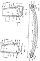
- FIG. 1 is a perspective illustrative view of an exemplary article, i.e., an aircraft gas turbine engine fan blade, that may be laser shock peened using the method and system of the present invention;
- FIG. 2 is a perspective illustrative view of another exemplary aircraft gas turbine engine fan blade that may be laser shock peened using the method and system of the present invention;
- FIG. 3 is a cross sectional view through the fan blade taken along
line 3--3 as illustrated in FIG. 2; - FIG. 4 is a flow chart of an exemplary embodiment of the method of the present invention that allows for determining the location of the spots at which respective dual laser beams strike mutually opposite surfaces of the article to be laser shock peened;
- FIG. 5 is a flow chart illustrating further details regarding exemplary spot patterns, e.g., overlapping spots, that may be generated by the method of the present invention;
- FIG. 6 is a flow chart illustrating steps for ensuring appropriate surface coverage of the article to be shock laser peened;
- FIG. 7 is a flow chart that provides details for controllably selecting the level of overlapping between adjacent spots;
- FIG. 8 is a plan view of an exemplary spot pattern that may be generated by the method of the present invention;
- FIG. 9 is an elevational view of the article to be laser shock peened that illustrates geometrical relationships between a matched pair of spots to be struck by the dual laser beams;
- FIG. 10 is a perspective view illustrating geometrical relationships for controllably selecting the level of overlapping between adjacent spots;
- FIG. 11 is a flowchart used to illustrate steps that allow for three-dimensionally aligning the article relative to the dual laser beams;
- FIG. 12 is an elevational view of the article to be laser shock peened that illustrates geometrical relationships for defining an article alignment vector, and an article working plane;
- FIG. 13 is an arrangement of exemplary dual laser beams that illustrates geometrical relationships for defining a laser alignment vector, and a laser working plane;
- FIG. 14 is an elevational view that results from the combination of FIGS. 12 and 13 upon three-dimensional alignment relative to one another;
- FIG. 15 is a schematic perspective view of the blade of FIG. 1 coated and mounted in a laser shock peening system for implementing the method of the present invention; and
- FIG. 16 is a partial cross-sectional and a partial schematic view of the setup of FIG. 15.
- Illustrated in FIGS. 1, 2 and 3, is a
fan blade 8 having anairfoil 34 made of a Titanium alloy extending radially outward from ablade platform 36 to ablade tip 38. This is representative of the type of hard metallic part and material that the method and system of the present invention was developed for. Thefan blade 8 includes aroot section 40 extending radially inward from theplatform 36 to a radiallyinward end 37 of theroot section 40. At the radiallyinward end 37 of theroot section 40 is ablade root 42 which is connected to theplatform 36 by ablade shank 44. Theairfoil 34 extends in the chordwise direction between a leading edge LE and a trailing edge TE of the airfoil. A chord C of theairfoil 34 is the line between the leading LE and trailing edge TE at each cross section of the blade as illustrated in FIG. 2. Apressure side 46 of theairfoil 34 faces in the general direction of rotation as indicated by the arrow and asuction side 48 is on the other side of the airfoil and a mean-line ML is generally disposed midway between the two faces in the chordwise direction. - The
fan blade 8 has aleading edge section 50 that extends along the leading edge LE of theairfoil 34 from theblade platform 36 to theblade tip 38. Theleading edge section 50 includes a predetermined first width W1 such that theleading edge section 50 encompassesnicks 52 and tears that may occur along the leading edge of theairfoil 34. Theairfoil 34 may be subject to a significant tensile stress field due to centrifugal forces generated by thefan blade 8 rotating during engine operation. Theairfoil 34 may also subject to vibrations generated during engine operation and thenicks 52 and tears operate as high cycle fatigue stress risers producing additional stress concentrations around them. - To counter fatigue failure of portions of the blade along possible crack lines that can develop and emanate from incipient cracks or micro-cracks, nicks, and tears, mutually opposite first and second surfaces or sides of the article, such as the
suction side 46 and thepressure side 48, have a respective laser shock peenedsurface area 54 witharrays 56 of pre-stressed volumetrically overlapping laser shock peened protrusions or spots having deep compressive residual stresses imparted by the dual laser shock peening (LSP) method and system of the present invention. - FIG. 4 shows a flow chart of an exemplary embodiment of the
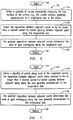
method 100 of the present invention that allows for determining the exact location of the spots at which the respective dual beams must strike the mutually opposite surfaces of the article to be laser shock peened (LSP). Subsequent to startstep 102,step 104 allows for defining a spot pattern comprising a plurality of spots on a first surface of the article, e.g., a convex surface relative to an impinging laser beam. Step 106 allows for defining a spot pattern comprising a plurality of spots on a second surface of the article, e.g., a concave surface relative to the other impinging laser beam. As suggested above, the first and second surfaces (e.g., surfaces 46 and 48 (FIG. 1)) comprise mutually opposite surfaces relative to one another. Further, each one of the spots on the second surface is arranged to correspond to a respective spot on the first surface so as to make up a plurality of matched pair of spots. Prior to returnstep 110,step 108 allows for generating dual laser beams respectively aligned to simultaneously impinge on each respective matched pair of spots. - FIG. 5 shows a flow chart illustrating further details in connection with the spot pattern that may be generated by
method 100. Subsequent to startstep 112,step 114 allows for providing a spot pattern on the first surface which pattern is made up of a plurality of overlapping spots. An example of such overlapping spot pattern is shown in FIG. 8. Step 116 allows for selectively controlling the level of overlapping between adjacent spots. As stated inblock 118 and shown in FIG. 9, each matched pair of spots is situated relative to one another so that a line extending normal to the spot on the first surface (e.g., surface 48) intersects a line extending normal relative to the spot on the second surface (e.g., surface 46). The intersection of the two normal lines occurs at a point (e.g., point o) equidistant from each spot. The above described geometry is best appreciated in FIG. 9, wherein laser beam paths Aa and Bb are assumed to be co-planar, and it is further assumed that such paths are held in a fixed position and at fixed angle while simultaneously striking a respective matched pair of spots. Points a and b respectively correspond to the spot locations on the article where the laser beams will strike the article surface. More particularly, points a and b correspond to the respective centers of the spots situated on the respective mutually opposite surfaces of the article to be LSP. Thus, as shown in FIG. 9, the distance between line segment ao and line segment bo is identical to one another. Further, line segment ao is perpendicular to the spot center onfirst surface 46 ofarticle 54. Similarly, line segment bo is perpendicular to the spot center onsecond surface 48 ofarticle 54. - FIG. 6 is a flowchart that provides further details regarding another embodiment of
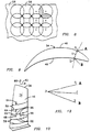
method 100 that ensures that the plurality matched pair of spots completely cover the surfaces that are required to be LSP. Subsequent to startstep 122,step 124 allows for defining a plurality of curves, such ascurves 59 in FIG. 10, respectively traversing thefirst surface 46 of the article, e.g., the convex surface, generally perpendicular to a longitudinal axis (e.g., axis 60 (FIG. 10)) of the article. Step 126 allows for selecting the separation between adjacent curves to be no longer than a desired center-to-center spacing between adjacent spots along the longitudinal axis. Prior to returnstep 130, and as indicated inblock 128, the selected separation between adjacent curves determines the level of spot overlapping along the longitudinal axis, and is represented byvertical arrows 64 in FIG. 10. - FIG. 7 shows a flowchart that allows for selecting the level of spot overlapping along the axis generally perpendicular to the longitudinal axis of the article (e.g.,
axis 62 in FIG. 10). Subsequent to startstep 132,step 134 allows for defining a plurality of points, such aspoints 66 in FIG. 10, along each of the respective curves. The separation between adjacent points is selected to be no longer than a desired center-to-center spacing between adjacent spots along the axis generally perpendicular to longitudinal axis of the article. Prior to returnstep 138, and as indicated inblock 136, the selected separation between adjacent points determines the level of spot overlapping along the axis generally perpendicular to the longitudinal axis, and such point separation is represented byhorizontal arrows 68 in FIG. 10. - FIG. 11 shows a flowchart that allows for determining the NC commands that are programmed into an article-positioning device to sequentially move the article to be LSP to precise locations so as to achieve three-dimensional alignment between the dual laser beams and each respective matched pair of spots. Subsequent to start
step 140,step 142 allows for defining an article alignment vector and an article working plane along which the article alignment vector is situated. The article alignment vector and article working plane may be defined within a suitable Computer-Aided Design (CAD) model ofarticle 54 as illustrated in FIG. 12. By way of example and not of limitation, a line segment between the two article spot points a and b is first defined. A center point of the line segment is then defined, e.g., center point c which is equidistant from points a and b. A vector CD extends from point c so that vector CD is normal relative to line segment ab. In this illustration, vector CD comprises the article alignment vector, and points a, b and article alignment vector CD define the article working plane. - Step 144 allows for defining a laser alignment vector and a laser working plane along which the laser alignment vector is situated. To define the laser alignment vector and the laser working plane, we assume a fixed dual laser beam arrangement, as shown in FIG. 13. It is further assumed that the dual laser beams A and B intersect at a known point p at a known fixed angle qps. To define the laser alignment vector, a line segment pr that bisects the angle qps is extended between the dual laser beams A and B. In this case, line segment pr comprises the laser alignment vector and the laser working plane is defined by the common plane shared by dual laser beams A and B and the laser alignment vector pr.
- Step 146 allows for executing relative rotation between the article working plane and the laser working plane to provide parallel alignment between the article working plane and the laser working plane. Step 148 allows for executing relative rotation between the part alignment vector and the laser alignment vector to provide parallel alignment between such vectors. Prior to return
step 152,step 150, which is reached through a connecting node A, allows for executing relative translation motion between the article and the dual laser beams so that one of the laser beams coincides with the center of the spot on the first surface of the article and the other of the laser beams coincides with the center of the spot on the second surface to be LSP. - It will be appreciated by those skilled in the art, that traditional NC control techniques would only require aligning the article alignment vector to a single tool axis alignment vector. However, it will be further appreciated that such traditional technique would not work in a case that requires simultaneous control of a dual laser beam. Thus, this invention has recognized the need of executing an additional alignment, namely, alignment between the article working plane and the laser working plane. The above described alignment arrangement is illustrated in FIG. 14 wherein the laser alignment vector and the article alignment vector are aligned to share a common working plane such that the center lines of dual laser beams A and B respectively, pass through points a and b, which correspond to the center of the spots on the mutually opposite surfaces to be LSP.
- Referring to FIGS. 15 and 16, the laser beam shock induced deep compressive residual stresses are produced by repetitively firing two
laser beams 2, each of which is defocused plus/minus a few mils with respect to thesurfaces 54 on both sides of the leading edge LE which may be covered with any suitableablative coating 55. The laser beam is preferably fired through a curtain of flowing water that is flowed over the coated laser shock peenedsurface 54. The paint, tape, or otherablative coating 55 is ablated generating plasma which results in shock waves on the surface of the material. Other ablative materials may be used to coat the surface as suitable alternatives to paint. These coating materials include metallic foil or adhesive plastic tape as disclosed inU.S. Pat. No. 5,674,329 and5,674,328 . These shock waves are re-directed towards the coated surface by the curtain of flowing water to generate travelling shock waves (pressure waves) in the material below the coated surface. The amplitude and quantity of these shockwave determine the depth and intensity of compressive stresses. The ablative coating is used to protect the target surface and also to generate plasma. - Illustrated in FIGS. 15 and 16 is a
system 1 which has theblade 8 mounted in a conventionally well-knownrobotic arm 27 used to continuously move and position the blade to provide laser shock peening "on the fly" in accordance with one embodiment of the present invention.Robotic arm 27 is responsive to rotational and/or linear motion imparted bysuitable servomotors 94 that are turn responsive to suitable commands from acontroller 92, e.g., an NC device, that may be programmed to implement the alignment steps discussed in the context of FIGS. 11-14. Aspot pattern generator 90 may be further programmed to implement the spot pattern defining steps discussed in the context of FIGS. 4-10. It will be appreciated that the above programming may be implemented using programming techniques that are well-known and are well-understood to one of ordinary skill in the art. - The laser shock peened surfaces 54 on both the pressure and
suction sides ablative coating 55. Then theblade 8 is continuously moved while continuously firing thestationary laser beams 2 through a curtain of flowingwater 21 on thesurfaces 54 and forming the controllably overlapping laser shock peenedcircular spots 58. The curtain ofwater 21 is illustrated as being supplied by aconventional water nozzle 23 at the end of a conventionalwater supply tube 19. The lasershock peening system 1 has aconventional generator 31 with anoscillator 33 and apre-amplifier 39A and abeam splitter 43 which feeds the pre-amplified laser beam into two beam optical transmission circuits each having a first andsecond amplifier optics 35 which include optical elements that transmit and focus thelaser beam 2 on the laser shock peened surfaces 54. Acontroller 24 may be used to modulate and control thelaser beam apparatus 1 to fire thelaser beams 2 on the laser shock peened surfaces 54 in a controlled manner. Ablated coating material is washed out by the curtain of flowing water. - The laser may be fired sequentially "on the fly" so that the laser shock peened
surface 54 is laser shock peened with more than one sequence of coating the surface and then laser shock peening the surface while continuously effecting movement between theairfoil 34 ofblade 8 and thelaser beams 2 as illustrated in FIGS. 15 and 16. In the illustrative embodiment herein, theairfoil 34 is moved while continuously firing thelaser beams 2 on thesurfaces 54 such that respective matched pairs of circular spots are simultaneously impinged by the dual laser beams. The sequence of coating and laser shock peening may be repeated several times to attain a desired strength of compressive residual stresses and depth of the laser shock peened protrusions 53. - It will be appreciated by those skilled in the art that method may be adapted so that only virgin or near virgin coating is ablated away without any appreciable effect or damage on the surface of the airfoil. This is to prevent even minor blemishes or remelt due to the laser which might otherwise cause unwanted aerodynamic effects on the blade's operation. Several sequences may be required to cover the entire pattern and re-coating of the laser shock peened surfaces 54 is done between each sequence of laser firings wherein each spot pair is hit several times. The laser firing has multiple laser firings or pulses with a period between firings that is often referred to a "rep". During the rep the part is moved so that the next pulse occurs at the location of the next laser shocked peened circular spot pair. Preferably, the part is moved continuously and timed to be at the appropriate location at the pulse or firing of the laser beam. One or more repeats of the sequence may be used to hit each laser shocked peened circular spot pair more than once. This may also allow for less laser power to be used in each firing or laser pulse.
Claims (7)
- A method for dual laser shock peening an article, the method comprising:defining a spot pattern comprising a plurality of spots on a first surface of the article to be peened;defining a spot pattern comprising a plurality of spots on a second surface of the article to be peened, the first and second surfaces comprising mutually opposite surfaces relative to one another, each one of the respective spots on the second surface being arranged to correspond to a respective spot on the first surface and comprising a plurality of matched pair of spots; and:generating dual laser beams being respectively aligned to simultaneously impinge on each respective matched pair of spots; characterised in thata three dimensional alignment of the dual laser beams relative to the article comprises:defining an article alignment vector and an article working plane along which the article alignment vector is situated;defining a laser alignment vector and a laser working plane along which the laser alignment vector is situated;executing relative rotation between the article working plane and the laser working plane to provide parallel alignment between the article alignment vector and the laser alignment vector; andexecuting relative translation motion between the article and the dual laser beams so that one of the laser beams coincides with the center point of the spot on the first surface and the other of the laser beams coincides with the center point of the spot on the second surface.
- The method of claim 1 wherein the first surface comprises a convex surface.
- The method of claim 1 or 2 wherein the spot pattern on the first surface comprises a plurality of overlapping spots.
- The method of claim 3 further comprising a step of selectively controlling the level of overlapping between adjacent spots.
- The method of any preceding claim wherein the second surface comprises a concave surface.
- An apparatus for dual laser shock peening an article, the apparatus comprising:a spot pattern generator for defining a spot pattern comprising a plurality of spots on a first surface of the article to be peened, the pattern generator further defining a spot pattern comprising a plurality of spots on a second surface of the article to be peened, the first and second surfaces comprising mutually opposite surfaces relative to one another, each one of the respective spots on the second surface being arranged to correspond to a respective spot on the first surface and comprising a plurality of matched pair of spots; anda laser unit for generating dual laser beams being respectively aligned to simultaneously impinge on each respective matched pair of spots, characterised in thata three dimensional alignment of the dual laser beams relative to the article is performed by a processor comprising:a module for defining an article alignment vector and an article working plane along which the article alignment vector is situated;a module for defining a laser alignment vector and a laser working plane along which the laser alignment vector is situated;a module for executing relative rotation between the article working plane and the laser working plane to provide parallel alignment between the article alignment vector and the laser alignment vector; anda module for executing relative translation motion between the article and the dual laser beams so that one of the laser beams coincides with the center point of the spot on the first surface and the other of the laser beams coincides with the center point of the spot on the second surface.
- The apparatus of claim 6 further comprising an overlap control module for selectively controlling the level of overlapping between adjacent spots,
Applications Claiming Priority (2)
| Application Number | Priority Date | Filing Date | Title |
|---|---|---|---|
| US494715 | 2000-01-31 | ||
| US09/494,715 US6479790B1 (en) | 2000-01-31 | 2000-01-31 | Dual laser shock peening |
Publications (3)
| Publication Number | Publication Date |
|---|---|
| EP1122321A2 EP1122321A2 (en) | 2001-08-08 |
| EP1122321A3 EP1122321A3 (en) | 2003-11-05 |
| EP1122321B1 true EP1122321B1 (en) | 2007-11-21 |
Family
ID=23965666
Family Applications (1)
| Application Number | Title | Priority Date | Filing Date |
|---|---|---|---|
| EP01300696A Expired - Lifetime EP1122321B1 (en) | 2000-01-31 | 2001-01-26 | Dual Laser shock peening |
Country Status (8)
| Country | Link |
|---|---|
| US (1) | US6479790B1 (en) |
| EP (1) | EP1122321B1 (en) |
| JP (1) | JP4656735B2 (en) |
| BR (1) | BRPI0100222B1 (en) |
| DE (1) | DE60131482T2 (en) |
| PL (1) | PL196802B1 (en) |
| SG (1) | SG91326A1 (en) |
| TR (1) | TR200003699A2 (en) |
Families Citing this family (20)
| Publication number | Priority date | Publication date | Assignee | Title |
|---|---|---|---|---|
| US6664506B2 (en) | 2001-08-01 | 2003-12-16 | Lsp Technologies, Inc. | Method using laser shock processing to provide improved residual stress profile characteristics |
| US6759626B2 (en) * | 2001-08-01 | 2004-07-06 | L&P Technologies, Inc. | System for laser shock processing objects to produce enhanced stress distribution profiles |
| US6875953B2 (en) | 2002-07-29 | 2005-04-05 | Lsp Technologies, Inc. | Method using laser shock processing to provide improved residual stress profile characteristics |
| GB2398034B (en) * | 2003-02-04 | 2005-08-10 | Rolls Royce Plc | Laser shock peening |
| US6969821B2 (en) * | 2003-06-30 | 2005-11-29 | General Electric Company | Airfoil qualification system and method |
| US7109436B2 (en) * | 2003-08-29 | 2006-09-19 | General Electric Company | Laser shock peening target |
| US7148448B2 (en) * | 2003-10-31 | 2006-12-12 | General Electric Company | Monitored laser shock peening |
| US8049137B2 (en) * | 2004-02-13 | 2011-11-01 | Boston Scientific Scimed, Inc. | Laser shock peening of medical devices |
| US8132460B1 (en) | 2004-09-27 | 2012-03-13 | Lsp Technologies, Inc. | Laser induced bond delamination |
| US7897895B2 (en) * | 2006-05-01 | 2011-03-01 | General Electric Company | System and method for controlling the power level of a laser apparatus in a laser shock peening process |
| US8330070B2 (en) * | 2006-05-11 | 2012-12-11 | Kabushiki Kaisha Toshiba | Laser shock hardening method and apparatus |
| FR2921448A1 (en) * | 2007-09-24 | 2009-03-27 | Snecma Sa | METHOD FOR FORMING RELIEF RELIEFS OF LIMITED LAYER |
| US7509876B1 (en) * | 2007-10-17 | 2009-03-31 | Lsp Technologies, Inc. | Laser bond inspection using annular laser beam |
| DE102007056502B4 (en) | 2007-11-22 | 2010-07-29 | Eads Deutschland Gmbh | Method and device for building up residual stresses in a metallic workpiece |
| US8359924B1 (en) | 2010-07-01 | 2013-01-29 | The Boeing Company | Bond interface testing |
| EP2903776B8 (en) | 2012-10-01 | 2021-04-07 | Raytheon Technologies Corporation | Methods for testing laser shock peening |
| US9764422B2 (en) | 2013-03-15 | 2017-09-19 | United Technologies Corporation | Sequencing of multi-pass laser shock peening applications |
| US10434603B2 (en) * | 2014-06-21 | 2019-10-08 | Apple Inc. | Forming a textured pattern using a laser |
| CN104862468B (en) * | 2015-06-11 | 2017-03-22 | 温州大学 | Method for prolonging service life of turbine blade based on laser double-faced impact technique |
| CN106112268B (en) * | 2016-07-22 | 2017-09-19 | 广东工业大学 | A kind of band muscle wallboard laser shot forming system and method |
Family Cites Families (29)
| Publication number | Priority date | Publication date | Assignee | Title |
|---|---|---|---|---|
| JPS6160290A (en) * | 1984-08-31 | 1986-03-27 | Toyota Motor Corp | Work processing method using laser |
| US4638143A (en) * | 1985-01-23 | 1987-01-20 | Gmf Robotics Corporation | Robot-laser system |
| US5072091A (en) * | 1989-04-03 | 1991-12-10 | The Local Government Of Osaka Prefecture | Method and apparatus for metal surface process by laser beam |
| US4987044A (en) * | 1989-05-31 | 1991-01-22 | E. I. Du Pont De Nemours And Company | Method and apparatus for maintaining desired exposure levels |
| US4937421A (en) * | 1989-07-03 | 1990-06-26 | General Electric Company | Laser peening system and method |
| JPH03281083A (en) * | 1990-03-29 | 1991-12-11 | Fanuc Ltd | Attitude control system for cnc laser beam machine |
| US5239159A (en) * | 1990-05-31 | 1993-08-24 | Fanuc Ltd. | Nozzle movement system for laser machining equipment |
| US5268554A (en) | 1992-06-29 | 1993-12-07 | General Electric Co. | Apparatus and system for positioning a laser beam |
| US5340962A (en) * | 1992-08-14 | 1994-08-23 | Lumonics Corporation | Automatic control of laser beam tool positioning |
| US5492447A (en) * | 1994-10-06 | 1996-02-20 | General Electric Company | Laser shock peened rotor components for turbomachinery |
| US6215097B1 (en) * | 1994-12-22 | 2001-04-10 | General Electric Company | On the fly laser shock peening |
| US5591009A (en) * | 1995-01-17 | 1997-01-07 | General Electric Company | Laser shock peened gas turbine engine fan blade edges |
| US5569018A (en) * | 1995-03-06 | 1996-10-29 | General Electric Company | Technique to prevent or divert cracks |
| US5531570A (en) * | 1995-03-06 | 1996-07-02 | General Electric Company | Distortion control for laser shock peened gas turbine engine compressor blade edges |
| US5674329A (en) * | 1996-04-26 | 1997-10-07 | General Electric Company | Adhesive tape covered laser shock peening |
| US5822211A (en) * | 1996-11-13 | 1998-10-13 | International Business Machines Corporation | Laser texturing apparatus with dual laser paths having an independently adjusted parameter |
| US5911890A (en) * | 1997-02-25 | 1999-06-15 | Lsp Technologies, Inc. | Oblique angle laser shock processing |
| JP3213882B2 (en) * | 1997-03-21 | 2001-10-02 | 住友重機械工業株式会社 | Laser processing apparatus and processing method |
| US5904869A (en) * | 1997-05-01 | 1999-05-18 | Snk Corporation | Automatic laser beam machining apparatus and performing automatic laser beam machining method |
| KR100446052B1 (en) * | 1997-05-15 | 2004-10-14 | 스미도모쥬기가이고교 가부시키가이샤 | Laser beam machining apparatus using a plurality of galvanoscanners |
| US6068728A (en) * | 1997-08-28 | 2000-05-30 | Seagate Technology, Inc. | Laser texturing with reverse lens focusing system |
| US5911891A (en) * | 1997-09-11 | 1999-06-15 | Lsp Technologies, Inc. | Laser shock peening with tailored multiple laser beams |
| US6144012A (en) * | 1997-11-05 | 2000-11-07 | Lsp Technologies, Inc. | Efficient laser peening |
| US5932120A (en) * | 1997-12-18 | 1999-08-03 | General Electric Company | Laser shock peening using low energy laser |
| US6005219A (en) * | 1997-12-18 | 1999-12-21 | General Electric Company | Ripstop laser shock peening |
| US6002706A (en) * | 1997-12-30 | 1999-12-14 | General Electric Company | Method and apparatus for controlling the size of a laser beam |
| US6292584B1 (en) * | 1998-04-08 | 2001-09-18 | Lsp Technologies, Inc. | Image processing for laser peening |
| US6075593A (en) * | 1999-08-03 | 2000-06-13 | General Electric Company | Method for monitoring and controlling laser shock peening using temporal light spectrum analysis |
| US6296448B1 (en) * | 1999-09-30 | 2001-10-02 | General Electric Company | Simultaneous offset dual sided laser shock peening |
-
2000
- 2000-01-31 US US09/494,715 patent/US6479790B1/en not_active Expired - Fee Related
- 2000-12-13 TR TR2000/03699A patent/TR200003699A2/en unknown
- 2000-12-21 PL PL344732A patent/PL196802B1/en not_active IP Right Cessation
-
2001
- 2001-01-18 SG SG200100242A patent/SG91326A1/en unknown
- 2001-01-26 DE DE60131482T patent/DE60131482T2/en not_active Expired - Lifetime
- 2001-01-26 EP EP01300696A patent/EP1122321B1/en not_active Expired - Lifetime
- 2001-01-30 JP JP2001020886A patent/JP4656735B2/en not_active Expired - Fee Related
- 2001-01-31 BR BRPI0100222A patent/BRPI0100222B1/en not_active IP Right Cessation
Also Published As
| Publication number | Publication date |
|---|---|
| JP2001293583A (en) | 2001-10-23 |
| JP4656735B2 (en) | 2011-03-23 |
| BRPI0100222B1 (en) | 2017-04-25 |
| EP1122321A3 (en) | 2003-11-05 |
| EP1122321A2 (en) | 2001-08-08 |
| BR0100222A (en) | 2001-09-18 |
| PL196802B1 (en) | 2008-02-29 |
| TR200003699A2 (en) | 2001-09-21 |
| US6479790B1 (en) | 2002-11-12 |
| DE60131482D1 (en) | 2008-01-03 |
| DE60131482T2 (en) | 2008-09-18 |
| SG91326A1 (en) | 2002-09-17 |
| PL344732A1 (en) | 2001-08-13 |
Similar Documents
| Publication | Publication Date | Title |
|---|---|---|
| EP1122321B1 (en) | Dual Laser shock peening | |
| EP1227164B1 (en) | Laser shock peening integrally bladed rotor blade edges | |
| US6005219A (en) | Ripstop laser shock peening | |
| US5932120A (en) | Laser shock peening using low energy laser | |
| US5674328A (en) | Dry tape covered laser shock peening | |
| US5744781A (en) | Method and apparatus for laser shock peening | |
| US5674329A (en) | Adhesive tape covered laser shock peening | |
| US6215097B1 (en) | On the fly laser shock peening | |
| US6333488B1 (en) | Method for setting up and controlling confinement media flow in laser shock peening | |
| EP1288317A1 (en) | Simultaneous offset dual sided laser shock peening with oblique angle laser beams | |
| US6159619A (en) | Ripstop laser shock peening | |
| US7736450B2 (en) | Varying fluence as a function of thickness during laser shock peening | |
| EP1088903B1 (en) | Simultaneous offset dual sided laser shock peening | |
| US6551064B1 (en) | Laser shock peened gas turbine engine intermetallic parts | |
| EP1288318B1 (en) | Simultaneous offset dual sided laser shock peening using low energy laser beams | |
| EP1380657B1 (en) | Single sided laser shock peening |
Legal Events
| Date | Code | Title | Description |
|---|---|---|---|
| PUAI | Public reference made under article 153(3) epc to a published international application that has entered the european phase |
Free format text: ORIGINAL CODE: 0009012 |
|
| AK | Designated contracting states |
Kind code of ref document: A2 Designated state(s): AT BE CH CY DE DK ES FI FR GB GR IE IT LI LU MC NL PT SE TR |
|
| AX | Request for extension of the european patent |
Free format text: AL;LT;LV;MK;RO;SI |
|
| PUAL | Search report despatched |
Free format text: ORIGINAL CODE: 0009013 |
|
| AK | Designated contracting states |
Kind code of ref document: A3 Designated state(s): AT BE CH CY DE DK ES FI FR GB GR IE IT LI LU MC NL PT SE TR |
|
| AX | Request for extension of the european patent |
Extension state: AL LT LV MK RO SI |
|
| RIC1 | Information provided on ipc code assigned before grant |
Ipc: 7B 23K 26/02 B Ipc: 7C 21D 10/00 A |
|
| 17P | Request for examination filed |
Effective date: 20040506 |
|
| AKX | Designation fees paid |
Designated state(s): DE FR GB |
|
| 17Q | First examination report despatched |
Effective date: 20041111 |
|
| GRAP | Despatch of communication of intention to grant a patent |
Free format text: ORIGINAL CODE: EPIDOSNIGR1 |
|
| GRAS | Grant fee paid |
Free format text: ORIGINAL CODE: EPIDOSNIGR3 |
|
| GRAA | (expected) grant |
Free format text: ORIGINAL CODE: 0009210 |
|
| AK | Designated contracting states |
Kind code of ref document: B1 Designated state(s): DE FR GB |
|
| REG | Reference to a national code |
Ref country code: GB Ref legal event code: FG4D |
|
| REF | Corresponds to: |
Ref document number: 60131482 Country of ref document: DE Date of ref document: 20080103 Kind code of ref document: P |
|
| ET | Fr: translation filed | ||
| PLBE | No opposition filed within time limit |
Free format text: ORIGINAL CODE: 0009261 |
|
| STAA | Information on the status of an ep patent application or granted ep patent |
Free format text: STATUS: NO OPPOSITION FILED WITHIN TIME LIMIT |
|
| 26N | No opposition filed |
Effective date: 20080822 |
|
| PGFP | Annual fee paid to national office [announced via postgrant information from national office to epo] |
Ref country code: GB Payment date: 20130125 Year of fee payment: 13 Ref country code: FR Payment date: 20130211 Year of fee payment: 13 Ref country code: DE Payment date: 20130129 Year of fee payment: 13 |
|
| REG | Reference to a national code |
Ref country code: DE Ref legal event code: R119 Ref document number: 60131482 Country of ref document: DE |
|
| GBPC | Gb: european patent ceased through non-payment of renewal fee |
Effective date: 20140126 |
|
| PG25 | Lapsed in a contracting state [announced via postgrant information from national office to epo] |
Ref country code: DE Free format text: LAPSE BECAUSE OF NON-PAYMENT OF DUE FEES Effective date: 20140801 |
|
| REG | Reference to a national code |
Ref country code: FR Ref legal event code: ST Effective date: 20140930 |
|
| REG | Reference to a national code |
Ref country code: DE Ref legal event code: R119 Ref document number: 60131482 Country of ref document: DE Effective date: 20140801 |
|
| PG25 | Lapsed in a contracting state [announced via postgrant information from national office to epo] |
Ref country code: GB Free format text: LAPSE BECAUSE OF NON-PAYMENT OF DUE FEES Effective date: 20140126 Ref country code: FR Free format text: LAPSE BECAUSE OF NON-PAYMENT OF DUE FEES Effective date: 20140131 |